- Type
- Operating instructions

Manual No.
DDCV-OM4-1
2”-12” Grooved End
Dual Disc
Check Valve
Operation, Maintenance and
Installation Manual
INTRODUCTION ................................................. 1
RECEIVING AND STORAGE .............................. 1
DESCRIPTION OF OPERATION ........................ 1
INSTALLATION ................................................... 2
VALVE CONSTRUCTION ................................... 3
MAINTENANCE .................................................. 4
TROUBLESHOOTING ........................................ 4
DISASSEMBLY ................................................... 4
REASSEMBLY .................................................... 4
PARTS AND SERVICE ....................................... 5
WARRANTY ........................................................ 5
VAL-MATIC
®
VALVE AND MANUFACTURING CORP.
905 Riverside Dr. ● Elmhurst, IL 60126
Phone (630) 941-7600 ● Fax (630) 941-8042
www.valmatic.com

1
CAUTION
This valve is not intended for fluids
containing suspended solids or hazardous
fluids.
2”-12” GROOVED END DUAL DISC CHECK VALVE
OPERATION, MAINTENANCE AND INSTALLATION
INTRODUCTION
This manual will provide you with the information to
properly install and maintain the valve to ensure a
long service life. The Dual Disc Check Valve is
ruggedly constructed with bronze or stainless steel
trim to give years of trouble free operation. The
valve should be installed in horizontal or vertical flow
up pipes carrying clean water. The valves can be
equipped with special springs for operation in blower
air service (Series 8900).
The Dual Disc Check Valve is designed to open
fully to provide flow in the forward direction and
close rapidly upon flow reversal. The valves are
used to prevent reverse flow through pumps or in
piping systems. The size, cold working pressure,
and model number are stamped on the nameplate
for reference.
This valve is not intended for fluids containing
suspended solids such as wastewater. For
wastewater and other high turbidity applications, use
Val-Matic Series 500 Swing-Flex® Check Valves.
RECEIVING AND STORAGE
Inspect valves upon receipt for damage in shipment.
Unload all valves carefully to the ground without
dropping. When lifting, the valve should be secured
by the body and never lifted by the bronze or
stainless steel trim. Threaded holes are provided on
the top of 10” and larger valves for the insertion of
an eye bolt.
The valves should remain crated, clean and dry until
installed to prevent weather related damage. For
long term storage greater than six months, the
rubber surfaces of the seat (when provided) should
be coated with a thin film of FDA approved grease.
Do not expose rubber seat to sunlight or ozone for
any extended period.
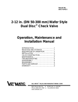
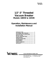
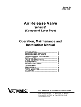
FIGURE 1. DUAL DISC CHECK VALVE
DESCRIPTION OF OPERATION
The Dual Disc Check Valve is designed to prevent
reverse flow automatically. On pump start-up, the
flow of water enters the valve from the seat end (left
side in Figure 1) and forces the two discs open until
they strike the disc stop pin. On pump shut-down,
the torsion spring closes the disc before a flow
reversal takes place.
The valve body is supplied with grooved ends for
installation with AWWA C606 couplings.
The only moving parts in the valve are the discs and
spring. The discs and spring are guided in the body
with a hinge pin and a full open disc stop pin. The
pins are restrained in the body by stabilization
spheres to prevent vibration. The valve also has a
resilient seat for drop tight shut off.
STOP PIN
HINGE PIN
BODY
DISC

2
INSTALLATION
The installation of the valve is important for its
proper operation. The flow arrow on the valve body
or nameplate must point in the direction of flow when
the system is in operation. The valve can be
installed in horizontal or vertical lines with the flow
up. Valves for air service (Series 8900) require
special springs to allow full valve opening.
The valve should be installed between steel OD
grooved pipe ends. The gasket and coupling should
be supplied per AWWA C606 for IPS diameter pipe.
Three diameters of straight pipe upstream of the
valve are recommended to prevent turbulent flow
streams through the valve, which can cause
vibration and wear.
When mating the check valve with butterfly isolation
valves, the isolation valve must be installed at least
one diameter downstream of the check valve. The
check valve discs extend beyond the downstream
flange face and may interfere with the operation of
adjacent valves. A short run of pipe or spacer is
needed between the check valve and the isolation
valve.
INSTALLATION: Lower valve between mating
flange using slings or chains around the valve body.
10” and larger valves have a tapped hole for
insertion of a lifting eye if needed. Lubricate the
coupling gasket and install coupling around the
valve end. Lightly turn the coupling bolts or nuts
until gaps are eliminated. The tightening of the bolts
should then be done in graduated steps keeping the
gaps uniform.
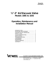
TABLE 1. GROOVED END DIMENSIONS

3
WARNING
Removal of pipe couplings without draining
the pipeline may cause injury or damage to
the valve.
VALVE CONSTRUCTION
The standard check valve body (1) is constructed of
cast ductile iron. See the specific Materials List
submitted for the order if other than standard iron
construction. The internal metal components are
bronze or stainless steel. The discs (2) and torsion
spring (3) are the only moving parts and require no
maintenance or lubrication. The general details of
construction are illustrated in Figure 2.
The body (1) is either compact wafer style to fit
between grooved pipe ends. The resilient seat is
bonded to the body and is not adjustable or
replaceable in the field.
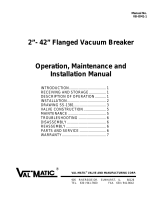
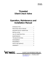
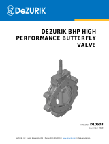
FIGURE 2. DUAL DISC CHECK VALVE
Table 2. Check Valve Parts List
Item Description Material
1 Body Ductile Iron
2 Disc Bronze
3 Spring* Stainless Steel
4 Hinge Pin Stainless Steel
5 Stop Pin Stainless Steel
6 Washer Stainless Steel
7 Hinge Pin Ret.* Steel
8 Stop Pin Ret.* Steel
9 Stab. Sphere* Buna-N
10 Spacer* Stainless Steel
* Recommended Spare Part
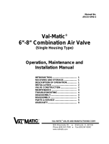
FIGURE 3. DUAL DISC CHECK VALVE

4
WARNING
The line must be drained before removing
the valve or pressure may be released
causing injury.
MAINTENANCE
Dual Disc Check Valves require no scheduled
lubrication of maintenance.
INSPECTION: Periodic inspection for leakage can
be performed by listening for leakage noise from the
valve while the pump is shut down. If leakage is
heard, drain the pipeline, remove the valve, and
inspect the seating surfaces for wear or damage. If
the resilient seat is damaged, replace the valve or
return the valve to the factory for refurbishing.
TROUBLESHOOTING
Several problems and solutions are presented below
to assist you in trouble shooting the valve assembly
in an efficient manner.
Valve Chatters or Vibrates: Verify that velocity is
at least 4 feet per second (consult the factory for
air service). A partially open valve will wear
prematurely. Verify that there are three diameters
of straight pipe upstream.
Valve Leakage: Check coupling gaskets and
flange torques. Drain line, remove couplings, and
inspect gasket surfaces.
Valve Does Not Pass Flow: Check flow arrow
direction on valve body. Verify that downstream
isolation valve is open and there is no line
blockage downstream.
Valve Slams: Remove valve and inspect spring.
Heavier springs can be furnished for severe high-
head applications. Consult factory if the valve is
installed in a vertical pipe with the flow downward.
DISASSEMBLY
The valve should be removed from the pipeline for
disassembly. All work on the valve should be
performed by a skilled mechanic with proper tools.
Refer to Figure 2.
1. Remove the valve from the pipeline. 10” and
larger valves have threaded holes for insertion of
an eye bolt. Lay valve on flat surface or bench
with the flow arrow facing upwards.
2. Remove the threaded pin retainers (8) and the
rubber spheres (9).
3. Drive out the pins (4 and 5) with a round bar or
punch while pressing down on the spring (3) to
prevent it from unwinding.
4. Lift discs (2) from body. Inspect pins and seating
surfaces for wear. The shaft diameter is normally
about 1/16” smaller in diameter than the hole in
the disc lugs. Some minor dents and discoloration
are normal. Wear areas in the resilient seat will
cause leakage and require valve replacement or
refurbishing at the factory.
5. Remove spring (3) and check for wear or cracks.
6. Remove spacers (10) and washers (9) and
inspect for wear.
REASSEMBLY
All parts must be clean and the gasket surfaces
should be cleaned with a stiff wire brush in the
direction of the serrations or machine marks. Worn
parts, gaskets, and seals should be replaced during
reassembly.
1. Lay body on flat surface with arrow facing
upwards. Carefully place the two discs with the
machined sealing surfaces down on the body
sealing surface. Align the disc lugs with the pin
holes in the body.
2. Insert the disc hinge pin into the hole on one side
of the body, but not through the disc lugs. Install a
spacer (10) between the inside diameter of the
body and the disc lug. Push the disc hinge pin
further to engage the first disc lug and washer.
3. Install the second spacer (10) between the first
and second disc lugs and push the pin further to
engage the second disc lug.
4. While holding the torsion spring (3) with one of the
ends facing you, wind the rear tab 180 degrees in
a clockwise direction and then press the spring
between the two sets of disc lugs. Engage the pin
further to retain the spring and the third disc lug.
The legs of the spring should apply a downward
force on the discs.

5
LIMITED WARRANTY
All products are warranted to be free of defects in material and workmanship for a period of one year from the date of shipment,
subject to the limitations below.
If the purchaser believes a product is defective, the purchaser shall: (a) Notify the manufacturer, state the alleged defect and
request permission to return the product; (b) if permission is given, return the product with transportation prepaid. If the product
is accepted for return and found to be defective, the manufacturer will, at his discretion, either repair or replace the product,
f.o.b. factory, within 60 days of receipt, or refund the purchase price. Other than to repair, replace or refund as described
above, purchaser agrees that manufacturer shall not be liable for any loss, costs, expenses or damages of any kind arising out
of the product, its use, installation or replacement, labeling, instructions, information or technical data of any kind, description of
product use, sample or model, warnings or lack of any of the foregoing. NO OTHER WARRANTIES, WRITTEN OR ORAL,
EXPRESS OR IMPLIED, INCLUDING THE WARRANTIES OF FITNESS FOR A PARTICULAR PURPOSE AND
MERCHANTABILITY, ARE MADE OR AUTHORIZED. NO AFFIRMATION OF FACT, PROMISE, DESCRIPTION OF
PRODUCT OF USE OR SAMPLE OR MODEL SHALL CREATE ANY WARRANTY FROM MANUFACTURER, UNLESS
SIGNED BY THE PRESIDENT OF THE MANUFACTURER. These products are not manufactured, sold or intended for
personal, family or household purposes.
REASSEMBLY (Continued)
5. While pushing the pin further, install the other
washer (9) and spacer (10) The pin should now
be centered in the body and the disc should rotate
without binding.
6. Insert the disc stop pin (5) into the holes in the
body.
7. Insert a sphere (9) into each of the four pin holes.
8. Place a small amount of pipe thread sealant such
as Loctite 680 on the retainer plugs (7 and 8) and
tighten into place with an Allen wrench.
9. Stand the valve on its edge with the pins vertical
and verify smooth operation of the valve before
installation into the pipeline. Apply a light coat of
silicone grease on the rubber seat for air service
valves (Series 8900).
PARTS AND SERVICE
Parts and service are available from your local
representative or the factory. Make note of the
Valve Size and Model Number located on the valve
nameplate and contact:
Val-Matic Valve and Manufacturing Corp.
905 Riverside Drive
Elmhurst, IL 60126
Phone: (630) 941-7600
Fax: (630) 941-8042
www.valmatic.com
A sales representative will quote prices for parts or
arrange for service as needed.
VAL-MATIC
®
VALVE AND MANUFACTURING CORP.
905 Riverside Dr. ● Elmhurst, IL 60126
Phone (630) 941-7600 ● Fax (630) 941-8042
www.valmatic.com
-
 1
1
-
2
-
3
-
4
-
5
-
6
- Type
- Operating instructions
Ask a question and I''ll find the answer in the document
Finding information in a document is now easier with AI
Related papers
-
 Val-Matic Dual Disc Check Valve Operating instructions
-
 Val-Matic Dual Disc Check Valve Operating instructions
-
 Val-Matic Air/Vacuum Valve Operating instructions
-
 Val-Matic Vacuum Breaker Air Valve Operating instructions
-
 Val-Matic Surge Suppression Air Valve Operating instructions
-
 Val-Matic Vacuum Breaker Air Valve Operating instructions
-
 Val-Matic Silent Check Valve Operating instructions
-
 Val-Matic Combination Air Valve Operating instructions
-
 Val-Matic Surge Suppression Air Valve Operating instructions
-
 Val-Matic Air Release Valve Operating instructions


Other documents
-
Watts FPP User guide
-
Watts 007DCDA User guide
-
Bray /Rite - Single Door Wafer Type Swing Check Valve Owner's manual
-
American Flow Control C504A010703PRPR Installation guide
-
Keystone Dual Plate Check Valve, Model MB IOM Owner's manual
-
-
Febco 850 Large Maintenance Manual
-
Zurn 212-375ASTOSY Installation guide
-
 DeZurik VALVE BHP 2-20" - TT/TI/RT/TI SEATS Operating instructions
-
Emerson C471 User manual
