Page is loading ...


DeZURIK
Instruction and Operating Manual Page 2 © 2022 DeZURIK, Inc.
Instructions
These instructions are for use by personnel who are responsible for the installation, operation and
maintenance of DeZURIK valves, actuators or accessories.
Safety Messages
All safety messages in the instructions are identified by a general warning sign and the signal word CAUTION,
WARNING or DANGER. These messages indicate procedures to avoid injury or death.
Safety label(s) on the product indicate hazards that can cause injury or death. If a safety label becomes difficult
to see or read, or if a label has been removed, please contact DeZURIK for replacement label(s).
Personnel involved in the installation or maintenance of valves should be constantly alert to potential
emission of pipeline material and take appropriate safety precautions. Always wear suitable protection
when dealing with hazardous pipeline materials. Handle valves which have been removed from service
with suitable protection for any potential pipeline material in the valve.
Inspection
Your DeZURIK product has been packaged to provide protection during shipment; however, items can be
damaged in transport. Carefully inspect the unit for damage upon arrival and file a claim with the carrier if
damage is apparent.
Parts
Replaceable wear parts are listed on the assembly drawing. These parts can be stocked to minimize
downtime. Order parts from your local DeZURIK sales representative or directly from DeZURIK. When ordering
parts please provide the following information:
If the valve has a data plate: please include the 7-digit part number with either 4-digit revision number
(example: 9999999R000) or 8-digit serial number (example: S1900001) whichever is applicable. The
data plate will be attached to the valve assembly. Also, include the part name, the assembly drawing
number, the balloon number and the quantity stated on the assembly drawing.
If there isn't any data plate visible on the valve: please include valve model number, part name, and
item number from the assembly drawing. You may contact your local DeZURIK Representative to help
you identify your valve.
DeZURIK Service
DeZURIK service personnel are available to maintain and repair all DeZURIK products. DeZURIK also offers
customized training programs and consultation services. For more information, contact your local DeZURIK
sales representative or visit our website at DeZURIK.com.

DeZURIK
BHP High Performance Butterfly Valves
November 2020 Page 3 D10503
Table of Contents
Description - - - - - - - - - - - - - - - - - - - - - - - - - - - - - - - - - - - - - - - - - - - - - - - - - - - - - - - - - - 4
Handling - - - - - - - - - - - - - - - - - - - - - - - - - - - - - - - - - - - - - - - - - - - - - - - - - - - - - - - - - - - - 4
Installing Valve - - - - - - - - - - - - - - - - - - - - - - - - - - - - - - - - - - - - - - - - - - - - - - - - - -- - - - - - 4
Requirements - - - - - - - - - - - - - - - - - - - - - - - - - - - - - - - - - - - - - - - - - - - - - - - - -- - - - - - 4
Installing Valve - - - - - - - - - - - - - - - - - - - - - - - - - - - - - - - - - - - - - - - - - - - - - - - -- - - - - - 5
Operation - - - - - - - - - - - - - - - - - - - - - - - - - - - - - - - - - - - - - - - - - - - - - - - - - - - - - -- - - - - - 5
Required Tools - - - - - - - - - - - - - - - - - - - - - - - - - - - - - - - - - - - - - - - - - - - - - - - - - -- - - - - - 5
Lubrication - - - - - - - - - - - - - - - - - - - - - - - - - - - - - - - - - - - - - - - - - - - - - - - - - - - - -- - - - - - 5
Adjusting Packing - - - - - - - - - - - - - - - - - - - - - - - - - - - - - - - - - - - - - - - - - - - - - - - -- - - - - - 5
Drawings - - - - - - - - - - - - - - - - - - - - - - - - - - - - - - - - - - - - - - - - - - - - - - - - - - - - - -- - - - - - 6
Replacing Packing - - - - - - - - - - - - - - - - - - - - - - - - - - - - - - - - - - - - - - - - - - - - - - -- - - - - - 7
PTFE V-Flex Dual-Seal Live-Loaded Packing Option (TCDL) - - - - - - - - - - - - - - - - - - - - - 8
PTFE V-Flex Packing Option (TC) - - - - - - - - - - - - - - - - - - - - - - - - - - - - - - - - - - -- - - - - - 9
PTFE Dual-Seal with Mechanical Spring Packing Option (TMD) - - - - - - - - - - - - - -- - - - - - 10
PTFE V-Flex Live-Loaded Packing Option (TCL) - - - - - - - - - - - - - - - - - - - - - - - -- - - - - - 11
Carbon Graphite Packing Option (G1) - - - - - - - - - - - - - - - - - - - - - - - - - - - - - - - -- - - - - - 12
Graphoil Packing Option (G2) - - - - - - - - - - - - - - - - - - - - - - - - - - - - - - - - - - - - - -- - - - - - 12
Graphoil Live-Loaded Packing Option (G2L) - - - - - - - - - - - - - - - - - - - - - - - - - - - - - - - - - 13
Graphoil Dual-Seal Packing Option (G2D) - - - - - - - - - - - - - - - - - - - - - - - - - - - - -- - - - - - 14
Graphoil Dual-Seal Live-Loaded Packing Option (G2LD) - - - - - - - - - - - - - - - - - - -- - - - - - 15
Torque Specification - - - - - - - - - - - - - - - - - - - - - - - - - - - - - - - - - - - - - - - - - - - - - -- - - - - - 17
Seat Replacement - - - - - - - - - - - - - - - - - - - - - - - - - - - - - - - - - - - - - - - - - - - - - -- - - - - - - 20
Removing Valve From Pipeline - - - - - - - - - - - - - - - - - - - - - - - - - - - - - - - - - - - - -- - - - - - 20
Replacing the Seat - - - - - - - - - - - - - - - - - - - - - - - - - - - - - - - - - - - - - - - - - - - - - -- - - - - - 20
Resilient Seat Options (TT, TI, RT and RI) - - - - - - - - - - - - - - - - - - - - - - - - - - - - -- - - - - - 21
Metal Seat Option (S2) - - - - - - - - - - - - - - - - - - - - - - - - - - - - - - - - - - - - - - - - - - -- - - - - - 22
Fyre-Block™ Seat Options (RTS2, TTS2, TIS2, and RIS2) - - - - - - - - - - - - - - - - -- - - - - - 23
Valve Disassembly - - - - - - - - - - - - - - - - - - - - - - - - - - - - - - - - - - - - - - - - - - - - - - -- - - - - - 24
Bearing Replacement - - - - - - - - - - - - - - - - - - - - - - - - - - - - - - - - - - - - - - - - - - - - - - - - - - - 25
Bearing Removal- - - - - - -- - - - - - - - - - - - - - - - - - - - - - - - - - - - - - - - - - - - - - - - -- - - - - - 25
Bearing Replacement- - - - - - - - - - - - - - - - - - - - - - - - - - - - - - - - - - - - - - - - - - - -- - - - - - 25
Valve Reassembly - - - - - - - - - - - - - - - - - - - - - - - - - - - - - - - - - - - - - - - - - - - - - - -- - - - - - 26
Pressure-Temperature Curves - - - - - - - - - - - - - - - - - - - - - - - - - - - - - - - - - - - - - - - - - - - - 29
Troubleshooting - - - - - - - - - - - - - - - - - - - - - - - - - - - - - - - - - - - - - - - - - - - - - - - - -- - - - - - 30

DeZURIK
BHP High Performance Butterfly Valves
D10503 Page 4 November 2020
Description
The High Performance Butterfly Valve is designed for on-off and throttling applications in the chemical,
power, paper, air conditioning, petroleum and refining industries.
A choice of body styles, ratings, seat and packing options, materials, actuators and accessories are
available in valve sizes from 2–20" (50– 500mm). Pressure and temperature ratings are shown on the
valve data plate.
Handling
Lifting the valve improperly may damage it. Do not fasten lifting devices to the actuator, disc or through
the seat opening in the body. Lift the valve with slings, chains or cables fastened around the valve
body, or fastened to bolts or rods through bolt holes in the flanges.
Installing Valve
Recommendations
Refer to the valve installation drawing for dimensional information.
• Installing the valve in the wrong location may cause excessive dynamic torque and damage the
valve. When pipeline fluid velocities exceed 20 fps (6.0 m/s) for 12” (300mm) and smaller valves
or 12 fps (3.6 m/s) for 14” (350mm) and larger valves, it is recommended to install the valve at
least 8 diameters from the nearest upstream elbow or pump. For best performance results,
install valve shaft parallel with elbow or pump cross section (see image below). For more
specific installation recommendations, contact your local representative or DeZURIK for
assistance.
• Valves with undrilled seat retainers are not suitable for dead-end service without a downstream
flange.
• If possible, install the valve with the shaft horizontal to provide a self-cleaning action on the seat.
Note: Install the valve so that the side opposite the seat will be on the higher pressure side
when the valve is closed. The seat side of the valve is marked “SEAT”. Pipeline flow may be in
either direction through the valve.
• Valves with the metal seat option must be installed with higher pressure on the
seat side when the valve is closed.
Use self-centering flat ring flange gaskets.
• Class 150 and Class 300 valves use mating flanges that comply with the same class of
ASME/ANSI B16.5.

DeZURIK
BHP High Performance Butterfly Valves
November 2020 Page 5 D10503
Installing Valve
Lifting the valve incorrectly can damage it. Do not fasten lifting devices to the actuator or
disc, or through the seat opening in the body. Lift the valve with slings fastened around
the valve body or attach them to bolts or rods run through holes for the pipeline flanges.
1. If the valve does not have an actuator, mount the actuator on the valve. Refer as necessary to
the actuator instructions and drawings.
2. Remove all foreign material such as weld spatter, oil, grease and dirt from the valve, flanges
and pipeline.
3. Open the valve and clean the seat and the sealing edge of the disc.
Note: Install the valve so that the side opposite the seat will be on the higher pressure side
when the valve is closed. The seat side of the valve is marked “SEAT”. Pipeline flow may be in
either direction through the valve.
• Valves with the metal seat option must be installed with higher pressure on the
seat side when the valve is closed.
4. Place the valve in the pipeline with the valve closed—handle the valve carefully so that the
flange gasket sealing surfaces do not get damaged.
5. Ensure that the valve, the pipeline and the mating connections are aligned and centered before
tightening the pipeline bolts.
6. Tighten the bolts evenly, in a crisscross pattern.
Operation
Clockwise rotation of the valve shaft closes the disc into the seat. A line on the top of the valve shaft
indicates the position of the disc when the disc is not visible.
The valve is fully closed when the flat side of the disc is parallel with the flange sealing surface on the
body. The valve is fully open when the disc is 90° counterclockwise from the closed position.
Note: The closed disc should not touch the stop lug in the body.
The actuator is connected to the valve shaft and positions the disc at the open, closed or intermediate
positions. The position stops in the actuator are set to match the open and closed positions of the valve.
Note: Refer to the actuator instructions for stop adjustment information.
Required Tools
This valve is assembled using only SAE fasteners. To service this unit, you should have a full set of
combination wrenches, Allen wrenches, a flat tipped screwdriver, a pin punch and a dead blow hammer.
Lubrication
The valve is lubricated at the factory and does not require lubrication except when it is being
reassembled. Refer to the actuator instructions for actuator lubrication requirements.
Adjusting Packing
The shaft seal consists of packing that is contained and compressed by the packing gland (A12).
1. If the packing leaks, tighten the two adjustment nuts (A15) on top of the packing gland (A12).
Note: Tighten the nuts evenly and gently—just enough to stop the leak. Over tightening will
cause excessive torque and decrease packing life.
2. If the leak cannot be stopped by tightening the packing, replace the packing. See "Replacing
Packing" section.

DeZURIK
BHP High Performance Butterfly Valves
D10503 Page 6 November 2020
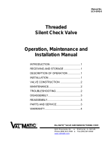
Drawings
Figure 1 – Component Identification

DeZURIK
BHP High Performance Butterfly Valves
November 2020 Page 7 D10503
Replacing Packing
Several packing options are available. See Figure 1 for parts identification.
Pipeline pressure can cause personal injury or equipment damage. Relieve the
pressure in the pipeline before removing the packing gland.
1. Discontinue flow and relieve pipeline pressure.
Accidental operation of powered actuator can cause personal injury or equipment
damage. Disconnect and lock out power to actuator before servicing.
2. If the actuator is powered, disconnect and lock out the power to the actuator.
3. Remove the actuator as described in the actuator instructions and remove the actuator bracket from
the valve.
4. Remove the two gland nuts (A15) and remove the gland (A12).
Note: Live-loaded packing options include a flat washer (A37) and several spring washers (A36)
under each gland nut. When required, the gland consists of two pieces: gland (A12) and gland plate
(A39).
5. Remove the retaining ring (A46) from the shaft (A4).
6. Remove the packing washer (A10) and all of the packing (A11).
7. If the valve has the dual packing option, remove the secondary packing chamber (A17), the gasket
(A16) and the secondary packing (A26).
8. Remove any packing fragments and ensure that all packing chamber sealing surfaces are clean.
9. Follow the procedure for the applicable packing option:
• PTFE V-Flex Dual-Seal Live-Loaded Packing Option (TCDL) —page 8
• PTFE V-Flex Packing Option (TC) —page 9
• PTFE Dual-Seal with Mechanical Spring Packing Option (TMD) —page 10
• PTFE V-Flex Live-Loaded Packing Option (TCL) —page 11
• Carbon Graphite Packing Option (G1) —page 12
• Graphoil Packing Option (G2) —page 12
• Graphoil Live-Loaded Packing Option (G2L) —page 13
• Graphoil Dual-Seal Packing Option (G2D) —page 14
• Graphoil Dual-Seal Live-Loaded Packing Option (G2DL) —page 15

DeZURIK
BHP High Performance Butterfly Valves
D10503 Page 8 November 2020
Replacing Packing (Continued)
PTFE V-Flex Dual-Seal Live-Loaded Packing Option (TCDL)
The new primary packing (A11) and the new secondary packing (A26) each consist of one bottom end
ring, three or more chevron rings and one top end ring. A quantity of new spring washers (A36) is
required as shown in Table A (page 17) for Class 150 valves and in Table B (page 18) for Class 300
valves.
Figure 2 – Packing Option (TCDL)
a. Place the primary (lower) set of packing (A11) in the body, one ring at a time, in the
configuration shown in Figure 2. Do not lubricate. Start each chevron ring into the packing
chamber at a slight angle and push each ring carefully into position so that the sealing lips do
not bend over.
b. Place the new gasket (A16), the secondary packing chamber (A17) and the lantern ring (A18) in
the configuration shown in Figure 2.
c. Place the secondary (upper) set of packing (A26) in the secondary packing chamber (A17), one
ring at a time—do not lubricate. Start each chevron ring into the packing chamber at a slight
angle and push each ring carefully into position so that the sealing lips do not bend over.
d. Place the packing washer (A10) in the secondary packing chamber.
e. Lubricate the threads of the two studs (A14) and the threads and contact faces of the two gland
nuts (A15).
f. Install the retaining ring (A46) into the groove in the shaft (A4).
g. Replace the gland (A12), the new spring washers (A36), the two flat washers (A37) and the two
gland nuts (A15). Arrange the spring washers with the top and bottom washers in series and the
remaining washers in parallel as shown above. Do not tighten the nuts.
h. Mount the actuator bracket and the secondary packing chamber to the body with the same
screws and tighten the screws as shown in Table C (page 19).

DeZURIK
BHP High Performance Butterfly Valves
November 2020 Page 9 D10503
Replacing Packing (Continued)
i. Tighten the gland nuts (A15) finger tight and torque the nuts evenly to the value in Table A for
Class 150 valves and in Table B for Class 300 valves. Continue with step 10 on page 16.
PTFE V-Flex Packing Option (TC)
The new packing (A11) consists of one bottom end ring, three or more chevron rings and one top end
ring.
Figure 3 – Packing Option (TC)
a. Place the packing in the body, one ring at a time, in the configuration shown in Figure 3. Do not
lubricate.
Note: Start each chevron ring into the packing chamber at a slight angle and push each ring
carefully into position so that the sealing lips do not bend over.
b. Place the packing washer (A10) into the packing chamber.
c. Install the retaining ring (A46) into the groove in the shaft.
d. Replace the gland (A12) and the two gland nuts (A15). Tighten the nuts finger tight, plus ½ turn.
e. Continue with step 10 on page 16.

DeZURIK
BHP High Performance Butterfly Valves
D10503 Page 10 November 2020
Replacing Packing (Continued)
PTFE Dual-Seal with Mechanical Spring Packing Option (TMD)
The new primary packing (A11) consists of one spring-loaded bottom end ring, three or more chevron
rings and one top end ring, all between two anti-extrusion washers (A34); the new secondary packing
(A26) consists of one bottom end ring, three or more chevron rings and one top end ring, all between
two anti-extrusion washers (A34).
Figure 4 – Packing Option (TMD)
a. Place the primary (lower) set of new packing (A11) and anti-extrusion washers (A34) in the
body, one ring at a time, as shown in Figure 4—do not lubricate.
b. Place the new gasket (A16), the secondary packing chamber (A17) and the new secondary
packing (A26), one ring at a time, in the configuration shown in Figure 4—do not lubricate.
Note: Start each chevron ring into the packing chamber at a slight angle and push each ring
carefully into position so that the sealing lips do not bend over.
c. Place the packing washer (A10) into the secondary packing chamber.
d. Install the retaining ring (A46) into the groove in the shaft.
e. Place the gland (A12) and the two gland nuts (A15) in position as shown—do not tighten the
nuts.
f. Mount the actuator bracket and the secondary packing chamber to the body with the same
screws and tighten the screws as shown in Table C on page 19.
g. Tighten the gland nuts (A15) finger tight, plus ½ turn.
h. Continue with step 10 on page 16.

DeZURIK
BHP High Performance Butterfly Valves
November 2020 Page 11 D10503
Replacing Packing (Continued)
PTFE V-Flex Live-Loaded Packing Option (TCL)
The new packing (A11) consists of one bottom end ring, three or more chevron rings and one top end
ring. A quantity of new spring washers (A36) is required as shown in Table A for Class 150 valves and
in Table B for Class 300 valves.
Figure 5 — Packing Option (TCL)
a. Place the packing in the body, one ring at a time, in the configuration shown in Figure 5—do not
lubricate.
Note: Start each chevron ring into the packing chamber at a slight angle and push each ring
carefully into position so that the sealing lips do not bend over.
b. Place the packing washer (A10) into the packing chamber.
c. Lubricate the following surfaces:
• The threads of the two studs (A14)
• The threads and contact faces of the two gland nuts (A15)
d. Install the retaining ring (A46) into the groove in the shaft.
e. Replace the gland (A12), the new spring washers (A36), the two flat washers (A37) and the two
gland nuts (A15).
Note: Arrange the spring washers in the configuration shown in Figure 8 on page 13, with the
top and bottom washers in series and the remaining washers in parallel.
f. Tighten the nuts finger tight and torque the nuts evenly to the value in Table A (page 17) for
Class 150 valves and in Table B (page 18) for Class 300 valves.
g. Continue with step 10 on page 16.

DeZURIK
BHP High Performance Butterfly Valves
D10503 Page 12 November 2020
Replacing Packing (Continued)
Carbon Graphite Packing Option (G1)
The new packing (A11) consists of one Graphoil ring and two carbon rings.
Figure 6 — Packing Option (G1)
a. Place the packing in the body, one ring at a time, in the configuration shown in Figure 6 — do
not lubricate.
b. Place the packing washer (A10) into the packing chamber.
c. Install the retaining ring (A46) into the groove in the shaft (A4).
d. Replace the gland (A12) and the two gland nuts (A15).
e. Tighten the nuts finger tight, plus ½ turn.
f. Continue with step 10 on page 16.
Graphoil Packing Option (G2)
The new packing consists of three or more Graphoil rings (A11) between two anti-extrusion washers (A34).
Figure 7 — Packing Option (G2)
a. Lubricate the inside and outside diameters of each new packing ring with Krytox 240 AC
lubricant.
b. Place the new packing and anti-extrusion washers in the body, one ring at a time, in the
configuration shown in Figure 7.
c. Place the packing washer (A10) into the packing chamber.
d. Install the retaining ring (A46) into the groove in the shaft (A4).

DeZURIK
BHP High Performance Butterfly Valves
November 2020 Page 13 D10503
Replacing Packing (Continued)
e. Replace the gland (A12) and the two gland nuts (A15). Tighten the nuts finger tight, plus ½ turn.
f. Continue with step 10 on page 16.
Graphoil Live-Loaded Packing Option (G2L)
The new packing (A11) consists of three or more Graphoil rings between two anti-extrusion washers
(A34). A quantity of new spring washers (A36) is required as shown in Table A (page 17) for Class
150 valves and in Table B (page 18) for Class 300 valves.
Figure 8 — Packing Option (G2L)
a. Lubricate the following surfaces with Krytox 240 AC lubricant:
• The inside and outside of each new packing ring
• The threads of the two studs (A14)
• The threads and contact faces of the two gland nuts (A15)
b. Place the new packing (A11) and anti-extrusion washers (A34) in the body, one ring at a time, in
the configuration shown in Figure 8.
c. Place the packing washer (A10) into the packing chamber.
d. Install the retaining ring (A46) into the groove in the shaft (A4).
e. Replace the gland (A12), the new spring washers (A36), the two flat washers (A37) and the two
gland nuts (A15).
f. Arrange the spring washers in the configuration shown, with the top and bottom washers in
series and the remaining washers in parallel.
g. Tighten the nuts finger tight and torque the nuts evenly to the value in Table A (page 17) for
Class 150 valves and in Table B (page 18) for Class 300 valves.
h. Continue with step 10 on page 16.

DeZURIK
BHP High Performance Butterfly Valves
D10503 Page 14 November 2020
Replacing Packing (Continued)
Graphoil Dual-Seal Packing Option (G2D)
The new primary packing (A11) consists of three or more Graphoil rings between two anti-extrusion
washers (A34); the new secondary packing (A26) consists of two Graphoil rings between two anti-
extrusion washers (A34).
Figure 9 — Packing Option (G2D)
a. Lubricate the inside and outside diameters of each new packing ring with Krytox 240 AC
lubricant.
b. Place the primary (lower) set of new packing (A11) and anti-extrusion washers (A34) in the
body, one ring at a time, as shown in Figure 9.
c. Remove the two gland studs (A14) from the secondary packing chamber (A17) and temporarily
place the studs in the threaded holes in the body.
d. Place the gland (A12) and nuts (A15) on the studs and turn the nuts evenly until the gland has
moved about 25% of the distance from the bottom of the gland to the top of the body.
e. Remove the nuts, the gland and the studs and replace the studs in the secondary packing
chamber.
f. Place the following parts in the configuration shown in Figure 9:
• The new gasket (A16)
• The secondary packing chamber (A17)
• The lantern ring (A18), the two new packing rings (A26)
• One ring at a time (lubricated)
• Anti-extrusion washers (A34)
• Packing washer (A10)
• Retaining ring (A46)
• The gland (A12) and the gland nuts (A15)—do not tighten the nuts.

DeZURIK
BHP High Performance Butterfly Valves
November 2020 Page 15 D10503
Replacing Packing (Continued)
g. Mount the actuator bracket and secondary packing chamber to the body with the same screws
and tighten as shown in Table C (page 19). Tighten the gland nuts (A15) finger tight, plus ½
turn.
h. Continue with step 10 on page 16.
Graphoil Dual-Seal Live-Loaded Packing Option (G2LD)
Components are the same as option G2D. In addition, a quantity of new spring washers (A36) is
required as shown in Table A (page 17) for Class 150 valves and in Table B (page 18) for Class 300
valves.
Figure 10 — Packing Option (G2DL)
a. Follow steps “a” through “e” in G2D section.
b. Place the following components in the configuration shown in Figure 10:
• The new gasket (A16)
• The secondary packing chamber (A17)
• The lantern ring (A18), the two new packing rings (A26), (one ring at a time)
• Anti-extrusion washers (A34)
• Packing washer (A10)
• Retaining ring (A46)
• The gland (A12) and the gland nuts (A15) and the new spring washers (A36)
• The two flat washers (A37) in the configuration shown in Figure 8 on page 13, with the top
and bottom washers in series and the remaining washers in parallel—do not tighten the
nuts.

DeZURIK
BHP High Performance Butterfly Valves
D10503 Page 16 November 2020
Replacing Packing (Continued)
c. Lubricate the threads of the two studs (A14) and the threads and contact faces of the two gland
nuts (A15).
d. Mount the actuator bracket and the secondary packing chamber to the body with the same
screws and tighten the screws as shown in Table C (page 19).
e. Tighten the gland nuts (A15) finger tight, plus ½ turn.
f. Torque the nuts evenly to the value in Table A (page 17) for Class 150 valves, or in Table B
(page 18) for Class 300 valves.
g. Continue with step 10 on page 16.
10. If the valve has single packing, re-mount the actuator bracket on the valve and tighten the screws
as shown in Table A (page 17).
11. Mount the actuator on the valve—see actuator instructions.
12. If the actuator is a powered actuator, reconnect power to the actuator.
13. Actuate the valve. If necessary, adjust the position stops—see actuator instructions.
14. Pressurize the valve.
15. If the packing leaks, tighten the gland nuts evenly and slowly, just enough to stop the leak.
16. If the valve has dual packing, remove the pipe plug from one of the sensing ports in the secondary
packing chamber.
• If leakage occurs through the sensing port on valves with the graphoil dual-seal packing option,
tighten the gland nuts evenly and slowly, just enough to stop the leakage and replace the pipe
plug.
• If leakage occurs through the sensing port on valves with the PTFE dual-seal/mechanical spring
packing option, repeat the steps in this section, starting with step 1, and replace the packing
components located in the valve body, below the secondary packing chamber.

DeZURIK
BHP High Performance Butterfly Valves
November 2020 Page 17 D10503
Torque Specification
Table A: Class 150 Valves—Gland Nut Torques and
Spring Washer Quantities for Live-Loaded Packing
Valve Size Gland
Nut Torque
Spring Washers (17-7PH Stainless Steel)
Quantity
Each
Gland
Stud
Dimensions (Ref)
in [mm]
in mm in lbs Nm Outside
Diameter Inside
Diameter Material
Thickness Overall
Height
2 50 4±0.5 0.45±0.05
5 0.551
[14.00] 0.283
[7.19] 0.014
[0.35] 0.032
[0.81]
2.5 65 5±0.5 0.56±0.05
3 75 6±0.5 0.67±0.05
4 100 6±0.5 0.67±0.05 6
5 125 11±0.5 1.2±0.05 8 0.551
[14.00] 0.283
[7.19] 0.014
[0.35] 0.032
[0.81]
6 150 16±1 1.8±0.11 5 0.709
[18.00] 0.323
[8.20] 0.020
[0.50] 0.043
[1.09]
8 200 19±1 2.1±0.11 6
10 250 23±1 2.5±0.11 7
12 300 43±2 4.8±0.22
4 0.787
[20.00] 0.402
[10.21] 0.035
[0.89] 0.057
[1.45]
14 350 43±2 4.8±0.22
16 400 45±2 5±0.22
18 450 59±2 6.6±0.22 6 0.984
[25.00] 0.480
[12.19] 0.028
[0.71] 0.063
[1.60]
20 500 70±2 7.9±0.22 5 0.984
[25.00] 0.480
[12.19] 0.035
[0.89] 0.063
[1.60]

DeZURIK
BHP High Performance Butterfly Valves
D10503 Page 18 November 2020
Torque Specification (Continued)
Table B: Class 300 Valves—Gland Nut Torques and
Spring Washer Quantities for Live-Loaded Packing
Valve Size Gland Nut Torque Spring Washers (17-7PH Stainless Steel)
Quantity
Each
Gland
Stud
Dimensions (Ref)
in [mm]
in mm in lbs Nm Outside
Diameter Inside
Diameter Material
Thickness Overall
Height
2 50 13±0.5 1.4±0.05 9 0.551
[14.00] 0.283
[7.19] 0.014
[0.35] 0.032
[0.81]
2.5 65 14±0.5 1.5 ±0.05 10
3 75 16±1 1.8±0.11 6 0.551
[14.00] 0.283
[7.19] 0.020
[0.50] 0.035
[0.89]
4 100 28±1 3.1±0.11 8
5 125 40±1 4.5±0.11 7 0.630
[16.00] 0.323
[8.20] 0.024
[0.61] 0.041
[1.04]
6 150 49±2 5.5±0.22 8
8 200 59±2 6.6±0.22 4 0.630
[16.00] 0.323
[8.20] 0.035
[0.89] 0.049
[1.24]
10 250 110±3 12.4±0.33 8 0.984
[25.00] 0.480
[12.19] 0.035
[0.89] 0.063
[1.60]
12 300 126±3 14.2±0.33
14 350 152±3 17.1±0.33 7 1.100
[27.94] 0.480
[12.19] 0.039
[0.99] 0.077
[1.96]
16 400 163±3 18.4±0.33 7 1.240
[31.50] 0.480
[12.19] 0.039
[0.99] 0.083
[2.11]
18 450 181±3 20.4±0.33 8
20 500 274±4 30.9±0.45 7 1.340
[34.04] 0.563
[14.30] 0.049
[1.24] 0.095
[2.41]

DeZURIK
BHP High Performance Butterfly Valves
November 2020 Page 19 D10503
Torque Specification (Continued)
Table C: Fastener Torques, Actuator Bracket–to–Valve
Valve Fastener
Class Size Size (Ref) Grade (Ref) Torque
in mm ft lbs Nm
150
2–4 50–100 1/4-20 8 13±1 18±1
5–8 125–200 5/16-18 27±4 37±5
10 250 3/8-16
5
41±5 56±10
12–16 300–400 1/2-13 99±13 135±18
18 and 20 450–500 5/8-11 200±20 272±27
300
2–3 50–150 1/4-20 8 13±1 18±1
4–6 100–150 5/16-18 27±4 37±5
8 200 3/8-16
5
41±5 56±10
10 & 12 250 & 300 1/2-13 99±13 135±18
14 350 5/8-11 200±20 272±27
16–20 400–500 5/8-11 180±20 244±27

DeZURIK
BHP High Performance Butterfly Valves
D10503 Page 20 November 2020
Seat Replacement
Removing Valve from Pipeline
Pipeline pressure can cause personal injury or equipment damage. Relieve the
pressure in the pipeline before removing flange bolts and flanges.
1. Relieve pressure in the pipeline and drain the pipeline.
2. Close the valve.
Accidental operation of powered actuator can cause personal injury or equipment
damage. Disconnect and lock out power to actuator before servicing.
3. If the actuator is powered, disconnect and lock out the power to the actuator.
4. Support the valve, remove the flange bolts and remove the valve from the pipeline.
Note: Lifting the valve incorrectly can damage it. Do not fasten lifting devices to the actuator or disc,
or through the seat opening in the body. Lift the valve with slings fastened around the valve body, or
attach them to bolts or rods run through holes for the pipeline flanges.
Replacing the Seat
1. Place the valve in a horizontal position, with the seat side up.
2. Refer to Figure 1 (page 6) for component identification.
3. Remove the seat retainer screws (A23), the seat retainer (A20) and all of the seat components.
Note: The seat retainer on valve sizes 14" (350mm) and larger has two tapped holes. Screws may
be threaded into these holes to remove the seat retainer.
4. Clean the seat cavity in the body and the seat cavity in the seat retainer.
5. Close the valve.
6. Refer to the appropriate seat option:
• Resilient Seat Options (TT, TI, RT and RI)—see page 21
• Metal Seat Option (S2)—see page 22
• Dual Seat Options (RTS2, TTS2, TIS2, and RIS2)—see page 23
/