Page is loading ...

AMERICAN Flow Control Page 7B-2
SERIES 52-SC SWING CHECK VALVE
AMERICAN Flow Control
AMERICAN FLOW CONTROL
SERIES 52-SC SWING CHECK VALVE
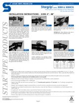
AMERICAN Flow Control has incorporated many innovative
design changes that prolong service life for swing check
valves in water and sewage service. AMERICAN Flow Control
SERIES 52-SC swing check valves are available in standard
congurations, with lever and spring or with lever and weight.

AMERICAN Flow Control
Page 7B-3
SERIES 52-SC SWING CHECK VALVE
SERIES 52-SC FEATURES AND BENEFITS
AMERICAN Flow Control has incorporated signicant
design changes to prolong service life for swing check
valves in water and sewage service. AMERICAN Flow
Control 52-SC swing check valves incorporate the
following design features to increase service life.
BODIES AND BONNETS
Valve bodies and bonnets are made of gray cast iron.
Internal contours are specically designed to provide a
smooth ow passage and reduce head loss through the
valve. The entire clapper arm and disc assembly can be
removed through the bonnet opening while the valve is
installed in the line.
CLAPPER ARMS
The clapper arms are made of impact resistant ductile
iron. The area through which the clapper arm shaft and
in which the disc stud is attached, contain bushings for
improved wear and corrosion resistance.
CLAPPER ARM SHAFTS
The clapper arm shafts are made of corrosion
resistant stainless steel for strength and durability.
RETAINING PLUGS
The clapper arm shaft is held in place by corrosion
resistant bronze retaining plugs. The plugs also act
as a wear-resistant bearings for the clapper arm
assembly. The unique design allows for easy removal
and disassembly of internal parts, should the need arise.
DISCS
Discs on check valves 4 in. and larger are made of gray
iron with bronze seat rings securely fastened into grooves
machined in the disc. The connection between the disc
and clapper arm is designed with sucient clearance to
allow the disc to adjust to the seat.
AMERICAN Flow Control 52-SC Swing Check Valves
have these features:
● Gray Cast Iron Valve Bodies
● Comply with ANSI/AWWA C508
● Stainless Steel Clapper Arm Shafts
● Full Size Waterway
● Solid Ductile Iron Clapper Arm
● Bronze Retaining Plugs
● Optional Fusion-Bonded Epoxy Coating
Inside and Out
● Certied to NSF/ANSI Standard 61 and NSF/ANSI 372

AMERICAN Flow Control Page 7B-4
SERIES 52-SC SWING CHECK VALVE
SERIES 52-SC SPECIFICATIONS
Swing check valves shall be manufactured from gray cast
iron meeting or exceeding ASTM A126 Grade B. Valves shall
comply with ANSI/AWWA C508, latest revision. Valves
shall be designed to permit an adequate waterway
opening for utilization of pipeline cleaning apparatus.
Disassembly of valve internals to require no special tools
other than standard socket wrenches. Clapper arm shall
be made of ductile iron conforming to ASTM A536.
Check valve shafts are to be constructed stainless
steel with corrosion-resistant bronze bearings provided
at each end. Shaft and bearings are to be completely
replaceable, if necessary, with valve remaining in the
pipeline. If the valve shaft is extended outside the body,
a double O-ring seal fully contained within the shaft
bearing shall be provided. There shall be a grease tting
for lubrication between the O-rings for double
protection against foreign matter reaching bearing
surfaces. Dierent lever orientation shall be possible in
the eld in increments of 45° without shaft
modications or extra drilling.
Check valve seating surfaces shall be bronze. Valve de-
sign shall be such that the valve remains in the closed
position when installed in horizontal pipeline under no-
ow condition.
Check valves to be AMERICAN Flow Control 52-SC
Swing Check Valves.

AMERICAN Flow Control Page 7B-5
SERIES 52-SC SWING CHECK VALVE
SERIES 52-SC STANDARD DIMENSIONS
Valve Size A B C D E M Y
3” 11.00 7.50 .75 6.00 4 - 0.75 7.88 7.38
4’ 13.00 9.00 .94 7.50 8 - 0.75 9.00 9.00
6” 16.00 11.00 1.00 9.50 8 - 0.88 11.75 10.75
8” 19.50 13.50 1.13 11.75 8 - 0.88 14.25 12.75
10” 24.50 16.00 1.19 14.25 12 - 1.00 16.38 14.75
12” 27.50 19.00 1.25 17.00 12 - 1.00 18.75 18.00
14” 31.00 21.00 1.38 18.75 12 - 1.13 22.50 20.38
16” 36.00 23.50 1.44 21.25 16 - 1.13 24.50 21.75

AMERICAN Flow Control Page 7B-6
SERIES 52-SC SWING CHECK VALVE
Valve Size A B C D E H L M Y
3” 11.00 7.50 .75 6.00 4 - 0.75 8.50 5.85 3.94 7.38
4’ 13.00 9.00 .94 7.50 8 - 0.75 9.50 6.57 4.50 9.00
6” 16.00 11.00 1.00 9.50 8 - 0.88 11.13 9.43 5.88 10.75
8” 19.50 13.50 1.13 11.75 8 - 0.88 14.13 10.66 7.13 12.75
10” 24.50 16.00 1.19 14.25 12 - 1.00 15.00 12.35 8.19 14.75
12” 27.50 19.00 1.25 17.00 12 - 1.00 15.00 13.01 9.38 18.00
14” 31.00 21.00 1.38 18.75 12 - 1.13 16.00 15.56 11.25 20.38
16” 36.00 23.50 1.44 21.25 16 - 1.13 18.00 16.96 12.25 21.75
SERIES 52-SC LEVER AND WEIGHT DIMENSIONS

AMERICAN Flow Control Page 7B-7
SERIES 52-SC SWING CHECK VALVE
SERIES 52-SC LEVER AND SPRING DIMENSIONS
Valve Size A B C D E K M Y
3” 11.00 7.50 .75 6.00 4 - 0.75 5.35 3.94 7.38
4” 13.00 9.00 .94 7.50 8 - 0.75 6.06 4.50 9.00
6” 16.00 11.00 1.00 9.50 8 - 0.88 8.68 5.88 10.75
8” 19.50 13.50 1.13 11.75 8 - 0.88 9.66 7.13 12.75
10” 24.50 16.00 1.19 14.25 12 - 1.00 11.16 8.19 14.75
12” 27.50 19.00 1.25 17.00 12 - 1.00 11.82 9.38 18.00
14” 31.00 21.00 1.38 18.75 12 - 1.12 13.94 11.25 20.38
16” 36.00 23.50 1.44 21.25 16 - 1.12 15.33 12.25 21.75

AMERICAN Flow Control
Page 7B-8
SERIES 52-SC SWING CHECK VALVE
SERIES 52-SC OPTIONAL TAP LOCATIONS
Valve Size Maximum Tap Size for Bosses
A, B, C, E, F, & G
3” 1/2 NPT
4” 3/4 NPT
6” 1 NPT
8” 1 NPT
10” 2 NPT
12” 2 NPT
14” 2 NPT
16 2 NPT

AMERICAN Flow Control Page 7B-9
SERIES 52-SC SWING CHECK VALVE
SERIES 52-SC WEIGHTS
Valve Size Standard Lever / Spring Lever / Weight
3” 61 63 64
4” 98 102 104
6” 167 170 173
8” 274 288 295
10” 445 450 470
12” 620 655 655
14” 1010 1080 1080
16’ 1180 1250 1250
NOTE: All weights are in pounds

AMERICAN Flow Control Page 7B-10
SERIES 52-SC SWING CHECK VALVE
AMERICAN Flow Control
SERIES 52-SC SWING CHECK VALVE
SUBMITTAL SHEET
QTY
3” 4” 6” 8” 10” 12” 14” 16”
Type (Check One)
Standard
Lever and Weight
Lever and Spring
Face (Check One)
Bronze Faced Disc
Rubber Faced Disc (3” - 10”)
Optional Body Tap: Size
Location
Other Requirements (List):
AMERICAN Flow Control
American-Darling Valve and Waterous
A Division of AMERICAN
NOTES:
1. Series 52-SC valves meet or exceed requirements of ANSI/AWWA C508.
2. 3 in.–12 in. valves have 200 psig rated working pressure.
3. 14 in. and 16 in. valves have 150 psig rated working pressure.
Visit our web site at http://www.american-usa.com/afc

AMERICAN Flow Control Page 7B-11
SERIES 52-SC SWING CHECK VALVE
SERIES 52-SC INSTALLATION AND MAINTENANCE
INSTALLATION
This information is provided as a recommendation to
the customer for the proper use and installation of swing
check valves.
When received, the valves should be unloaded carefully
and in the case of Series 52-SC, stored with clapper
braced in closed position. If provided, leave end protectors
in place after initial examination. Protect stored valves
from the elements and from undue damage in handling.
At the time of installation, remove any bracing from the
swing check valve. Make sure the valve and ange
gasket surfaces are clean and free of damage. Clean
the inside of the valve to remove all debris and/or
contaminants that may aect performance, or uid
quality. Check for free movement of clapper and inspect
valve seal. Check the direction of ow in the pipeline
and make sure the arrow cast on the side of the valve
body agrees with the direction of ow through the valve.
Valves without lever and weight, or spring, are to be
installed with the centerline of the valve port in a horizontal
position and with the bonnet facing upward. Check
valves will operate satisfactorily if not oriented more
than 45° from the horizontal and with the ow upward.
To help prevent check valve slam, the valve can be supplied
with an optional extended shaft conguration, equipped with
either lever and weight, or lever and spring. The principle
behind either of these options is to close the valve before
the uid establishes a reverse ow. The torque required to
close the valve is unique to each system. The torque can
be adjusted by changing the number and position of the
spring and/or weight. In any service where the possibility
of slamming exists, it is recommended that check valves
be equipped with lever and spring, or lever and weight.
Check valves equipped with lever and spring can be used in
a horizontal pipeline or in a vertical pipeline only when ow
is upward. Check valves equipped with lever and weight
can also be used in either a horizontal pipeline or a vertical
pipeline. The lever must be positioned correctly to achieve
valve closure. In the case of the Series 52-SC, the correct
position of the lever and weight, when valve is installed in
a horizontal line is 45° below the horizontal centerline of
pipe, on the downstream side of the check valve disc. If the
check valve is to be installed in a vertical line with upward
ow, the lever should be moved 90° counterclockwise from
this position. The Series 600 is equipped with two keyways:
one for horizontal waterway and one for a vertical waterway.
Check valves should be installed in accordance with
Standard Practice MSS SP-92.
DO NOT INSTALL CHECK VALVES IN A VERTICAL
LINE WITH DOWNWARD FLOW.
At the time of installation, make sure piping is properly
aligned and supported to avoid stress on the valve
body. Under no circumstances should the installation
of the valve be used to correct alignment errors.
TESTING
Check to see that all valve joints and pressure-containing
bolts are tight. After testing, relieve excess pressure from
the upstream side of the valve.
1.
2.
3.
4.
5.
6.
7.
8.
OPERATION
On swing check valves without lever or weight,
there are no special instructions regarding the
operation since the valve is actuated by line ow.
If supplied with a lever or weight, the check valve can be
adjusted to counteract slamming and/or surge. Adjustment
may be accomplished by adjusting the tension on the spring,
or the position, and/or amount, of weight on the valve.
1.
2.
SPARE PARTS
Under most conditions the only spare parts needed for
swing check valves would be bonnet gasket, and any
applicable retaining plug gaskets and O-rings, if valve is
equipped with extended shaft. Under conditions where
very frequent oscillation of a clapper is experienced, and/or
sever, service conditions, other parts may be kept in stock.
MAINTENANCE
Normally there is very little maintenance on a check valve.
On standard check valves it is suggested the valve be
disassembled once a year. Depressurize the valve for
inspection. Check for wear at all oscillating locations.
On the Series 52-SC Check Valves with extended shaft
valves, every six months add an AMERICAN Flow Control
recommended grease between O-rings until resistance to
ow is felt on the grease gun lever. If leakage occurs due
to oscillation, replace O-rings by removing retainer plug.
Be sure to pressurize space between o-rings with grease
after reassembly. Look for excessive wear on extended
shaft and bearing bore that would prevent O-ring sealing.
1.
2.
WARNING: Special care should be taken in the
installation, inspection and repair of pressure
containing devices such as valves and hydrants.
FAILURE TO FOLLOW PROPER PRACTICE AND
GUIDELINES CAN RESULT IN SERIOUS INJURY OR
DEATH. Do not make repairs while check valve is
under pressure.

SERIES 52-SC SWING CHECK VALVE
Page 7B-12AMERICAN Flow Control
SERIES 52-SC STANDARD PARTS LIST
Ref. No. Description Material Quantity
1 Bonnet Gray Iron (See Note 4) 1
2 Bonnet Bolt & Nut 0304 Stainless Steel Varies
3 Bonnet Gasket Composition Rubber 1
4-2 Flanged End Case Gray Iron (See Note 4) 1
5 Disc See Note 5 1
6 Disc Stud Bronze 1
7 Clapper Arm Ductile Iron 1
8 Clapper Arm Shaft Stainless Steel 1
9 Retainer Plug Bronze 2
10 Retainer Plug Gasket Composition Rubber 2
13 Seat Ring Bronze 1
28 Shaft Bushing Bronze (See Note 6) 1
29 Disc Stud Bushing Bronze 1
NOTES:
1. Construction, materials and testing comply with ANSI/AWWA C508.
2. Bolt patterns of Class 125 anged ends are in accordance with ANSI/AWWA C110/A21.10 (ASME B16.1 Class 125).
3. Valves have manufacturer’s name, pressure class and year of manufacture cast on side of case.
4. All gray iron is ASTM A126 Class B.
5. Discs on 3 in. are bronze, 4 in. and above are gray iron with bronze face disc that has lug on O.D. to prevent rotation.
6. Shaft bushings for valves 3 in.–10 in. are bronze, 12 in.–16 in. are nylon with molybdenum disulphide uniformly dispersed.

SERIES 52-SC SWING CHECK VALVE
Page 7B-13AMERICAN Flow Control
SERIES 52-SC LEVER AND WEIGHT PARTS LIST
Ref.
No.
Description Material Qty.
1 Bonnet Gray Iron 1
2 Bonnet Bolt & Nut 0304 Stainless Steel Varies
3 Bonnet Gasket Composition Rubber 1
4-2 Flanged Ends Case Gray Iron 1
5 Disc (See Note 6) 1
6 Disc Stud Bronze 1
7-1 Clapper Arm for Lever Ductile Iron 1
8-1 Clapper Arm Shaft Assembly Stainless Steel (See Note 5) 1
9 Retainer Plug Bronze 1
9-1 Retainer Plug for Lever Bronze 1
10 Retainer Plug Gasket Composition Rubber 2
13 Seat Ring Bronze 1
20 Shaft Key Stainless Steel 1
25 Weight for Lever Gray Iron 1
26 O-ring Rubber 2
27 Weight Set Screw Steel 1
29 Disc Stud Bushing Bronze 1
32-7 Grease Fitting Steel 1
41 Lever Ductile Iron 1
41-1 Lever Bolt 0304 Stainless Steel 1
41-2 Lever Washer 0304 Stainless Steel 1
Construction, materials and testing comply with
ANSI/AWWA C508.
Bolt patterns of Class 125 anged ends are in
accordance with ANSI/AWWA C110/A21.10
(ASME B16.1 Class 125).
Valves have manufacturer’s name, pres-sure
class and year of manufacture cast on side of
case.
All gray iron is ASTM A126 Class B.
Clapper Arm shaft is stainless steel. As-sembly
includes lever, bolt, washer and key.
Disc on 3 in. is bronze. 4 in. and above are
gray iron with bronze face. Disc has lug on O.D.
to prevent rotation.
Lever is furnished on side and position shown
unless otherwise specied. Lever shown by dot
and dash lines is the position furnished when
valve is to be installed in a vertical line with
upward ow for lever and weight.
1.
2.
3.
4.
5.
6.
7.

AMERICAN Flow Control
Page 7B-14
SERIES 52-SC SWING CHECK VALVE
SERIES 52-SC LEVER AND SPRING PARTS LIST
Ref.
No.
Description Material Qty.
1 Bonnet Gray Iron 1
2 Bonnet Bolt & Nut 0304 Stainless Steel Varies
3 Bonnet Gasket Composition Rubber 1
4-2 Flanged Ends Case Gray Iron 1
5 Disc (See Note 6) 1
6 Disc Stud Bronze 1
7-1 Clapper Arm for Lever Ductile Iron 1
8-1 Clapper Arm Shaft Assembly Stainless Steel (See Note 5) 1
9 Retainer Plug Bronze 1
9-1 Retainer Plug for Lever Bronze 1
10 Retainer Plug Gasket Composition Rubber 2
13 Seat Ring Bronze 1
19-1 Bracket Cap Screw Steel 1
20 Shaft Key Stainless Steel 1
21 Spring Bracket Steel 1
22 Spring Link Plated Steel 1
23 Link Nut Plated Steel 2
24 Spring for Lever Steel 1
26 O-ring Rubber 2
29 Disc Stud Bushing Bronze 1
32-7 Grease Fitting Steel 1
41 Lever Ductile Iron 1
41-1 Lever Bolt 0304 Stainless Steel 1
41-2 Lever Washer 0304 Stainless Steel 1
Construction, materials and testing comply with
ANSI/AWWA C508.
Bolt patterns of Class 125 anged ends are in
accordance with ANSI/AWWA C110/A21.10
(ASME B16.1 Class 125).
Valves have manufacturer’s name, pressure
class and year of manufacture cast on side of
case.
All gray iron is ASTM A126 Class B.
Clapper Arm shaft is stainless steel. Assembly
includes lever, bolt, washer and key.
Disc on 3 in. is bronze. 4 in. and above are
gray iron with bronze face. Disc has lug on O.D.
to prevent rotation.
Lever is furnished on side and position shown
unless otherwise specied.
1.
2.
3.
4.
5.
6.
7.
/