Page is loading ...

VAL-MATIC® VALVE AND MANUFACTURING CORP.
905 Riverside Dr. ● Elmhurst, IL 60126
Phone (630) 941-7600 ● Fax (630) 941-8042
www.valmatic.com
Manual No.
SCV-OM2-0
Threaded
Silent Check Valve
Operation, Maintenance and
Installation Manual
INTRODUCTION ........................................... 1
RECEIVING AND STORAGE ........................ 1
DESCRIPTION OF OPERATION .................. 1
INSTALLATION ............................................. 1
VALVE CONSTRUCTION ............................. 2
MAINTENANCE ............................................. 2
TROUBLESHOOTING ................................... 2
DISASSEMBLY .............................................. 3
REASSEMBLY ............................................... 3
PARTS AND SERVICE .................................. 3
WARRANTY .................................................. 4

1
THREADED STYLE SILENT CHECK VALVE
OPERATION, MAINTENANCE AND INSTALLATION
INTRODUCTION
This manual will provide you with the information to
properly install and maintain the valve to ensure a
long service life. The Threaded Silent Check Valve
is ruggedly constructed of lead-free bronze to give
years of trouble free operation. The valve should be
installed in horizontal or vertical pipes carrying clean
water.
The Threaded Silent Check Valve is designed to
open fully to provide flow in the forward direction and
close rapidly upon flow reversal. The valves are
used to prevent reverse flow through pumps or in
piping systems. The size and cold working pressure
(250 CWP) are marked on the body for reference.
This valve is not intended for fluids containing
suspended solids such as wastewater.
RECEIVING AND STORAGE
Inspect valves upon receipt for damage in shipment.
The valves should remain boxed, clean and dry until
installed to prevent weather related damage. For
long term storage, no special provisions are needed.
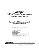
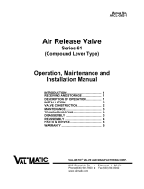
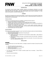
DESCRIPTION OF OPERATION
The Threaded Silent Check Valve is designed to
prevent reverse flow automatically. On pump start-
up, the flow of water enters the valve from the seat
end (right side in Figure 1) and forces the disc open,
allowing the passage of fluid through the valve.
On pump shut-down, the spring closes the disc
rapidly before a flow reversal takes place. This type
of closure, which prevents flow reversal, is the factor
which provides “silent” operation and reduces water
hammer associated with check valve slam.
The valve body is supplied with NPT tapered
threads on each end for installation in pipelines.
FIGURE 1. THREADED SILENT CHECK VALVE
INSTALLATION
The installation of the valve is important for its
proper operation. The flow arrow on the valve body
must point in the direction of flow when the system is
in operation. The valve can be installed in horizontal
or vertical lines with the flow up or down.
Three diameters of straight pipe upstream of the
valve are recommended to prevent turbulent flow
streams through the valve, which can cause
vibration and wear.
When installed in horizontal lines, the check valve
does not have a specific upward orientation. Insert
pipe nipples with thread sealant or thread tape and
tighten while securing valve with a wrench on the
body end nearest the pipe nipple.
CAUTION
The use of excessive torque can damage the
valve.
CAUTION
This valve is not intended for fluids
containing suspended solids or hazardous
fluids.

2
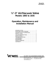
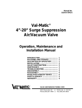
VALVE CONSTRUCTION
The standard threaded check valve body (1) is
constructed of lead-free bronze and is certified to
comply with NSF/ANSI 372, “Drinking Water System
Components – Lead Content.” The internal metal
components are bronze or stainless steel. The body
(1) is threaded and designed to accept pipe nipples
with NPT pipe threads. The disc (3) and spring (4)
are the only moving parts and require no
maintenance or lubrication. The general details of
construction are illustrated in Figure 2.
FIGURE 2. VALVE CONSTRUCTION
TABLE 1. CHECK VALVE PARTS LIST
MAINTENANCE
Threaded Silent Check Valves require no scheduled
lubrication or maintenance.
INSPECTION: Periodic inspection for leakage can
be performed by listening for leakage noise from the
valve while the pump is shut down. If leakage is
heard, drain the pipeline, remove the valve, and
inspect the seating surfaces for wear or mineral
deposits. Clean or replace the valve as needed.
TROUBLESHOOTING
Several problems and solutions are presented below
to assist you in troubleshooting the valve assembly
in an efficient manner.
Valve Chatters or Vibrates: Verify that velocity
is at least 4 feet per second. Noise sounding
like rocks in the line can be cavitation due to
high velocities, low downstream pressure, or an
upstream expanded. Verify that there are three
diameters of straight pipe upstream.
Valve Leakage: Drain line, remove valve, and
inspect seating surfaces for debris or damage. If
body washer is leaking, apply torque to the two
body pieces.
Valve Does Not Pass Flow: Check flow arrow
direction on valve body. Verify that downstream
isolation valve is open and there is no line
blockage downstream.
Valve Slams: Remove valve and inspect spring.
ITEM DESCRIPTION MATERIAL
1 Body Lead Free Bronze
2 Seat Teflon
3 Disc Lead Free Bronze
4 Spring Stainless Steel
6 Seat Screw Lead Free Bronze
Spare Parts are not available for this valve.
A replacement valve is recommended.

3
DISASSEMBLY
The valve should be removed from the pipeline for
disassembly. A skilled mechanic with proper tools
should perform all work on the valve. Refer to
Figure 2.
1. Clamp the downstream end of the valve body
(1) lightly in a vise using the hex connection
on the valve body. Do not over-clamp the
valve or permanent distortion and leakage
may occur. Remove the seat end of the valve
using a wrench on the hex ends and unthread
the body seat in a counterclockwise direction.
2. Lift up the disc assembly (3) from the body.
3. Examine the Teflon seat (2) and inspect the
mating body seating surface for damage.
Some minor dents and discoloration are
normal. Grooves or wear areas will cause
leakage and requires valve replacement.
4. Remove spring (4) and check for wear or
cracks.
REASSEMBLY
All parts must be clean and gasket surfaces should
be cleaned with a stiff wire brush in the direction of
the serrations or machine marks. Worn parts,
gaskets, and seals should be replaced during
reassembly.
1. Insert spring (5) into body (1).
2. Lay disc (3) over the spring.
3. Install the seat half of the body making sure
that the body washer (5) is in place. Tighten
the body pieces as a minimum to the torques
shown in Table 2. If leakage is found during
operation, elevate the torques until leakage
stops.
Body Assembly Torque
Valve Size Torque
1/2” 50 ft-lbs
3/4” 75 ft-lbs
1” 100 ft-lbs
1-1/4” 125 ft-lbs
1-1/2” 150 ft-lbs
2” 200 ft-lbs
TABLE 2. ASSEMBLY TORQUES
PARTS AND SERVICE
Parts and service are available from your local
representative or the factory. Make note of the
Valve Size and Model Number located on the valve
nameplate and contact:
Val-Matic Valve and Manufacturing Corp.
905 Riverside Drive
Elmhurst, IL 60126
Phone: (630) 941-7600
Fax: (630) 941-8042
www.valmatic.com
A sales representative will quote prices for parts or
arrange for service as needed.
WARNING
The line must be drained before removing
the valve or pressure may be released
causing injury.

4
LIMITED WARRANTY
All products are warranted to be free of defects in material and workmanship for a period of one year from the date
of shipment, subject to the limitations below.
If the purchaser believes a product is defective, the purchaser shall: (a) Notify the manufacturer, state the alleged
defect and request permission to return the product; (b) if permission is given, return the product with
transportation prepaid. If the product is accepted for return and found to be defective, the manufacturer will, at his
discretion, either repair or replace the product, f.o.b. factory, within 60 days of receipt, or refund the purchase
price. Other than to repair, replace or refund as described above, purchaser agrees that manufacturer shall not be
liable for any loss, costs, expenses or damages of any kind arising out of the product, its use, installation or
replacement, labeling, instructions, information or technical data of any kind, description of product use, sample or
model, warnings or lack of any of the foregoing. NO OTHER WARRANTIES, WRITTEN OR ORAL, EXPRESS
OR IMPLIED, INCLUDING THE WARRANTIES OF FITNESS FOR A PARTICULAR PURPOSE AND
MERCHANTABILITY, ARE MADE OR AUTHORIZED. NO AFFIRMATION OF FACT, PROMISE, DESCRIPTION
OF PRODUCT OF USE OR SAMPLE OR MODEL SHALL CREATE ANY WARRANTY FROM MANUFACTURER,
UNLESS SIGNED BY THE PRESIDENT OF THE MANUFACTURER. These products are not manufactured, sold
or intended for personal, family or household purposes.
VAL-MATIC® VALVE AND MANUFACTURING CORP.
905 Riverside Dr. ● Elmhurst, IL 60126
Phone (630) 941-7600 ● Fax (630) 941-8042
www.valmatic.com
/