Page is loading ...

Manual No.
ARCO-OM2-2
Val-Matic
®
6”-8” Combination Air Valve
(Single Housing Type)
Operation, Maintenance and
Installation Manual
INTRODUCTION ......................................... 1
RECEIVING AND STORAGE ...................... 1
DESCRIPTION OF OPERATION ................ 1
INSTALLATION .......................................... 2
VALVE CONSTRUCTION ........................... 2
MAINTENANCE .......................................... 4
TROUBLESHOOTING ................................ 4
DISASSEMBLY ........................................... 4
REASSEMBLY ............................................ 5
PARTS & SERVICE .................................... 5
WARRANTY ................................................ 6
VAL-MATIC
®
VALVE AND MANUFACTURING CORP.
905 Riverside Dr. ● Elmhurst, IL 60126
Phone (630) 941-7600 ● Fax (630) 941-8042
www.valmatic.com

1
VAL-MATICS 6”-8” COMBINATION AIR VALVE
OPERATION, MAINTENANCE AND INSTALLATION
INTRODUCTION
This manual will provide you with the information
to properly install and maintain the valve to
ensure a long service life. The valve has been
designed with stainless steel trim to give years
of trouble free operation. The Combination Air
Valve is typically mounted at the high points in a
piping system and performs the functions of both
an air release valve and an air/vacuum valve.
The Combination Air Valve automatically vents
air, which accumulates at high points in a
system during its operation. The valve will also
exhaust and admit large quantities (volumes) of
air during filling or draining operations and after
emergency conditions such as a power failure.
Both the air release and air/vacuum functions
are needed to maintain pipeline efficiency while
providing protection from adverse pressure
conditions.
Note: This valve is not intended for fluids
containing suspended solids such as
wastewater. For wastewater and other high
turbidity applications, use Val-Matic Series 800
Wastewater Combination Air Valves.
The valve is a float operated, resilient seated
valve designed to handle clean fluids. The
Maximum Working Pressure and Model No. are
stamped on the nameplate for reference.
Note: Low Durometer seats are available for low
pressure applications.
RECEIVING AND STORAGE
Inspect valves upon receipt for damage in
shipment. Handle all valves carefully without
dropping. Valves should remain boxed, clean
and dry until installed to prevent weather related
damage. For long term storage greater than six
months, the valve must remain in the box and
stored indoors. Do no expose valve to sunlight
or ozone for an extended period.
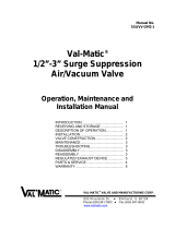
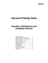
Figure 1. 6”-8” Combination Air Valve
DESCRIPTION OF OPERATION
The Combination Air Valve is fully automatic and
designed to continuously remove air
accumulating at the high points in a piping
system. It also will exhaust and admit air during
filling and draining of the pipeline or tank.
The valve consists of an air/vacuum valve
mechanism with a full size outlet and an air
release valve mechanism with a small diameter
(i.e. 3/8”) precision orifice. The combination air
valve as shown is Figure 1 is a normally open
valve and has three functions as follows.
CAUTION
This valve is not intended for fuel service
or fluids containing suspended solids.

2
1. During system startup, the open valve
will exhaust large volumes of air through
the large outlet. When fluid enters the
valve, the air/vacuum float will rise and
seal against the seat. At the same time
the round float will rise and press the
orifice button against the air release
orifice. The air/vacuum float will remain
closed until the pressure drops close to
zero.
2. As air accumulates in the piping system
and enters the valve, the round float
drops and the orifice button breaks
contact with the small orifice.
Accumulated air will vent through the
small outlet in the valve cover while the
system is under pressure. As all of the
air is vented, the round float rises again
and closes the orifice button.
3. When the piping system is drained, both
floats will drop and allow air to rapidly
reenter the piping system through both
the air/vacuum and air release orifices.
INSTALLATION
The installation of the valve is important for its
proper operation. Valves must be installed at
the system high points in the vertical position
with the inlet down. For pipeline service, a vault
with freeze protection, adequate screened
venting, and drainage should be provided.
During closure, some fluid discharge will occur
so vent lines should extend to an open drain
area in plant service. A shutoff valve should be
installed below the valve in the event servicing is
required.
Flanges should be mated with flat-faced pipe
flanges equipped with resilient gaskets. Flange
bolts should be lubricated and lightly turned until
all gaps are eliminated. The tightening of the
bolts should then be done in graduated steps
using the crossover tightening method. 3/4”
bolts require a torque of 40-150 ft-lbs. 7/8” bolts
(model 258C) require a torque of 45-205 ft-lbs.
If leakage occurs, allow gaskets to absorb fluid
and check torque and leakage in 24 hours. Do
not exceed bolt rating or crush gasket more than
50% of its thickness.
VALVE CONSTRUCTION
The standard Combination Air Valve body and
cover are cast iron. See specific Materials List
submitted for the order if other than standard
cast iron construction. The internal metal
components are stainless steel. The orifice
button and seat are resilient Buna-N. The
general details of construction are illustrated in
Figure 2. The body (1) is flanged for connection
to the pipeline. The air/vacuum seat (4) is
retained by retaining screws (8) in the cover (2).
The air release seat (4A) is threaded into the
cover (2) and sealed with the adjustable orifice
button (11), which has a threaded post for
attachment to the orifice button arm (22).

3
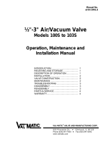
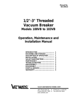
Figure 2. 6”-8” Combination Air Valve
Item Description Material Item Description Material
1 Body Cast Iron 11 Orifice Button* Buna-N
2 Cover Cast Iron 12 Pivot Pin* Stainless Steel
3 Leverage Frame* Stainless Steel 13 Retaining Ring* Stainless Steel
4 Seat* Buna-N 15 Cushion* Buna-N
4A Seat* Stainless Steel 17 Float Retainer* Stainless Steel
5 Float* Stainless Steel 18 Lock Nut* Stainless Steel
5A Float* Stainless Steel 19 Link* Stainless Steel
6 Gasket* Non-Asbestos 21 Locating Pin* Stainless Steel
7 Cover Bolt Alloy Steel 22 Orifice Button Arm* Stainless Steel
8 Retaining Screw* Stainless Steel 23 Hood Assembly Steel
8A Retaining Screw* Stainless Steel 28 Pipe Plug Steel
9 Guide Bushing* Stainless Steel 30 Washer* Stainless Steel
10 Float Arm* Stainless Steel 34 Lock Washer* Stainless Steel
*Recommended Repair Part Kit
Table 1. Combination Air Valve Parts List

4
MAINTENANCE
The Combination Valve requires no scheduled
lubrication or maintenance.
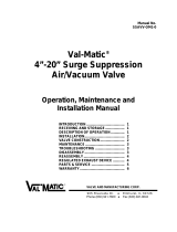
INSPECTION: Periodic inspection for leakage
can be performed. A manual drain valve can be
installed in the lower drain plug to perform this
operation as shown in figure 3.
1. With the inlet shutoff valve open, partially
open the drain valve until flow can be heard.
If the air valve is working properly, water
should be exhausted from the drain valve. If
air is exhausted, follow steps 2-6.
2. Close the inlet shutoff valve.
3. Slowly open the drain valve to allow the fluid
in the valve to drain.
4. Close the drain valve.
5. Slowly open the inlet shutoff valve to fill the
valve with water. Observe the seating action
and verify that the valve closes without
leakage.
6. If leakage occurs, the valve should be
removed and inspected for wear or possible
damage from foreign matter.
Figure 3. Inspection Piping
TROUBLESHOOTING
Several problems and solutions are presented
below to assist you in troubleshooting the valve
assembly in an efficient manner.
1. Leakage at Bottom Connection: Tighten
valve flanged connection. If leak persists,
remove valve and replace gasket.
2. Leakage at Cover: Tighten bolts to 150 ft-lbs,
replace gasket.
3. Valve Leaks when Closed: Flush valve to
remove debris. Disassemble and inspect
seats, orifice button and floats. NOTE: Many
floats contain sand for weight but if water is
detected, replace float.
4. Valve Not Venting Air: Check that operating
pressure does not exceed Working Pressure
on nameplate. Perform inspection steps 2-6
and disassemble valve if problem persists.
DISSASSEMBLY
The valve can be disassembled without
removing it from the pipeline. Or for
convenience, the valve can be removed from the
line. All work on the valve should be performed
by a skilled mechanic with proper tools. No
special tools are required.
1. Close inlet shutoff valve. Open drain valve or
remove drain plug. Remove hood if needed.
Remove the cover bolts (7) on the top cover.
2. Pry cover (2) loose and lift off valve body.
Both float mechanisms will remain attached
to the cover.
3. Remove the retainer rings (13) and pivot pins
(12) that pass through the float arm (10) and
orifice button arm (22).
4. Remove retaining screws (8A) and lever
frame (3). Remove orifice (4A) from cover
(2).
5. Remove locknut (18) and orifice button (11)
from orifice button arm (22).
6. Remove retaining screws (8).
7. Lift float (5) from body (1). Remove cushion
(15) and guide bushings (9) which are
threaded into the body (1) and cover (2).
8. Clean and inspect all parts. Note: Some
floats contain sand for extra weight; if water is
detected, replace float. Replace worn parts
as necessary and lubricate parts with FDA
grease. Remove all foreign matter from body
and cover.
WARNING
The valve must be drained before
removing the cover or pressure may be
released causing injury.

5
REASSEMBLY
All parts must be cleaned and gasket surfaces
should be cleaned with a stiff wire brush in the
direction of the serrations or machine marks.
Worn parts, gaskets and seals should be
replaced during reassembly. Refer to Figure 2.
1. Lay cover on flat surface with outlet faced
down. Lay seat (4) in machined recess and
fasten with sleeves (26) and 5/16” retaining
screws (8). Tighten to a maximum of 5 ft-lbs.
2. Apply Loctite 680 to guide bushings (9) and
thread into cover (2) and body (1).
3. Apply Loctite PST pipe sealant to seat (4A)
and thread into cover (2).
4. Assemble float (5A) to float arm (10) using
float retainer screw (17) and Loctite 680 with
Primer T.
5. Assemble lever frame assembly to cover (2)
with screws (8A) and locating pin (21).
6. Attach lever frame assembly to cover (2) with
screws (8A) and locating pin (21).
7. Screw new orifice button (11) into arm (10)
with lock washer (34) and locknut (18). Do
not tighten nut at this time.
8. Adjust orifice button so that when it is in light
contact with the seat (4A), the arm (10)
slopes away from the cover about 1/16”.
Lock orifice button with lock nut (18).
9. Install new cushion (15) in body and lower
float (5) into body baffle.
10. Lay new cover gasket on clean surface and
apply a gasket compound such as Permatex
#80065 to both surfaces. Assemble gasket
(6) and cover (2) over boltholes in body (1).
11. Insert lubricated 3/4" cover bolts (7) and
tighten to 150 ft-lbs.
12. Place valve back in service. Refer to the
Installation instructions on page 2. Slowly
open inlet isolation valve.
PARTS AND SERVICE
Parts and service are available from your local
representative or the factory. Make note of the
valve Size and Model No. located on the valve
nameplate and contact:
Val-Matic Valve and Mfg. Corp.
905 Riverside Drive
Elmhurst, IL 60126
Phone: (630) 941-7600
Fax: (630) 941-8042
www.valmatic.com
A sales representative will quote prices for parts
or arrange for service as needed.

6
VAL-MATIC
®
VALVE AND MANUFACTURING CORP.
905 Riverside Dr. ● Elmhurst, IL 60126
Phone (630) 941-7600 ● Fax (630) 941-8042
www.valmatic.com
LIMITED WARRANTY
All products are warranted to be free of defects in material and workmanship for a period of one year from the date of
shipment, subject to the limitations below.
If the purchaser believes a product is defective, the purchaser shall: (a) Notify the manufacturer, state the alleged defect
and request permission to return the product; (b) if permission is given, return the product with transportation prepaid. If
the product is accepted for return and found to be defective, the manufacturer will, at his discretion, either repair or replace
the product, f.o.b. factory, within 60 days of receipt, or refund the purchase price. Other than to repair, replace or refund
as described above, purchaser agrees that manufacturer shall not be liable for any loss, costs, expenses or damages of
any kind arising out of the product, its use, installation or replacement, labeling, instructions, information or technical data
of any kind, description of product use, sample or model, warnings or lack of any of the foregoing. NO OTHER
WARRANTIES, WRITTEN OR ORAL, EXPRESS OR IMPLIED, INCLUDING THE WARRANTIES OF FITNESS FOR A
PARTICULAR PURPOSE AND MERCHANTABILITY, ARE MADE OR AUTHORIZED. NO AFFIRMATION OF FACT,
PROMISE, DESCRIPTION OF PRODUCT OF USE OR SAMPLE OR MODEL SHALL CREATE ANY WARRANTY FROM
MANUFACTURER, UNLESS SIGNED BY THE PRESIDENT OF THE MANUFACTURER. These products are not
manufactured
,
sold or intended for
p
ersonal
,
famil
y
or household
p
ur
p
oses.
/