Page is loading ...

Manual No.
VB-OM1-1
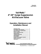
2”- 42” Flanged Vacuum Breaker
Operation, Maintenance and
Installation Manual
INTRODUCTION.................................... 1
RECEIVING AND STORAGE................. 1
DESCRIPTION OF OPERATION...........1
INSTALLATION......................................2
DRAWING SS-1381............................... 3
VALVE CONSTRUCTION...................... 5
MAINTENANCE ..................................... 5
TROUBLESHOOTING ........................... 6
DISASSEMBLY...................................... 6
REASSEMBLY....................................... 6
PARTS AND SERVICE.......................... 6
WARRANTY...........................................7
® VAL-MATIC® VALVE AND MANUFACTURING CORP.
905 RIVERSIDE DR. ELMHURST, IL. 60126
TEL. 630 / 941-7600 FAX. 630 / 941-8042

1
2 to 42 in. FLANGED VACUUM BREAKER
OPERATION, MAINTENANCE AND INSTALLATION
INTRODUCTION
This manual will provide you with the information to
properly install and maintain the vacuum breaker to
ensure a long service life. The vacuum breaker is
ruggedly constructed with bronze or stainless steel
trim to give years of trouble free operation. The
valve should be installed at high points along
horizontal pipelines or over tanks.
The Vacuum Breaker is designed to open fully and
allow air to re-enter the pipeline or system during
critical vacuum conditions in the pipe or tank caused
by power failure or rapid draining of the piping
system. The vacuum breaker will not allow air to
escape from the pipeline. An optional air release
valve can be piped to the side of the valve to release
trapped air during pipeline operation.
The size, cold working pressure, and model number
are stamped on the nameplate for reference. This
valve is not intended for fluids containing suspended
solids such as wastewater. For wastewater and
other high turbidity applications, use Val-Matic
Series 1800VBS Vacuum Breakers for Wastewater
Service.
RECEIVING AND STORAGE
Inspect valves upon receipt for damage in shipment.
Unload all valves carefully to the ground without
dropping. When lifting, the valve should be secured
by the body and never lifted by the bronze or
stainless steel trim.
The valves should remain crated, clean and dry until
installed to prevent weather related damage. For
long-term storage greater than six months, the
rubber surfaces of the seat should not be exposed to
sunlight or ozone for any extended period.
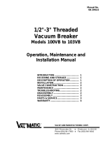
FIGURE 1. VACUUM BREAKER
DESCRIPTION OF OPERATION
The vacuum breaker is designed to prevent vacuum
conditions from occurring in pipes or tanks. After a
power failure or rapid draining of the system, a
vacuum condition often occurs in a pipe or tank.
The pressure difference between the inside vacuum
and outside air will cause a downward force on the
disc. At vacuum pressures greater than -0.25 psig,
the disc will compress the spring and move
downward allowing free flow of outside air into the
pipe or tank to eliminate the vacuum. When positive
pressure is restored in the pipe or tank, the valve will
automatically close and seal tightly. Optional valves
can be piped to the vacuum breaker to vent trapped
air in the pipeline if needed.
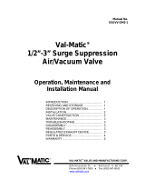
The valve may be supplied with either an optional
hooded outlet (not shown) or a flange for connection
to external piping or vent piping as shown in Figure
2. A flanged outlet is used when the valve vault is
subject to flooding or the vault cannot supply
sufficient air to the pipeline.
The only moving parts in the valve are the disc and
spring. The body bushing controls the movement of
the plug and assures that the plug contacts the seat
evenly. The valve has a resilient seal for drop tight
service.
CAUTION: This valve is not intended for
fluids containing suspended
solids or hazardous fluids.

2
FIGURE 2. VACUUM BREAKER WITH
OPTIONAL FLANGE
INSTALLATION
The installation of the valve is important for its
proper operation. The seat end must be oriented
upward. The valve should be installed on top of
horizontal lines or tanks and equipped with an
isolation valve. If installed in a vault, adequate
ventilation is needed to supply air to the vacuum
breaker.
The valve should be installed to a standard flat-face
flange per ANSI B16.5 or AWWA C207.
When used with an outlet flange, special flange
requirements are given in Drawing SS-1381 on page
3. The mating flange inside diameter must overlap
the valve seat to provide proper seat retention.
Outlet piping and companion flange are required to
retain the seat and disc. Remove the ring flange
and 2 bolts supplied with the vacuum breaker, and
replace with external, full-size flanged piping.
When mating the check valve with butterfly isolation
valves, the clearance between the butterfly disc and
the fully open check valve stem must be checked.
The location of the stem is also shown on the
vacuum breaker submittal drawings. 10 inch and
smaller vacuum breakers have sufficient clearance
for most butterfly valves. However, on 12 inch and
larger valves, the shaft extends beyond the flange
face and may interfere with the operation of adjacent
valves. A short run of pipe or spacer may be
needed between the vacuum breaker and the
isolation valve.
FLANGED ENDS: The flange should be mated with
flat-faced pipe flanges equipped with resilient
gaskets. When ring gaskets are used, the bolt
material shall be ASTM A307 Grade B or SAE
Grade 2 Carbon Steel. Higher strength bolts should
only be used with full-face gaskets.
INSTALLATION: Lower valve over mating flange
using slings or chains around the valve body.
Lubricate the flange bolts and insert them around
the flange. Lightly turn bolts until gaps are
eliminated. The tightening of the bolts should then
be done in graduated steps using the cross-over
tightening method. Recommended lubricated
torques for use with resilient gaskets (75 durometer)
are given in Table 1.
If leakage occurs, allow gaskets to absorb fluid and
check torque and leakage after 24 hours. Do not
exceed bolt rating or crush gasket more than 50 per
cent of its thickness.
125# FLANGE DATA 250# FLANGE DATA
Valve
Size
(in)
Bolt
Dia.
(in)
Bolt
Torque
(ft-lbs)
Valve
Size
(in)
Bolt
Dia.
(in)
Bolt
Torque
(ft-lbs)
2.5 5/8
25-75 2.5 3/4 25-75
3 5/8
25-75 3 3/4
35-75
4 5/8
30-90 4 3/4
50-150
5 3/4
30-90 5 3/4
70-150
6 3/4
30-90 6 3/4
70-150
8 3/4
40-120 8 7/8
90-200
10 7/8
45-150 10 1
110-300
12 7/8
65-200 12 1 1/8
160-450
14 1
80-250 14 1 1/8
140-450
16 1
90-300 16 1 1/4
180-600
18 1 1/8
100-350 18 1 1/4
190-600
20 1 1/8
120-450 20 1 1/4
220-600
24 1 1/4
150-500 24 1 1/2
350-900
30 1 1/4
180-600 30 1 3/4
500-1500
36 1 1/2
250-750 36 2
700-2000
42 1 1/2
300-900 42 2
800-2500
TABLE 1. FLANGE BOLT TORQUES
WARNING: Vacuum Breakers with Flanged
Outlets must have outlet piping
installed or damage may occur.

3

4
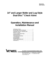
OPTIONAL AIR RELEASE VALVE: The vacuum
breaker may be furnished with an optional air
release valve as shown in Figure 3. The purpose of
the air release valve is to vent accumulated air while
the pipeline is in operation and under pressure. This
is a common application for high points on a large
water pipeline subject to column separation. In this
application the function of the vacuum breaker is to
allow large quantities of air to enter the pipeline after
power failure at the point of column separation.
Then when the columns re-unite, the air serves as a
cushion. The air is then slowly vented from the
pipeline through the air release valve.
AIR RELEASE INSTALLATION: Connect the piping
manifold and air release valve to the side of the
vacuum breaker as shown in the figure. Be sure to
open the ball valve after installation. The air release
valve will automatically close and open as needed to
vent air.
FIGURE 3. VACUUM BREAKER WITH OPTIONAL AIR RELEASE VALVE
CAUTION: The use of raised-face flanges or
excessive bolt torque may
damage valve flanges.

5
VALVE CONSTRUCTION
The standard vacuum breaker body (1) is
constructed of cast iron. See the specific Materials
List submitted for the order if other than standard
iron construction. The internal metal components
are bronze or stainless steel. The disc (3) and
spring (4) are the only moving parts and require no
maintenance or lubrication. The general details of
construction are illustrated in Figure 4.
The body (1) is flanged to connect to a pipe flange.
The seat (2) is retained in the body (1) with screws
(6) to allow assembly in the pipeline. 2-1/2” and
smaller valves have a threaded seat and no seat
screws (6). The screws will not retain the seat
against full pressure so the ring flange (10) must be
kept connected to the valve at all times. Do not
remove the ring flange while the pipeline is under
pressure or the seat (2) may become dislodged from
the body.
FIGURE 4. FLANGED VACUUM BREAKER
TABLE 2. PARTS LIST
MAINTENANCE
Vacuum Breakers require no scheduled lubrication.
MAINTENANCE: consists of keeping the outlet free
from debris on an annual basis.
INSPECTION: Periodic inspection for leakage can
be performed by inspecting the top of the valve for
accumulation of fluid. If leakage is heard, close the
isolation valve, drain the vacuum breaker
connection, remove the vacuum breaker, and
inspect the seating surfaces for wear or mineral
deposits. Clean, or repair trim as needed.
WARNING: Removal of ring flange without
draining the pipeline may cause
injury or damage to the valve.
ITEM DESCRIPTION MATERIAL
1 Body Cast Iron
2 Seat* Bronze or SS
3 Disc* Bronze or SS
(with Buna-N)
4 Spring* Stainless Steel
5 Bushing* Bronze
6 Screw* Stainless Steel
8 Gasket* Non-asbestos
10 Ring Plate Steel
11 Fastener Plated Steel
*Recommended Spare Part

6
WARNING: The line must be drained before
removing the valve or pressure
may be released causing injury.
TROUBLESHOOTING
Several problems and solutions are presented below
to assist you in trouble shooting the valve assembly
in an efficient manner.
• Valve Chatters or Vibrates: Check to see if the
pipeline operates at a regular vacuum condition.
Contact the factory about alternate spring settings.
• Valve Leakage: Check gaskets and flange bolts
for tightness. Drain line, remove valve, and
inspect seating surfaces for debris or damage. If
rubber seat (2) is damaged, then a new seat
should be installed.
• Valve Does Not Pass Flow: Verify that seat end is
up away from the pipeline or tank. Verify that
pipeline is at a vacuum condition greater than
minus 0.25 psig. Verify that isolation valve is
open and there is no line blockage downstream.
• Valve Slams: Remove valve and inspect spring.
Heavier springs can be furnished for severe high-
head applications.
DISASSEMBLY
The valve should be removed from the pipeline for
disassembly. All work on the valve should be
performed by a skilled mechanic with proper tools.
Refer to Figure 4.
1. Lay valve on flat surface or bench with the hood
facing up. 12” and larger valves require support
for the spring during disassembly.
2. Remove ring plate (10) by removing bolts and nuts
(11).
3. Remove seat retaining screws (6). Note: 2-1/2”
valves have threaded seats in lieu of retaining
screws.
4.Flip the seat (2) over and inspect the seating
surface. Some minor dents and discoloration are
normal. Grooves or wear areas will cause leakage
and requires seat replacement. Note: Replace
seat if resilient seat is worn or damaged.
5. Lift disc (3) from body. Inspect shafts and seating
surfaces for wear. The shaft diameter is normally
about 1/32” smaller in diameter than the hole in
the seat (2) and bushing (5). Some minor dents
and discoloration are normal. Wear areas will
cause leakage and require seat replacement.
Heavy mineral deposits should be removed with
lapping compound or fine sand paper.
6. Remove spring (4) and check for wear or cracks.
7. Remove bushing (5) and inspect for wear. The
inside diameter of the bushing should be about
1/32” larger in diameter than the shaft.
REASSEMBLY
All parts must be clean and gasket surfaces should
be cleaned with a stiff wire brush in the direction of
the serrations or machine marks. Worn parts,
gaskets, and seals should be replaced during
reassembly.
1. Insert bushing (5) into body (1). The bushing is
retained by the spring (4).
2. Lay spring (4) and disc (3) over bushing (5).
3. Install seat (2) with the retaining screws (6). 12”
and larger valves may require a 2x4 board and C-
clamps to compress the spring into the body.
4.Install ring plate (10) with bolts and nuts (11) and
new gasket (8).
5.Install new gaskets and valve. Tighten flange bolts
evenly using the cross-over tightening method and
the torque values given in Table 1 on page 2.
PARTS AND SERVICE
Parts and service are available from your local
representative or the factory. Make note of the
Valve Size and Model Number located on the valve
nameplate and contact:
Val-Matic Valve and Manufacturing Corp.
905 Riverside Drive
Elmhurst, IL 60126
Phone: (630) 941-7600
Fax: (630) 941-8042
www.valmatic.com
A sales representative will quote prices for parts or
arrange for service as needed.

7
LIMITED WARRANTY
All products are warranted to be free of defects in material and workmanship for a period of one year from the date of
shipment, subject to the limitations below.
If the purchaser believes a product is defective, the purchaser shall: (a) Notify the manufacturer, state the alleged defect and reques
t
permission to return the product; (b) if permission is given, return the product with transportation prepaid. If the product is accepted
for return and found to be defective, the manufacturer will, at his discretion, either repair or replace the product, f.o.b. factory, within
60 days of receipt, or refund the purchase price. Other than to repair, replace or refund as described above, purchaser agrees tha
t
manufacturer shall not be liable for any loss, costs, expenses or damages of any kind arising out of the product, its use, installation
or replacement, labeling, instructions, information or technical data of any kind, description of product use, sample or model,
warnings or lack of any of the foregoing. NO OTHER WARRANTIES, WRITTEN OR ORAL, EXPRESS OR IMPLIED, INCLUDING THE
WARRANTIES OF FITNESS FOR A PARTICULAR PURPOSE AND MERCHANTABILITY, ARE MADE OR AUTHORIZED. NO
AFFIRMATION OF FACT, PROMISE, DESCRIPTION OF PRODUCT OF USE OR SAMPLE OR MODEL SHALL CREATE ANY WARRANT
Y
FROM MANUFACTURER, UNLESS SIGNED BY THE PRESIDENT OF THE MANUFACTURER. These products are not manufactured,
sold or intended for personal, family or household purposes.
® VAL-MATIC® VALVE AND MANUFACTURING CORP.
905 RIVERSIDE DR. ELMHURST, IL. 60126
TEL. 630 / 941-7600 FAX. 630 / 941-8042
/