Page is loading ...

Manual No.
VB-OM2-0
1/2"-3" Threaded
Vacuum Breaker
Models 100VB to 103VB
Operation, Maintenance and
Installation Manual
INTRODUCTION ....................................... 1
RECEIVING AND STORAGE.................... 1
DESCRIPTION OF OPERATION.............. 1
INSTALLATION......................................... 2
VALVE CONSTRUCTION......................... 2
MAINTENANCE ........................................ 2
TROUBLESHOOTING............................... 2
DISASSEMBLY......................................... 2
REASSEMBLY.......................................... 3
PARTS & SERVICE................................... 3
WARRANTY.............................................. 4
VALVE AND MANUFACTURING CORP.
905 Riverside Dr. ● Elmhurst, IL 60126
Phone (630) 941-7600 ● Fax (630) 941-8042
www.valmatic.com

I
NTRODUCTION
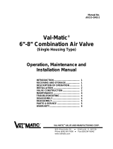
The Vacuum Breaker has been designed with
stainless steel trim to give years of trouble-free
operation. This manual will provide you with the
information to properly install and maintain the
valve to ensure a long service life. The Vacuum
Breaker is designed to open fully and allow air to
enter the piping system during critical vacuum
conditions caused by power failure or rapid
draining of the system.
NOTE: The vacuum breaker will not allow air to
escape from the pipeline. An optional air release
valve piped near the vacuum breaker would be
needed to release accumulated air during
system operation.
Also, this valve is not intended for fluids
containing suspended solids such as
wastewater.
The valve is a float-operated, resilient-seated
valve designed to handle clean fluids. The Size,
Maximum Working Pressure, and Series No. are
stamped on the nameplate for reference.
RECEIVING AND STORAGE
Inspect valves upon receipt for damage in
shipment. Unload all valves carefully to the
ground without dropping.
Valves should remain boxed, clean and dry until
installed to prevent weather related damage.
For long term storage greater than six months,
the rubber surfaces of the seat should be coated
with a thin film of FDA approved grease such as
Lubriko #CW-606. Do not expose seat to
sunlight or ozone for any extended period.
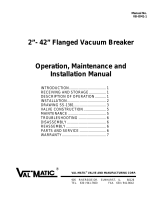
VAL-MATIC'S 1/2"-3" VACUUM BREAKER
OPERATION, MAINTENANCE AND INSTALLATION
FIGURE 1. 1/2"-3" VACUUM BREAKER
CAUTION: This valve is not intended
for fuel service or fluids
containing suspended
solids.
DESCRIPTION OF OPERATION
The Vacuum Breaker is designed to prevent
vacuum conditions from occurring in pipes or
tanks. After a power failure or rapid draining of
the system, a vacuum condition often occurs in
a pipe or tank. The pressure difference between
the inside vacuum and outside air will cause a
downward force on the float. At vacuum
pressures greater than –0.25 psig, the float will
compress the spring and move downward
allowing free flow of outside air into the pipe or
tank to eliminate the vacuum.
When positive pressure is restored in the pipe or
tank, the vacuum breaker will automatically
close and seal tightly against the resilient seat.
Optional valves can be piped to the vacuum
breaker to vent trapped air in the pipeline if
needed.
The valve may be supplied with an optional
threaded hood for insertion into the top of the
valve. The only moving parts in the valve are the
float and the spring. The float guide controls the
movement of the float and assures that the float
contacts the seat evenly.
1

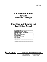
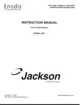
ITEM DESCRIPTION MATERIAL
1 Body Cast Iron
2 Cover Cast Iron
3 Baffle Ductile Iron
4 Seat* Buna-N
5 Float* Stainless Steel
6 Gasket* Non-Asbestos
7 Cover Bolt Alloy Steel
8 Retaining Screw* Stainless Steel
9 Guide Bushing* Stainless Steel
14 Pipe Plug Iron
20 Guide Shaft* Stainless Steel
21 Spring* Stainless Steel
*RECOMMENDED SPARE PART
INSTALLATION
The installation of the Vacuum Breaker is
important for its proper operation. The seat end
must be oriented upward. The device should be
installed on top of horizontal lines or tanks and
equipped with a full-ported isolation valve. If
installed in a vault, adequate ventilation is
needed to supply air to the vacuum breaker.
It leakage occurs at the pipe connection, torque
valve tighter or reapply pipe dope to threaded
joint.
VALVE CONSTRUCTION
The Vacuum Breaker body and cover are cast
iron. All internal components are stainless steel
with the exception of the valve seat which is
resilient. The float (5) and float guide shaft (20)
are the only moving parts assuring long life with
minimal maintenance. The general details of
construction are illustrated in Figure 2. The body
(1) is threaded for connection to the pipeline. The
seat (4) is retained in the cast cover (2). The seat
(4) is retained by a baffle (3).
FIGURE 2. 1/2"-3" VACUUM BREAKER
TABLE 1. 1/2"-3" Vacuum Breaker Parts List
MAINTENANCE
The Vacuum Breaker requires no scheduled
lubrication or maintenance.
TROUBLESHOOTING
Several problems and solutions are presented
below to assist you in troubleshooting the
vacuum breaker assembly in an efficient
manner.
•Leakage at Bottom Connection: Tighten
threaded connection. If leak persists, remove
device and seal threads with Teflon sealant.
•Leakage at Cover: Tighten bolts, replace
gasket.
•Device Leaks when Closed: Inspect seat for
damage and replace.
DISASSEMBLY
The device can be disassembled without
removing it from the pipeline. Or for
convenience, the device can be removed from
the line. All work on the valve should be
performed by a skilled mechanic with proper
tools.
WARNING: The line must be drained
before removing the cover
or pressure may be
released causing bodily
harm.
2

SIZE TORQUE (FT-LBS)
5/16" 10
3/8" 24
1/2" 59
5/8" 117
DISASSEMBLY (continued)
1. Close inlet shut-off valve. Open drain valve
or remove drain plug. Remove the cover
bolts (7) on the top cover.
2. Pry cover (2) loose and lift off body (1).
3. Remove retainer bolts (8) and inspect seat
for cracks in rubber or wear in sealing
surface.
TABLE 2. VALVE COVER BOLT TORQUES
4. Turn guide bushing (9) to remove it from the
cast baffle (3). PARTS AND SERVICE
Parts and service are available from your local
representative or the factory. Make note of the
valve Size, Series No, and Serial No. located on
the valve nameplate and contact:
5. Clean and inspect parts. Replace worn parts
as necessary.
Val-Matic Valve and Mfg. Corp.
RE-ASSEMBLY 905 Riverside Drive
All parts must be cleaned and gasket surfaces
should be cleaned with a stiff wire brush in the
direction of the serrations or machine marks.
Worn parts, gaskets and seals should be
replaced during reassembly.
Elmhurst, IL 60126
PH: 630/941-7600
FAX: 630/941-8042
A sales representative will quote prices for parts
or arrange for service as needed.
1. Apply Loctite to guide bushing threads (9)
and thread bushing into baffle (3). Insert float
shaft into float (5).
2. Lay seat (4) over inverted cover with flat
surface directed toward cover.
3. Install float assembly and spring (21) and
baffle over seat and secure with retaining
bolts (8) at 10 ft-lbs.
4. Lay cover gasket (6) and cover (2) over bolt
holes in body (1).
5. Insert lubricated bolts (7) and tighten to the
torques listed in Table 2.
3

LIMITED WARRANTY
A
ll products are warranted to be free of defects in material and workmanship for a period of one year from the date of
shipment, subject to the limitations below.
If the purchaser believes a product is defective, the purchaser shall: (a) Notify the manufacturer, state the alleged defec
t
and request permission to return the product; (b) if permission is given, return the product with transportation prepaid. I
f
the product is accepted for return and found to be defective, the manufacturer will, at his discretion, either repair or replace
the product, f.o.b. factory, within 60 days of receipt, or refund the purchase price. Other than to repair, replace or refund
as described above, purchaser agrees that manufacturer shall not be liable for any loss, costs, expenses or damages o
f
any kind arising out of the product, its use, installation or replacement, labeling, instructions, information or technical data
of any kind, description of product use, sample or model, warnings or lack of any of the foregoing. NO OTHE
R
WARRANTIES, WRITTEN OR ORAL, EXPRESS OR IMPLIED, INCLUDING THE WARRANTIES OF FITNESS FOR
A
PARTICULAR PURPOSE AND MERCHANTABILITY, ARE MADE OR AUTHORIZED. NO AFFIRMATION OF FACT,
PROMISE, DESCRIPTION OF PRODUCT OF USE OR SAMPLE OR MODEL SHALL CREATE ANY WARRANTY FROM
MANUFACTURER, UNLESS SIGNED BY THE PRESIDENT OF THE MANUFACTURER. These products are no
t
manufactured
,
sold or intended for
p
ersonal
,
famil
y
or household
p
ur
p
oses.
VALVE AND MANUFACTURING CORP.
905 Riverside Dr. ● Elmhurst, IL 60126
Phone (630) 941-7600 ● Fax (630) 941-8042
www.valmatic.com
4
/