Page is loading ...

736V V-PLEX MODULE
Installation Guide
DESCRIPTION
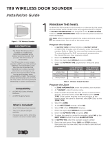
Figure1: 736V V-Plex Module
The736V V‑Plex® Module allows
technicians to replace Honeywell®
VISTA® FB Series panels with DMP
XR150/XR550Series panels without
requiring the replacement of serial
number addressable V‑Plex devices.
When connected to an
XR150/XR550Series panel,
themodule converts V‑Plex devices
to DMP LX‑Bus zones.
Each736V supports up to96V‑Plex
devices. To add more devices to a
system, connect a second module
to another LX‑Bus and second
polling loop circuit.
Compatibility
• XR150/XR550Series Panels with
Firmware Version 191 (7/2/19) or
Higher
• V‑Plex devices with serial
number addresses. For a list of
compatible V‑Plex devices, refer
to Compatibility.
What is Included?
• One736V V‑Plex Module
• One Model 330 Dual ‑Ended
4‑Wire Harness
• Hardware pack
1
FIND V-PLEX DEVICE SERIAL NUMBERS
Before removing the Honeywell VISTA control panel and cabinet,
you can retrieve a list of V‑Plex device serial numbers and names
from the panel with Honeywell’s Compass® remote programming
software. Printing V‑Plex device information will be helpful
when programming the devices into the panel and will reduce
programming time. Serial numbers are also printed on each V‑Plex
device.
If you don’t have access to the device serial numbers, refer to 736V
V‑Plex Advanced Settings Guide (LT‑1934) for information about
alternative programming.
MOUNT THE 736V
2
After replacing the Honeywell VISTA control panel and cabinet
with an XR150or XR550Series panel and DMP enclosure, mount
the module in the enclosure using the standard 3‑hole mounting
pattern. Refer to Figure2and Figure3as needed during
installation.
1. Hold the plastic standos against the inside of the
enclosure side wall.
2. Insert the included Phillips head screws from the outside of
the enclosure into the standos. Tighten the screws.
3. Carefully snap the module onto the standos.
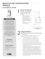
Keypad Ena.
Write Ena./
Clear
LX Bus
Connection
Polling Loop Terminals
Mounting Holes
LX
Figure2: 736V PCB Configuration
Figure3: Stando Installation

2 736V INSTALLATION GUIDE | DIGITAL MONITORING PRODUCTS
3
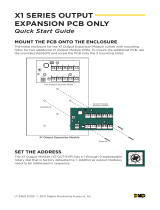
The736V requires wiring connections from the LX header and polling loop terminals. Refer to Figure4when
wiring the module.
Warning Cycling power to the panel or rebooting the736V with the jumper on both WriteEna/Clear pins
will delete any data saved in the 736V. Leaving V‑Plex devices disconnected from power for long periods of
time may also result in data loss. When the system is powered on, do not to touch the polling loop wires
together.
1. Use the Model3304‑wire harness to connect themodule LX header directly to a panel LX‑Bus header.
This connection allows the module to communicate with the panel and receive12VDC power.
2. Short the two V‑Plex polling loop wires by touching them together for approximately30seconds.
3. Connect the red wire from the polling loop to the positive module terminal. Connect the black wire from
the polling loop to the negative module terminal.
4. Remove both jumpers from Keypad Ena and Write Ena/Clear, then power up the panel.
Note: DMP XR150/XR550Series panels provide up to1.5Amps of auxiliary power. The total current of all
keypads, modules, and devices that are connected to modules cannot exceed1.5Amps. When performing
standby battery calculations, include the total current draw of all connected V‑Plex devices.
WIRE THE 736V
Keypad Ena.
Write Ena./
Clear
RED
BLACK
To Polling Loop
To LX-Bus
LX
Figure4: 736V Wiring Diagram

736V INSTALLATION GUIDE | DIGITAL MONITORING PRODUCTS 3
PROGRAM THE PANEL
Set the 736V Address
On XR550 panels, connect a 736V to any LX‑Bus. V‑Plex devices are addressed on one LX‑Bus per loop. On
XR150 panels, address 501 is reserved for the 736V.
Unused zones on an LX‑Bus connected to a 736V can be used for any non‑polling loop devices except access
control devices. See Table1for more information about device addresses and zones.
After completing each of the following steps, press CMD to advance to the next option.
1. Reset the panel. Enter (PROG) at the panel keypad and go to DEVICE SETUP.
2. At DEVICE NO, enter the device number of the LX‑Bus slot taken up by themodule.
3. If the LX‑Bus already has zones programmed, ZONES PROGRAMMED CONTINUE? NO YES displays. To
continue programming, select YES.
Note: Selecting YES at ZONES PROGRAMMED CONTINUE? does not overwrite existing
programming.
4. At DEVICE NAME, enter a name for the module.
5. (XR550 only) At DEVICE TYPE, select VPX.
XRXR XR Only
Device Zones Device Zones Device Zones Device Zones Device Zones
501 500‑595 601 600‑695 701 700‑795 801 800‑895 901 900‑995
Table1: Device Addresses and V-Plex Zone Numbers
Note: Zones 96‑99 on any LX‑Bus that is connected to a 736V are diagnostic zones. For more information
refer to the 736V V‑Plex Advanced Settings Guide (LT‑1934).
Program V‑Plex Zones
After completing each of the following steps, press CMD to advance to the next option.
1. Go to ZONE INFORMATION.
2. At ZONE NO, enter the device zone that corresponds to the LX‑Bus.
3. At *UNUSED*, enter the zone name.
4. At ZONE TYPE, select the zone type.
5. At the Area Assignment section, select the area.
6. At the NEXT ZN? prompt, select NO.
7. At the DMP WLS? NO YES prompt, select NO.
8. At VPLEX DEVICE SERIAL, enter A followed by the7‑digit serial number.
9. At the NEXT ZN? prompt, select YES.
10. Repeat steps2through10for the remaining devices.
11. To save panel programming, go to STOP and press CMD.
Turn on Outputs
Smoke and PIR motion detector zones require that the output corresponding to the programmed zone are
turned on to report the status correctly. For example, if you have a PIR on zone 503, output 503 will need to
be toggled on for the zone to report correctly.
Go to the User Menu, enter a valid code that has output authority. Go to OUTPUTS ON/OFF? and enter the
output number that corresponds to the zone. Select top row key 3 to toggle the output ON.
Note: Do not program smoke or PIR motion detector zones as outputs in OUTPUT INFO.
4

Designed, engineered, and
manufactured in Springfield, MO
using U. S. and global components.
LT‑1910 19125
INTRUSION • FIRE • ACCESS • NETWORKS
2500North Partnership Boulevard
Springfield, Missouri65803‑8877
800.641.4282 | DMP.com
736V V‑PLEX MODULE
Specifications
Primary Power 12VDC
Current Draw 45mA
Dimensions 2”H X3.5”W X0.5D
Accessories
Model 330 Dual‑Ended 4‑Wire Harness
Compatibility
XR150/XR550 Series Panels with Firmware Version 191
(7/2/19) or higher
V‑Plex Devices
DT7500SN V‑Plex DUAL TEC Motion Sensor
5193SD/5193SDT One Piece Photoelectric Smoke Detector
4959SN Addressable Overhead Door Contact
4193SN/4293SN Micro‑miniature V‑Plex Adapter
IS2500SN V‑Plex PIR Motion Sensor
269SN V‑Plex Holdup Switch
4939SN Addressable Surface Mount Contact
4190SN Two Zone Remote Point Module
FG1625SN FlexGuard®
419SN‑WH Recessed Door Contact
4101SN Relay Module
VPLEX‑VSI V‑Plex Short Isolator
4208U Universal Eight Zone Remote Point Module
ADDITIONAL INFORMATION
Diagnostic LEDs
Themodule has two onboard LEDs. The green LED indicates connection to the LX‑Bus and should flash once every two
seconds. The yellow LED indicates that polling loop devices are communicating with the module.
Reboot the736V
Before rebooting the module, remove the jumper from the WriteEna/Clear pins. To reboot, turn the last LX‑Bus output
o, then back on. For example, if themodule is connected to LX500, turn output599on then o.
Reuse a736V V‑Plex Module
Before reusing a736V, disconnect all zones. Delete all data in the module by placing the jumper across both
WriteEna/Clear pins and powering up the panel.
5
Perform a Burglary Zone Walk Test to confirm that all of the devices are properly configured and
communicating with the panel.
1. Reset the panel.
2. At a keypad, enter (WALK) and select BG.
3. Trip each zone on the system for 1 to 2 seconds. The keypad will annunciate each time a zone is tripped
and display the number of zones successfully tripped.
4. Press the fourth select area or key to end the Walk Test.
TEST THE 736V
/