Page is loading ...

Installation Instructions
POINT I/O 24V DC 4-channel Discrete
Input Module with Diagnostics
Catalog Number 1734-IB4D
Table of Contents
Topic Page
Important User Information 2
Environment and Enclosure 3
Prevent Electrostatic Discharge 4
About the Module 6
Before You Begin 7
Understand Short Circuit Detection 7
Understand Open-wire Detection 8
Install the Mounting Base 9
Install the Module 10
Install the Removable Terminal Block 13
Wire the Module 14
Configure the Module 16
Interpret the Indicators 18
Remove a Mounting Base 20
Specifications 21

2 POINT I/O 24V DC 4-channel Discrete Input Module with Diagnostics
Publication 1734-IN029B-EN-E - July 2018
Important User Information
Solid state equipment has operational characteristics differing from those of electromechanical
equipment. Safety Guidelines for the Application, Installation and Maintenance of Solid State Controls
(Publication SGI-1.1
available from your local Rockwell Automation sales office or online at
http://literature.rockwellautomation.com
) describes some important differences between solid state
equipment and hard-wired electromechanical devices. Because of this difference, and also because of the
wide variety of uses for solid state equipment, all persons responsible for applying this equipment must
satisfy themselves that each intended application of this equipment is acceptable.
In no event will Rockwell Automation, Inc. be responsible or liable for indirect or consequential damages
resulting from the use or application of this equipment.
The examples and diagrams in this manual are included solely for illustrative purposes. Because of the
many variables and requirements associated with any particular installation, Rockwell Automation, Inc.
cannot assume responsibility or liability for actual use based on the examples and diagrams.
No patent liability is assumed by Rockwell Automation, Inc. with respect to use of information, circuits,
equipment, or software described in this manual.
Reproduction of the contents of this manual, in whole or in part, without written permission of Rockwell
Automation, Inc., is prohibited.
Throughout this manual, when necessary, we use notes to make you aware of safety considerations.
WARNING: Identifies information about practices or circumstances that can cause an
explosion in a hazardous environment, which may lead to personal injury or death,
property damage, or economic loss.
ATTENTION: Identifies information about practices or circumstances that can lead to
personal injury or death, property damage, or economic loss. Attentions help you
identify a hazard, avoid a hazard, and recognize the consequences.
SHOCK HAZARD: Labels may be on or inside the equipment (for example, drive or
motor) to alert people that dangerous voltage may be present.
BURN HAZARD: Labels may be on or inside the equipment (for example, drive or
motor) to alert people that surfaces may reach dangerous temperatures.
IMPORTANT Identifies information that is critical for successful application and understanding of
the product.

POINT I/O 24V DC 4-channel Discrete Input Module with Diagnostics 3
Publication 1734-IN029B-EN-E - July 2018
Environment and Enclosure
ATTENTION: This equipment is intended for use in a Pollution Degree 2
industrial environment, in overvoltage Category II applications (as defined in
EN/IEC 60664-1), at altitudes up to 2000 m (6562 ft) without derating.
This equipment is not intended for use in residential environments and may not
provide adequate protection to radio communication services in such environments.
This equipment is supplied as open-type equipment for indoor use. It must be
mounted within an enclosure that is suitably designed for those specific
environmental conditions that will be present and appropriately designed to
prevent personal injury resulting from accessibility to live parts. The enclosure
must have suitable flame-retardant properties to prevent or minimize the spread
of flame, complying with a flame spread rating of 5VA or be approved for the
application if nonmetallic. The interior of the enclosure must be accessible only
by the use of a tool. Subsequent sections of this publication may contain more
information regarding specific enclosure type ratings that are required to
comply with certain product safety certifications.
In addition to this publication, see the following:
• Industrial Automation Wiring and Grounding Guidelines, publication
1770-4.1
, for more installation requirements.
• NEMA Standard 250 and EN/IEC 60529, as applicable, for explanations of
the degrees of protection provided by enclosures.
ATTENTION:
Read this document and the documents listed in the Additional
Resources section about installation, configuration, and operation of this
equipment before you install, configure, operate, or maintain this product. Users
are required to familiarize themselves with installation and wiring instructions
in addition to requirements of all applicable codes, laws, and standards.
Installation, adjustments, putting into service, use, assembly, disassembly, and
maintenance are required to be carried out by suitably trained personnel in
accordance with applicable code of practice. In case of malfunction or damage,
no attempts at repair should be made. The module should be returned to the
manufacturer for repair. Do not dismantle the module.

4 POINT I/O 24V DC 4-channel Discrete Input Module with Diagnostics
Publication 1734-IN029B-EN-E - July 2018
Prevent Electrostatic Discharge
Special Conditions for Safe Use
ATTENTION: This equipment is sensitive to electrostatic discharge, which can
cause internal damage and affect normal operation.
Follow these guidelines when you handle this equipment:
• Touch a grounded object to discharge potential static.
• Wear an approved grounding wriststrap.
• Do not touch connectors or pins on component boards.
• Do not touch circuit components inside the equipment.
• Use a static-safe workstation, if available.
• Store the equipment in appropriate static-safe packaging when not in use.
ATTENTION:
• This product is grounded through the DIN rail to chassis ground. Use zinc
plated chromate-passivated steel DIN rail to assure proper grounding. The
use of other DIN rail materials (for example, aluminum or plastic) that can
corrode, oxidize, or are poor conductors, can result in improper or
intermittent grounding. Secure DIN rail to mounting surface approximately
every 200 mm (7.8 in.) and use end-anchors appropriately. Be sure to
ground the DIN rail properly. Refer to Industrial Automation Wiring and
Grounding Guidelines, publication 1770-4.1
, for more information.
• Do not remove or replace an Adapter Module while power is applied.
Interruption of the backplane can result in unintentional operation or
machine motion.
• Do not discard the end cap. Use this end cap to cover the exposed
interconnections on the last mounting base on the DIN rail. Failure to do
so could result in equipment damage or injury from electric shock.
• If this equipment is used in a manner not specified by the manufacturer,
the protection provided by the equipment may be impaired.

POINT I/O 24V DC 4-channel Discrete Input Module with Diagnostics 5
Publication 1734-IN029B-EN-E - July 2018
Electrical Safety Considerations
ATTENTION: This equipment is certified for use only within the surrounding
air temperature range of 0…55 °C (32…131 °F). The equipment must not be
used outside of this range.
At the end of its life, this equipment should be collected separately from any
unsorted municipal waste.

6 POINT I/O 24V DC 4-channel Discrete Input Module with Diagnostics
Publication 1734-IN029B-EN-E - July 2018
About the Module
This module is a 4-channel 24V DC input module with short circuit and
open-wire diagnostics.
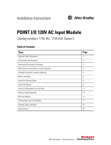
See the figures to familiarize yourself with major parts of the module, noting that the
wiring base assembly is one of the following, with the module not being compatible with
1734-TB3, 1734-TB3S, 1734-TOP3, and 1734-TOP3S bases:
• 1734-TB POINT I/O™ two-piece terminal base, which includes the 1734-RTB
removable terminal block
• 1734-TOP or 1734-TOPS POINT I/O one-piece terminal bass
POINT I/O Input Module with 1734-TB Base
Module
Status
Network
Status
NODE:
0
1
2
3
Removable
Terminal Block
(RTB)
Removable Terminal
Block (RTB) handle
Module locking
mechanism
Module wiring diagram
DIN Rail locking screw (orange)
Interlocking side pieces
Mechanical keying
(orange)
Mounting base
Slide-in writable label
Insertable I/O module
44328

POINT I/O 24V DC 4-channel Discrete Input Module with Diagnostics 7
Publication 1734-IN029B-EN-E - July 2018
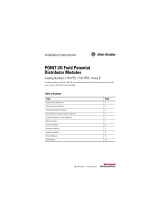
POINT I/O Input Module with 1734-TOP or 1734-TOPS Base
Before You Begin
The module supports remove and insert under power, auto-address, and auto-baud in
compliance with the POINTBus™ backplane. Each input is a sinking DC input with short
circuit and open-wire detection. The sensor source voltage is derived from the user
auxiliary power and used as I/O power.
Understand Short Circuit Detection
The sensor source voltage (SSV) for each input is protected against short circuits. For
currents above 200 mA, a fault signal is issued and the input LED indicator is illuminated
solid red. A thermally actuated smart-power device or PTC is used as the protection
means. On a per-input basis, the circuit and produced data automatically reset and SSV
energizes upon removal of the short circuit. An individual fault signal is issued for each
shorted SSV condition.
The shorted input LED indicator illuminates red to denote short circuit fault status.
See the section on interpreting LED indicators for related information.
44221
One-piece
terminal
base with
screw or
spring
clamp
Insertable
I/O module
Module locking
mechanism
Slide-in writable label
Interlocking
side pieces
DIN Rail locking
screw (orange)
Module wiring diagram
Mechanical
Keying (orange)
Handle

8 POINT I/O 24V DC 4-channel Discrete Input Module with Diagnostics
Publication 1734-IN029B-EN-E - July 2018
When the SSV is loaded to the maximum rated current of 50 mA, a voltage drop of as
much as 2.5V DC can exist between the user auxiliary power and the SSV connection. For
example, for a supply of 10V DC to a sensor with power derived from the SSV, a supply of
12.5V DC is needed at the auxiliary power connection.
Understand Open-wire Detection
Sensor source voltage (SSV) current for each input is monitored. Monitoring is
accomplished in the SSV leg to accommodate the largest number of sensors possible. For
currents below 0.5 mA, a fault signal is issued and the LED indicator of the input blinks
red. On a per-input basis, the circuit and produced data automatically reset upon removal
of the open-wire condition. See the information about interpreting LED indicators for
related information.
By using a configuration tool, you can disable the open-wire diagnostics on an input-point
basis to keep unused input indicators from turning red and signaling a fault when an input
is not in use. Enabling or disabling input-point level open-wire diagnostics is implemented
via the EDS file of the module, GSD file, or Logix profile and its firmware.
You can also disable all the open-wire diagnostics, using a single entry via the software user
interface. The default configuration has all four input channels' open-wire
indication enabled.
If a sensor with a dry contact output is used, wire one side of the contact to the SSV
terminal for the corresponding input. Wire the other side of the contact to the input.
Additionally, place a shunt resistor in parallel with the contact, at the sensor, to cause
greater than 0.5 mA to be drawn through the SSV terminal at all times.

POINT I/O 24V DC 4-channel Discrete Input Module with Diagnostics 9
Publication 1734-IN029B-EN-E - July 2018
Install the Mounting Base
To install the mounting base on the DIN rail, proceed as follows:
1. Position the mounting base vertically above the installed units, for example,
adapter, power supply, or existing module.
2. Slide the mounting base down so that the interlocking side pieces engage the
adjacent module or adapter.
3. Press firmly to seat the mounting base on the DIN rail until the mounting base
snaps into place.
31586
Slide the mounting base until the
interlocking side pieces engage the
adjacent module or adapter.

10 POINT I/O 24V DC 4-channel Discrete Input Module with Diagnostics
Publication 1734-IN029B-EN-E - July 2018
Install the Module
Install the module before or after base installation. Before installing the module into the
mounting base be sure of this.
• The mounting base is correctly keyed.
• The mounting base locking screw is positioned horizontally referenced to the base.
1734-TB Base
Be sure that the DIN
rail locking screw is in
the horizontal
44229
Turn the keyswitch
to align the number
with the notch.
Notch position 3 is
shown.

POINT I/O 24V DC 4-channel Discrete Input Module with Diagnostics 11
Publication 1734-IN029B-EN-E - July 2018
1734-TOP Base
To install the module, use this procedure:
1. Use a bladed screwdriver to rotate the keyswitch on the mounting base clockwise
until the number required for the type of module being installed aligns with the
notch in the base.
2. Be sure that the DIN rail locking screw is in the horizontal position, noting that
you cannot insert the module if the locking mechanism is unlocked.
3. Insert the module straight down into the mounting base and press to secure, until
the module locks into place.
Turn the keyswitch
to align the
number with the
notch.
Notch position 1 is
shown.
Be sure that the DIN
rail locking screw is in
the horizontal position.
44228

12 POINT I/O 24V DC 4-channel Discrete Input Module with Diagnostics
Publication 1734-IN029B-EN-E - July 2018
4. Insert the end opposite the handle into the base unit, noting this end has a curved
section that engages with the wiring base.
5. Rotate the terminal block into the wiring base until it locks itself in place.
6. Snap the RTB handle into place on the module, if an I/O module is installed
220VAC
Input
Module
Status
Network
Status
NODE:
0
1
Insert the module straight down into the
mounting base.
Hook the RTB end into
the mounting base end
and rotate until it locks
into place.
44011

POINT I/O 24V DC 4-channel Discrete Input Module with Diagnostics 13
Publication 1734-IN029B-EN-E - July 2018
Install the Removable Terminal Block
Read this for information if a removable terminal block (RTB) is supplied with your
wiring base assembly, noting that 1734-TOP and 1734-TOPS bases do not have an RTB.
To insert the RTB, proceed as follows. Note that if you pull up on the RTB handle to
remove the RTB, you can remove and replace the mounting base as necessary without
removing any of the wirings.
1. Insert the end opposite the handle into the base unit, noting that this end has a
curved section that engages with the wiring base.
2. Rotate the terminal block into the wiring base until it locks itself into place.
3. If an I/O module is installed, snap the RTB handle into place on the module.

14 POINT I/O 24V DC 4-channel Discrete Input Module with Diagnostics
Publication 1734-IN029B-EN-E - July 2018
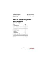
Wire the Module
See the figure and tables for information about how to wire the module.
1734-IB4D
41974
Module status
Network status
Input 0 SSV 0
Input 1 SSV 1
Input 2 SSV 2
Input 3 SSV 3
Status of input 0
Status of input 1
Status of input 2
Status of input 3
Note: Voltage and current are daisychained from either the adapter,
1734-FPD module, or 1734-EP24DC module.
Common connections for three-wire devices require an external wiring
connection. A 1734-CTM module can provide the common connection.

POINT I/O 24V DC 4-channel Discrete Input Module with Diagnostics 15
Publication 1734-IN029B-EN-E - July 2018
Wiring
POINT I/O Input Module
Channel Terminal Number
I/O Common Voltage
0 0 External
(1)
(1)
Common connections require an external connection, such as a 1734-CTM module.
1
12 3
24 5
36 7
Connect common on three-wire proximity switches.
10/28.8V DC is supplied through the internal power bus.
In 0
V 0
Sink Input
3
5
7
01
2
4
6
V=10/28.8V DC
If a common connection is required (three-wire devices), then a 1734-CTM
common terminal module can be required.
Prox
Prox
Prox
Prox
In 2
In 3
In 1 V 1
V 2
V 3
44226

16 POINT I/O 24V DC 4-channel Discrete Input Module with Diagnostics
Publication 1734-IN029B-EN-E - July 2018
Configure the Module
Read this section for information about how to communicate with your module.
I/O messages are sent to (consumed) and received from (produced) the POINT I/O
modules. These messages are mapped into the memory of the processor or scanner. This
POINT I/O input module produces 1 byte or 2 bytes of input data based on which
produced assembly is selected. The default setup is 2 bytes. It does not consume I/O data
(scanner Tx).
Default Data Map – Produced Assembly Instance 101
Message Size: 2 Bytes
76543210
Produce 0 (Rx) Fault 3 Fault 2 Fault 1 Fault 0 Input 3 Input 2 Input 1 Input 0
Produce 1 (Rx) SC 3 SC 2 SC 1 SC 0 OW 3 OW 2 OW 1 OW 0
Consume (Tx) No consumed data
Data Map – Produced Assembly Instance 23
Message Size: 1 Byte
76543210
Produce 0 (Rx) Fault 3 Fault 2 Fault 1 Fault 0 Input 3 Input 2 Input 1 Input 0
Consume (Tx) No consumed data
Where: Fault = open wire or short circuit
Default Data Map – Configuration Assembly Instance 103
Message Size: 18 Bytes
76543210
Consume 0 Input 0 off to on filter byte 0
Consume 1 Input 0 off to on filter byte 1
Consume 2 Input 0 on to off filter byte 0
Consume 3 Input 0 on to off filter byte 1

POINT I/O 24V DC 4-channel Discrete Input Module with Diagnostics 17
Publication 1734-IN029B-EN-E - July 2018
Consume 4 Input 1 off to on filter byte 0
Consume 5 Input 1 off to on filter byte 1
Consume 6 Input 1 on to off filter byte 0
Consume 7 Input 1 on to off filter byte 1
Consume 8 Input 2 off to on filter byte 0
Consume 9 Input 2 off to on filter byte 1
Consume 10 Input 2 on to off filter byte 0
Consume 11 Input 2 on to off filter byte 1
Consume 12 Input 3 off to on filter byte 0
Consume 13 Input 3 off to on filter byte 1
Consume 14 Input 3 on to off filter byte 0
Consume 15 Input 3 on to off filter byte 1
Consume 16
Autobaud
Disable
– Enable
OW3
Enable
OW2
Enable
OW1
Enable
OW0
Consume 17 Produced Assembly Instance
Produce (Tx) No produced data
Where: OW = open wire
Default Data Map – Configuration Assembly Instance 103
Message Size: 18 Bytes
76543210

18 POINT I/O 24V DC 4-channel Discrete Input Module with Diagnostics
Publication 1734-IN029B-EN-E - July 2018
Interpret the Indicators
See the figure and table that show how to interpret LED indicators.
1734-IB4D
Interpret LED Indicators Module Status
Indication Probable Cause Recommended Action
Module Status
Off No power applied to device. Apply power to device.
Green Device operating normally. None.
Flashing green Device needs commissioning due to
configuration missing, incomplete,
or incorrect.
Configure device properly.
Flashing red Recoverable fault. 1. Cycle power to device.
2. If condition persists, replace device.
Red Unrecoverable fault may require
device replacement.
Replace device.
Flashing red/green Device is in self-test. None.
Status of input 0
Status of input 1
Status of input 2
Status of input 3
Module status
Network status
44217

POINT I/O 24V DC 4-channel Discrete Input Module with Diagnostics 19
Publication 1734-IN029B-EN-E - July 2018
Interpret LED Indicators Network Status
Indication Probable Cause Recommended Action
Network Status
Off Device is not online.
– Device has not completed
dup_MAC_id test.
– Device not powered – check
Module Status indicator
Apply power to device, wait for
dup_MAC_id to complete, and correct,
as needed.
Flashing green Device is online but has no
connections in the established state.
None – device is in Idle or Program mode.
Green Device online and has connections
in the established state.
None.
Flashing red One or more I/O connections in
timed-out state.
Check for I/O module failure, and
correct, as needed.
Red Critical link failure – failed
communication device. Device
detected error that prevents it
communicating on the network.
Verify that adapter and terminal bases
are properly installed, and reinstall,
as needed.
Flashing red/green Communication faulted device – the
device has detected a network
access error and is in
communication faulted state.
Device has received and accepted
an Identify Communication Faulted
Request – long protocol message.
Verify that adapter is properly installed,
and reinstall, as needed.
Interpret LED Indicators I/O Status
Indication Probable Cause Recommended Action
I/O Status
Off Input is in the off state. None.
Yellow Input is in the on state. None.
Red Short circuit detected. Check I/O wiring or terminal base.
Flashing red Open wire detected. Check I/O wiring or terminal base.

20 POINT I/O 24V DC 4-channel Discrete Input Module with Diagnostics
Publication 1734-IN029B-EN-E - July 2018
Remove a Mounting Base
To remove a mounting base, you must first remove any installed module and the module
that is installed in the base to the right.
1. For a module with a two-piece terminal base, use these steps; otherwise, use
step 2
.
− Remove the removable terminal block (RTB), if wired.
− Unlatch the RTB handle on the I/O module.
− Pull on the RTB handle to remove the RTB.
2. Press the module lock on the top of the module.
3. Pull on the I/O module to remove from the base.
4. Repeat steps 1, 2, 3, and 4 for the module to the right.
5. Lift straight up to remove.
/