Page is loading ...

Bulletin 1609 Uninterruptible Power Supply
Catalog Numbers 1609-D and 1609-B
User Manual

Important User Information
Solid-state equipment has operational characteristics differing from those of electromechanical equipment. Safety
Guidelines for the Application, Installation and Maintenance of Solid State Controls (publication
SGI-1.1 available from
your local Rockwell Automation® sales office or online at
http://www.rockwellautomation.com/literature/) describes some
important differences between solid-state equipment and hard-wired electromechanical devices. Because of this difference,
and also because of the wide variety of uses for solid-state equipment, all persons responsible for applying this equipment
must satisfy themselves that each intended application of this equipment is acceptable.
In no event will Rockwell Automation, Inc. be responsible or liable for indirect or consequential damages resulting from the
use or application of this equipment.
The examples and Figures in this manual are included solely for illustrative purposes. Because of the many variables and
requirements associated with any particular installation, Rockwell Automation, Inc. cannot assume responsibility or
liability for actual use based on the examples and Figures.
No patent liability is assumed by Rockwell Automation, Inc. with respect to use of information, circuits, equipment, or
software described in this manual.
Reproduction of the contents of this manual, in whole or in part, without written permission of Rockwell Automation,
Inc., is prohibited.
Throughout this manual, when necessary, we use notes to make you aware of safety considerations.
Allen-Bradley, Rockwell Software, Rockwell Automation, and TechConnect are trademarks of Rockwell Automation, Inc.
Trademarks not belonging to Rockwell Automation are property of their respective companies.
WARNING: Identifies information about practices or circumstances that can cause an explosion in a hazardous environment,
which may lead to personal injury or death, property damage, or economic loss.
ATTENTION: Identifies information about practices or circumstances that can lead to personal injury or death, property
damage, or economic loss. Attentions help you identify a hazard, avoid a hazard, and recognize the consequence.
SHOCK HAZARD: Labels may be on or inside the equipment, for example, a drive or motor, to alert people that dangerous
voltage may be present.
BURN HAZARD: Labels may be on or inside the equipment, for example, a drive or motor, to alert people that surfaces may
reach dangerous temperatures.
IMPORTANT
Identifies information that is critical for successful application and understanding of the product.
WARNING: This is a category C2 UPS product. In a residential environment, this product may cause radio interference, in which
case the user may be required to take additional measures.

Rockwell Automation Publication 1609-UM009A-EN-P - January 2013 3
Preface
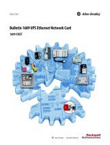
Additional Resources
These documents contain additional information concerning related products
from Rockwell Automation
You can view or download publications at
http:/www.rockwellautomation.com/literature/. To order paper copies of
technical documentation, contact your local Allen-Bradley distributor or
Rockwell Automation sales representative.
Resource Description
Industrial Automation Wiring and Grounding Guidelines,
publication
1770-4.1
Provides general guidelines for installing a Rockwell
Automation industrial system.
Product Certifications website,
http://www.ab.com Provides declarations of conformity, certificates, and
other certification details.
Publication Number:
1609-UM007_-EN-P
Bulletin 1609 UPS Management Software
User Manual
Publication Number:
1609-UM008_-EN-P
Network Management Card - Cat. No. 1609-ENET
User Manual
Publication Number:
1609-IN012_-EN-P
Bulletin 1609-D
Installation Instructions
Publication Number:
1609-IN013_-EN-P
Bulletin 1609-B
Installation Instructions
Publication Number:
1609-IN014_-EN-P
Surge Protective Device (Cat. No. 1609-SPD)
Installation Instructions
Publication Number:
1609-IN015_-EN-P
Network Management Card (Cat. No. 1609-ENET)
Installation Instructions

4 Rockwell Automation Publication 1609-UM009A-EN-P - January 2013
Preface
Notes:

Rockwell Automation Publication 1609-UM009A-EN-P - January 2013 5
Table of Contents
Bul. 1609-D Installation Instructions
Battery Wiring and Installation . . . . . . . . . . . . . . . . . . . . . . . . . . . . . . . . . . . . . 7
Mount the UPS . . . . . . . . . . . . . . . . . . . . . . . . . . . . . . . . . . . . . . . . . . . . . . . . . . . 8
Hardwire UPS . . . . . . . . . . . . . . . . . . . . . . . . . . . . . . . . . . . . . . . . . . . . . . . . . . . . 9
Selection of Cables . . . . . . . . . . . . . . . . . . . . . . . . . . . . . . . . . . . . . . . . . . . . . . . . . 9
Connect Power and Equipment to the UPS . . . . . . . . . . . . . . . . . . . . . . . . . 10
Bul. 1609-D Block Figure . . . . . . . . . . . . . . . . . . . . . . . . . . . . . . . . . . . . . . . . . 10
Bul. 1609-B Installation Instructions
Battery Wiring and Installation . . . . . . . . . . . . . . . . . . . . . . . . . . . . . . . . . . . . 11
Mount the UPS . . . . . . . . . . . . . . . . . . . . . . . . . . . . . . . . . . . . . . . . . . . . . . . . . . 13
Hardwire UPS . . . . . . . . . . . . . . . . . . . . . . . . . . . . . . . . . . . . . . . . . . . . . . . . . . . 13
Selection of Cables . . . . . . . . . . . . . . . . . . . . . . . . . . . . . . . . . . . . . . . . . . . . . . . . 13
Connect Power and Equipment to the UPS . . . . . . . . . . . . . . . . . . . . . . . . . 14
1609-B Block Figure . . . . . . . . . . . . . . . . . . . . . . . . . . . . . . . . . . . . . . . . . . . . . . 14
Bul. 1609-EXBAT Installation
Instructions
Battery Wiring and Installation . . . . . . . . . . . . . . . . . . . . . . . . . . . . . . . . . . . . 15
Mount the 1609-EXBAT. . . . . . . . . . . . . . . . . . . . . . . . . . . . . . . . . . . . . . . . . .17
Selection of Cables . . . . . . . . . . . . . . . . . . . . . . . . . . . . . . . . . . . . . . . . . . . . . . . . 18
Connect the 1609-EXBAT to the UPS . . . . . . . . . . . . . . . . . . . . . . . . . . . . . 18
General Information 1609-D and
1609-B
Recommended Battery for use with the UPS . . . . . . . . . . . . . . . . . . . . . . . . 19
Dry I/O Contacts . . . . . . . . . . . . . . . . . . . . . . . . . . . . . . . . . . . . . . . . . . . . . . . . 19
USB Communication Port . . . . . . . . . . . . . . . . . . . . . . . . . . . . . . . . . . . . . . . . 19
Manual or Remote Enable/Disable of UPS Output Selection . . . . . . . . . 20
Manual Enable/Disable/Self-test . . . . . . . . . . . . . . . . . . . . . . . . . . . . . . . . . . . 20
Remote Enable/Disable. . . . . . . . . . . . . . . . . . . . . . . . . . . . . . . . . . . . . . . . . . . . 20
Display LED Indicators. . . . . . . . . . . . . . . . . . . . . . . . . . . . . . . . . . . . . . . . . . . . 21
Troubleshooting
UPS LED Fault Indicators . . . . . . . . . . . . . . . . . . . . . . . . . . . . . . . . . . . . . . . . . 23
Output Short Circuit . . . . . . . . . . . . . . . . . . . . . . . . . . . . . . . . . . . . . . . . . 23
Output Overload . . . . . . . . . . . . . . . . . . . . . . . . . . . . . . . . . . . . . . . . . . . . . 23
Over Temperature from the Heatsink . . . . . . . . . . . . . . . . . . . . . . . . . . 23
Over Ambient Temperature . . . . . . . . . . . . . . . . . . . . . . . . . . . . . . . . . . . 23
Over Voltage from The DC/DC Converter of Inverter . . . . . . . . . . 23
Over Voltage from The Inverter . . . . . . . . . . . . . . . . . . . . . . . . . . . . . . . . 23
Under Voltage from The Inverter . . . . . . . . . . . . . . . . . . . . . . . . . . . . . . 23
Over Voltage from the Output . . . . . . . . . . . . . . . . . . . . . . . . . . . . . . . . . 24
Under Voltage from the Output . . . . . . . . . . . . . . . . . . . . . . . . . . . . . . . . 24
Fan Failure . . . . . . . . . . . . . . . . . . . . . . . . . . . . . . . . . . . . . . . . . . . . . . . . . . . 24
Charger Failure . . . . . . . . . . . . . . . . . . . . . . . . . . . . . . . . . . . . . . . . . . . . . . .24
TMOV Failure . . . . . . . . . . . . . . . . . . . . . . . . . . . . . . . . . . . . . . . . . . . . . . .24
Missing Battery . . . . . . . . . . . . . . . . . . . . . . . . . . . . . . . . . . . . . . . . . . . . . . . 24
Replace Batteries . . . . . . . . . . . . . . . . . . . . . . . . . . . . . . . . . . . . . . . . . . . . . . 24

6 Rockwell Automation Publication 1609-UM009A-EN-P - January 2013
Table of Contents
Troubleshooting (continued)
UPS Management Software Troubleshooting. . . . . . . . . . . . . . . . . . . . . . . .25
UPS Network Managemenr Card Troubleshooting . . . . . . . . . . . . . . . . . .26
Specifications
Bul. 1609-D Specifications . . . . . . . . . . . . . . . . . . . . . . . . . . . . . . . . . . . . . . . . .27
Bul. 1609-B Specifications . . . . . . . . . . . . . . . . . . . . . . . . . . . . . . . . . . . . . . . . .28
Dimensions
Bul. 1609-D Dimensions. . . . . . . . . . . . . . . . . . . . . . . . . . . . . . . . . . . . . . . . . . .29
Bul. 1609-B Dimensions . . . . . . . . . . . . . . . . . . . . . . . . . . . . . . . . . . . . . . . . . . .29
Bul. 1609-EXBAT Dimensions. . . . . . . . . . . . . . . . . . . . . . . . . . . . . . . . . . . . .29
Bul. 1609-BRK Dimensions . . . . . . . . . . . . . . . . . . . . . . . . . . . . . . . . . . . . . . . .30
Service Instructions
Service Instructions. . . . . . . . . . . . . . . . . . . . . . . . . . . . . . . . . . . . . . . . . . . . . . . .30

Rockwell Automation Publication 1609-UM009A-EN-P - January 2013 7
-Bulletin 1609-D Installation Instructions
Battery Wiring and
Installation
1. To access the battery compartment remove the three screws and the
battery door.
2. Remove the battery container, jumpers, and wire harness from the battery
compartment. Place the battery container and batteries onto a flat surface.
Use the provided jumper wires to connect the batteries in series. Connect
the positive terminal (red) of the battery to the negative terminal (black)
of another battery. See photo below for details.
3. Connect the red wire of the harness to the positive terminal (top red) and
the black wire of the harness to the negative terminal (bottom black). See
photo below for details.
ATTENTION: Do not service the 1609-SPD without disconnecting the power
sources due to electric shock hazard for risk of severe injury or death.

8 Rockwell Automation Publication 1609-UM009A-EN-P - January 2013
Bulletin 1609 UPS
Battery Wiring and
Installation (cont.)
4. Fold the battery container and seal it with tape.
5. To connect the batteries to the UPS, insert the batteries into the battery
compartment, open the white connector retainer and connect the two
cables together as shown in the photo below.
6. To complete the battery installation, close the white connector
retainer and reattach the battery door with the three screws
(torque of 8.7+/-1.7 lb-in).
Mount the UPS
The UPS-D is designed to mount on the back of the panel or to the floor of the
enclosure. The UPS mounts to a bracket assembly (1609-BRK) that allows it
to mount to either the panel or floor (see Figure 1 below).
Figure 1 - Mounting the UPS

Rockwell Automation Publication 1609-UM009A-EN-P - January 2013 9
Bulletin 1609 UPS
Hardwire UPS
Wiring of the UPS should be performed by a qualified electrician using the
appropriate wire gauges.
Selection of Cables
Table 1 - AC Main Input/Output Wiring for UPS:
Table 2 - DC Input / Output Wiring for External Battery Cabinet:
Item Specification
Wire Size 14 AWG
Minimum temperature 75 °C
Wire conductor material Copper only
Tightening torque for terminals 4.4 lb-in.
Item Specification
Wire Size 10 AWG
Minimum temperature 75 °C
Wire conductor material Copper only
Tightening torque for terminals 12 lb-in.
WARNING: To reduce the risk of fire, connect only to a circuit with 20 amperes
maximum branch circuit overcurrent protection in accordance with the National
Electric Code, ANSI/NFPA 70.
A disconnect switch shall be provided by others for AC output circuit.
To reduce the risk of fire, connect only to a circuit with branch circuit overcurrent
protection for 20 amperes rating in accordance with the National Electric Code,
ANSI/NFPA 70.

10 Rockwell Automation Publication 1609-UM009A-EN-P - January 2013
Bulletin 1609 UPS
Connect Power and
Equipment to the UPS
1. Connect the appropriate input power to the UPS's input (Line, Neutral
and Ground) terminals (see Figure 2).
2. Connect the specified equipment to the UPS's output (Line, Neutral and
Ground) terminals (see Figure 2).
Figure 2 - System Wiring
3. Connect any additional optional accessories (1609-ENET card).
1609-D Block Figure
WARNING: This UPS features Surge Protection Device (SPD) is located
on the left front of the unit. Disconnect all power sources before servicing
due to Electric Shock Hazard for risk of severe injury or death.
L
E
N
L
E
AC
Input
AC
Output
Backfeed
Relay
Inverter
Relay
+
-
AVR
AC to AC
AC to DC DC to DC DC to AC
Backfeed
Relay
Input
Filter
Breaker
N

Rockwell Automation Publication 1609-UM009A-EN-P - January 2013 11
Bulletin 1609 UPS
1609-B Installation Instructions
Battery Wiring
and Installation
Note: Batteries are not included with the 1609-B UPS
1. To access the battery compartment remove the three screws and the
battery door.
2. Remove the battery container, jumpers, and wire harness from the battery
compartment. Place the battery container and batteries onto a flat surface.
Use the provided jumper wires to connect the batteries in series. Connect
the positive terminal (red) of the battery to the negative terminal (black)
of another battery. Connect the red wire of the harness to the positive
terminal (top red) and the black wire of the harness to the negative
terminal (bottom black). See photo below for details.
3. Fold the battery container and seal it with tape.
ATTENTION: Disconnect the 1609-SPD before servicing, due to electric shock
hazard for risk of severe injury or death.

12 Rockwell Automation Publication 1609-UM009A-EN-P - January 2013
Bulletin 1609 UPS
Battery Wiring
and Installation (cont.)
4. To connect the batteries to the UPS, insert the batteries into the battery
compartment, open the white connector retainer and connect the two
cables together as shown in the photo below.
5. To complete the battery installation, close the white connector retainer
and reattach the battery door with the three screws (torque of 8.7+/-1.7 lb-in).

Rockwell Automation Publication 1609-UM009A-EN-P - January 2013 13
Bulletin 1609 UPS
Mount the UPS
The 1609-B UPS products are designed to mount to a heavy duty DIN-rail
(see Figure 3 below). The 1609-B UPS products are also designed with an
optional bracket assembly (Cat 1609-BRK) that allows it to mount to either
the panel or floor (see Figure 4 below).
Figure 3 - Standard DIN-Rail Mount
Figure 4 - Optional Panel or Floor Mount
Hardwire UPS
Wiring of the UPS should be performed by a qualified electrician using the
appropriate wire gauges.
Selection of Cables
Table 3 - AC Main Input / Output Wiring for UPS
Item Specification
Wire Size 14 AWG
Minimum Temperature 75 °C
Wire Conductor Material Copper only
Tightening Torque for Terminals 4.4 lb - in.
WARNING: To reduce the risk of fire, connect only to a circuit with 20 amperes
maximum branch circuit overcurrent protection in accordance with the National
Electric Code, ANSI/NFPA 70.
A disconnect switch shall be provided by others for AC output circuit.
To reduce the risk of fire, connect only to a circuit with branch circuit overcurrent
protection for 20 amperes rating in accordance with the National Electric Code,
ANSI/NFPA 70.

14 Rockwell Automation Publication 1609-UM009A-EN-P - January 2013
Bulletin 1609 UPS
Connect Power and
Equipment to the UPS
1. Connect the appropriate input power to the UPS's input (Line, Neutral
and Ground) terminals (see Figure 5).
2. Connect the specified equipment to the UPS's output (Line, Neutral and
Ground) terminals (see Figure 5).
Figure 5 - System Wiring
1609-B Block Figure
WARNING: This UPS features Surge Protective Device (SPD) located on the top
of the unit. Please disconnect all power sources before servicing due to Electric
Shock Hazard for risk of severe injury or death.
INPUT
LLNNGG
OUTPUT
AC Output
AC Input
L
E
N
L
E
AC
Input
AC
Output
Backfeed
Relay
Inverter
Relay
+
-
AC to DC (Charger) DC to DC DC to AC (Step Wave)
Backfeed
Relay
Input
Filter
N

Rockwell Automation Publication 1609-UM009A-EN-P - January 2013 15
Bulletin 1609 UPS
1609-EXBAT Installation Instructions
Battery Wiring
and Installation
Only use battery wires that have been provided with the 1609-EXBAT.
1. To access the battery compartment remove the six screws and the battery
door.
2. Remove the battery container, jumpers and wire harness from the battery
compartment. Place the battery container and batteries onto a flat surface.
Use the provided jumper wires to connect the batteries in series. Connect
the positive terminal (red) of the battery to the negative terminal (black)
of another battery. See photo below for details.
WARNING: A disconnect switch shall be provided by others for DC output
circuit. To reduce the risk of fire, connect only to a circuit with branch circuit
overcurrent protection for 35 amperes rating in accordance with the National
Electric Code, ANSI/NFPA 70.
Before connecting a battery pack to UPS, the emergent disconnecting device
shall be provided between the UPS and battery pack.

16 Rockwell Automation Publication 1609-UM009A-EN-P - January 2013
Bulletin 1609 UPS
Battery Wiring
and Installation (cont.)
3. Connect the shorter set of red and black wires of the harness to the top
terminals (red - to - red and black - to - black). Connect the longer set
of red and black wires of the harness to the bottom terminals (red - to - red
and black - to - black) and route the wires through the cut-out hole. See
photo below for details.
4. Fold the battery container and seal it with tape.
5. Insert the batteries into the battery compartment in the orientation as
shown in the photo below.
6. Open the white connector retainer and connect the two cables together
as shown in the photo below.

Rockwell Automation Publication 1609-UM009A-EN-P - January 2013 17
Bulletin 1609 UPS
Battery Wiring
and Installation (cont.)
7. To complete the battery installation, insert the surplus wire harness into
the free space, close the white connector retainer and reattach the battery
door with the six screws (torque of 8.7+/-1.7 lb-in).
Mount the 1609-EXBAT
The 1609-D UPS can be used with the External Battery Unit (1609-EXBAT).
The 1609-EXBAT unit is designed to mount to a heavy duty DIN-rail (see
Figure 6) or the optional mounting bracket assembly (1609-BRK) which
allows it to mount to either the panel or floor (see Figure 7).
Figure 6 - Heavy Duty DIN Rail Mount
Figure 7 - Panel or Floor Mount

18 Rockwell Automation Publication 1609-UM009A-EN-P - January 2013
Bulletin 1609 UPS
Selection of Cables
Table 4 - DC Input/Output Wiring for External Battery Cabinet
Connect 1609-EXBAT
to the UPS
To install the 1609-EXBAT unit with the 1609-D UPS, connect the three 10
AWG wires from the 1609-EXBAT terminals to the 1609-D UPS terminals
marked as ‘EXTERNAL BATT PACK (36V)’. (See Figure 8)
Dispose of used batteries according to the battery instructions.
Figure 8 - System Wiring
Item Specification
Wire Size 10 AWG
Minimum temperature 75 °C
Wire conductor material Copper only
Tightening torque for terminals 12 lb-in.

Rockwell Automation Publication 1609-UM009A-EN-P - January 2013 19
Bulletin 1609 UPS
General Information 1609-D
and 1609-B UPS Units
Recommended Battery
for Use with the UPS
and 1609-EXBAT
Rockwell Automation battery catalog numbers 1609-SBAT and 1609-HBAT
consist of the battery manufacturers listed below:
Not for use in a computer room as defined in the Standard for the Protection
of Electronic Computer/Data Processing Equipment, ANSI/NFPA 75.
Dry I/O Contacts
There is one Remote Enable/Disable Switch connection and 3 Dry I/O Contacts
available on the front of the UPS. Do not apply external power to the Remote
Enable/Disable Switch; however, the 3 sets of Dry Contacts require external
power supplies (Contacts Rating is 1A/24V DC). Each of the dry contacts is
used to provide a remote status indication of the UPS, as follows:
•1 and 2 On Battery Contact (NO)
•3 and 4 Low Battery Contact (NO)
•5 and 6 Fault (Indicates UPS has faulted see trouble shooting section)
•7 and 8 Remote On/O (Shorted (closed) for ON, Open for OFF)
USB Communication Port
The UPS supports a USB communication port for the end user
to connect with a computer. The user may monitor all the UPS
status through the USB port if the 1609 UPS Management
Software is installed in the computer. The software is stored
in the CD and can be found in the accessory bag.
Manufacturer MH Number Type Rating
B & B Battery (USA) MH19884 HRLS 5.5-12 12V DC, 2.75 Ah
BP 5-12 12V DC, 5.0 Ah
HR 5.5-12 12V DC, 2.75 Ah
SHR7-12 12V DC, 3.375 Ah
GS Yuasa International Ltd. MH12970 NPH5-12 12V DC, 5.0 Ah
Shenzhen Center Power Tech Co., Ltd. MH25860 CP1250 12V DC, 5.0 Ah
Shenzhen Ritar Power Co., Ltd. MH28539 RT1250 12V DC, 5.0 Ah
CSB Battery Co., Ltd. MH14533 HR1221W 12V DC, 5.25 Ah
Dispose of used batteries according to the battery instructions.
87654321

20 Rockwell Automation Publication 1609-UM009A-EN-P - January 2013
Bulletin 1609 UPS
Manual or Remote
Enable/Disable
of UPS Output Selection
The 1609 UPS output is designed to be manually or remotely enabled or
disabled. User is required to enable or disable the remote function switch
on the front panel.
• Selected 'DISABLE' for Manual Enable/Disable the UPS's Output.
• Selected 'ENABLE' for Remote Enable/Disable the UPS's Output.
Manual Enable/Disable/
Self-test
The Power Button on the front of the UPS is used to
manually enable or disable the output of the 1609-D UPS.
To enable the 1609-D UPS, press and hold the power
button until one beep is heard.
To disable the 1609-D UPS, press and hold the power button until three beeps
are heard, then release immediately (takes approximately 3 seconds).
To perform a self-test, press and hold the power button until two beeps are heard,
then release immediately. (The UPS must operate for at least 4 hours before
executing this function)
Remote Enable/Disable
An external switch connected to the Dry I/O terminals 7 and 8 is required
to remotely Enable or Disable the UPS output.
To enable the UPS, close the switch
that is connected to the Dry I/O
terminals 7 and 8.
To Disable the UPS, open the
switch that is connected to the
Dry I/O terminals 7 and 8.
REMOTE FUNCTION
ENABLEDISABLE
87654321
R
R
R
SW
24 Vdc
/