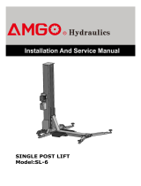
SPL-6

AMGO SPL-6 User manual

  • Hello! I've reviewed the user manual for the SPL-6 car lift. This document provides detailed step-by-step instructions for installation, including a comprehensive parts list and special instructions for exhibition setups. I'm ready to assist you with any questions you might have about the installation process or the lift's components.
  • What are the required installation space dimensions?
    What should be done before starting the installation?
    Do I need special parts for an exhibition?
STEPS OF INSTALLATION FOR SPL-6
1. Check and ensure the installation space is suitable for lift dimensions. (Length 4880mm*width 2820mm*height
2770mm)
2. Checks lifts model number and the parts before install. Take off the packaging on the machine and the packing rack.
Move aside the parts and check the parts according to the shipment parts list.
3. Optional partsOil tray/4pcs
4. Special parts needed for Exhibition(only for SEMA show
Platform 2pcs
Column
Supporting arm(Left
& Right)
Base
Lifting platform
Drive-in guideway plate
Power unit
Drive-in
Ramp
2 pcs
Tire Stop Plate
2pcs
Parts Box
Shipment list
Supporting arm pin
Safety device cover
Parts Box List
Parts Bag List
Supporting arm cover
Base Extension tube
5. Lay the base flat to the ground, confirm installation place according to the ground state.
6. Lay the column next to the base and connecting oil hose of cylinder.
7. Fix column to the base plate (be careful the column not slip when set the column upright ), install the bolts and make
the column vertical.
8. Install lifting platform
Note: make sure column do not press oil hose
.Connecting oil hose to the
fitting of cylinder, pull back
the carriage.
Pull out the
carriage
Install hex bolts: M20*50
with Lock Washer and
washer/10pcs)
Use shims to make the
column vertical
Level bar
Use forklift to raise the lifting platform to
match the mounting hole of carriage and
tighten the hex boltsM20*40 (with Lock
Washer and washer/8pcs)
9. Install Base Extension tube to strengthen the base (This only apply to SEMA show, since anchor bolts cannot be used
in SEMA show)
10. Install power unit, connect with 900 oil hose fitting and connect to power wire.
11. Install the oil hose clamp, press with the safety device spring, install the protective cover of safety device and add
the hydraulic oil.
12. Install Supporting arm (left and right) (Rise the lifting platform to first grade of safety lock to make it easier to
install)
Power wire
Oil hose and 900 oil
hose fitting
Base Extension tube:
4pcs
Install clamp
Hydraulic oil
Spring
Install the pin and Snap Ring (can
use a hammer to help if the pin is
too tight)
Supporting arm
Protective cover
13. Install the platform
14. Place the Drive-in guideway plate, place two wood beams below the front of the supporting arm, lower the lift to
the wood beam position, and then lower the lift until its convenient to install the limit slider.
①.
Put the platform on the supporting arm
and match the hole on the platform
②.
Install the screws beneath the platform
can
raise the machine higher to make it easier to
install
M12*16 screw with Lock Washer and washer
③.
Install the bolts on the platform
and tighten them. Hex bolt M12*35
with Lock Washer and washer, Nut
Place two wood beams below
the front of the supporting arm
Drive-in guideway plate
Limit slider
Socket bolt (with Lock
Washer, washer and nut):
M10*80mm
Hex bolt (With Lock Washer and
washer): M10*16mm
Limit slider mounting plate
15. Install the Drive-in Ramp and Tyre Stop plate, place the oil tray and supporting arm cover, and install the curtain.
Curtai
Drive-in Ramps
Tyre stop plate
Oil tray
Supporting arm
cover
/