Page is loading ...

INSTALLATION AND OPERATION MANUAL
MODELS: T11000-2OH-33
2 Post Automotive Lift
Maximum Lifting Capacity 11,000 lbs. / 4989 kg
Questions, problems, missing parts?
Before returning to your retailer, call our
customer service department at
1-888-448-6746 (1-888-44 TORIN),
8 a.m.- 5 p.m., PST, Monday-Friday.
Read carefully and understand all
ASSEMBLY AND OPERATION
INSTRUCTIONS before operating. Failure
to follow the safety rules and other basic
safety precautions may result in serious
personal injury.
INSTRUCTIONS TO READ THE MANUAL(S) THOROUGHLY BEFORE
INSTALLING, OPERATING, SERVICING, OR MAINTAINING THE LIFT.
PLEASE READ THE ENTIRE CONTENTS OF THIS MANUAL AND THE ANSI/ALI ALIS, SAFETY
REQUIREMENTS FOR INSTALLATION AND SERVICE FOR AUTOMITIVE LIFTS LITERATURE, PRIOR TO
INSTALLATION AND OPERATION. BY PROCEEDING WITH THE LIFT INSTALLATION AND OPERATION
YOU AGREE THAT YOU FULLY UNDERSTAND THE FULL CONTENTS OF THIS MANUAL. THIS MANUAL
MUST BE READ BY ALL USERS. FAILURE TO OPERATE THIS EQUIPMENT AS DIRECTED MAY CAUSE
INJURY OR DEATH.
IMPORTANT SAFETY INSTRUCTIONS
SAVE THESE INSTRUCTIONS
Keep this operation manual near the
machine at all times. Make sure all users
read this manual.
ORIGINAL INSTRUCTIONS IN ENGLISH LANGUAGE
RECEIVING
The shipment should be thoroughly inspected as
soon as it is received. The signed Bill of Lading is
acknowledgement by the shipping carrier as receipt
of this product as listed in your invoice as being in a
good condition of shipment. If any of these goods
listed on this Bill of Lading are missing or damaged,
do not accept goods until the shipping carrier makes
a notation on the freight bill of the missing or damaged
goods. Do this for your own protection.
WARNING:
WARNING:
REV191230
1

READ THIS ENTIRE MANUAL BEFORE INSTALLATION & OPERATION BEGINS
IMPORTANT
Before You Begin Register This Product.
For future reference, record the model name, model number, serial numbers, date of manufacture and
purchase date of this product. You can find this information on the product.
Model Name
Model Number
ALI Gold Label Serial #
Lift Serial #
Date of Manufacture
Date of Purchase
Power Unit Model #
Power Unit Date of Mfg.
Power Unit Serial #
Save the receipt, warranty and these instructions. This information is required when calling for parts or warranty
issues. Warranty is non-transferable. To be able to make a claim under a written warranty, the manufacturer requires
you to register the product by filling in and returning a warranty card or by registering the product online at
www.torin-usa.com.
TO VALIDATE YOUR LIFT WARRANTY
Register online before first use at www.torin-usa.com
SAVE THESE INSTRUCTIONS
OWNER / USER RESPONSIBILITY
DO NOT OPERATE OR REPAIR THIS PRODUCT WITHOUT READING THIS MANUAL.
Read and follow the safety instructions. Keep Instructions readily available for operators. Make certain all
operators are properly trained and understand how to safely and correctly operate the product. By
proceeding you agree that you fully understand and comprehend the full contents of this manual. Failure to
operate this product as intended may cause injury or death. The manufacturer is not responsible for any
damages or injury caused by improper use or neglect. Allow product operation only with all parts in place
and operating safely. Use only genuine replacement parts. Service and maintain the product only with
authorized or approved replacement parts; negligence will make the product unsafe for use and will void the
warranty. Carefully inspect the product on a regular basis and perform all maintenance as required. Store
these instructions in a protected dry location. Keep all decals on the product clean and visible. Do not modify
and/or use for any application other than that for which this product was designed. If you have any questions
relative to a particular application, DO NOT use the product until you have first contacted the distributor or
manufacturer to determine if it can or should be performed on the product.
REV191230
2

SHIPPING DAMAGE CLAIMS
Once the equipment/product has been shipped, bill of sale passes to the Purchaser. Materials damaged in
shipment claims must be made by the Purchaser against the Freight Carrier at the time of shipment arrival.
Any freight damage must be noted on the freight bill before signing and reported to the freight carrier with a
freight claim established. Manufacturer is not responsible for freight claims. Identify the components and
check for shortages. If shortages are discovered, please contact the Distributor / Sales Representative in
your area for service. It is the customer’s responsibility to arrange for unloading of products shipped.
SHIPPING FREIGHT
This item is shipped via “truck freight” (common carrier or flat-bed, not UPS). Truck freight companies do
NOT require their drivers to unload shipments. An additional "Lift Gate" fee will apply if the driver unloads
the merchandise. The shipping carrier will call and schedule delivery, at which time, you may request a "Lift
Gate" (provided the weight and dimensions of the product fits the criteria for lift gate service) and arrange
payment with the carrier for that service.
GENERAL SAFETY RULES
WARNING: Read and understand all instructions. Failure to follow all instructions listed below
may result in serious injury.
CAUTION: Do not allow persons to operate or assemble this product until they have read this
manual and have developed a thorough understanding of how the product works.
WARNING: The warnings, cautions, and instructions discussed in this instruction manual
cannot cover all possible conditions or situations that could occur. It must be understood by the
operator that common sense and caution are factors that cannot be built into this product, but must be
supplied by the operator.
HAZARD DESCRIPTIONS
Use alertness and prudence in a hazardous situation; care; wariness.
Identify the hazard levels used in this manual with the following definitions and signal words:
DANGER:
Immediate hazards which will
result in severe liability or
exposure to personal injury or
death.
WARNING:
Hazards or unsafe practices
which could result in severe
personal injury or death.
CAUTION:
Hazards or unsafe practices
which may result in personal
injury, product or property
damage.
IMPORTANT INFORMATION:
This lift is designed for indoor use only, and should not be installed in a pit or uneven surface.
Manufacturer recommends the floor on which the lift is to be installed must be 6” inch minimum thickness
concrete, with a minimum compressive strength of 3000 psi, and reinforced with steel bar, and a minimum
edge distance of 8 inches. (Contact your building architect for information before installing on Pre-stressed
concrete.)
The lift has specific electrical requirements as described in the Installation Instructions section of this
manual. This lift has a minimum ceiling height requirement as described in the Installation Instructions
section of this manual. Failure by the owner to provide the recommended shelter, mounting surface,
electrical supply, and ceiling height could result in unsatisfactory lift performance, property
damage, or personal injury.
REV191230
3

IMPORTANT SAFETY INSTRUCTIONS
WARNING: When using your garage equipment, basic safety precautions should always be followed,
including the following:
1. Read all instructions. Study, understand, and follow all instructions before operating this device.
2. Care must be taken as burns can occur from touching hot parts.
3. Do not operate equipment, with a damaged cord or if the equipment has been dropped or damaged -
until it has been examined by a qualified service person.
4. Do not let a cord hang over the edge of the table, bench, or counter or come in contact, with hot
manifolds or moving fan blades.
5. If an extension cord is necessary, a cord, with a current rating equal to or more than that of the
equipment should be used. Cords rated for less current than the equipment may overheat. Care should
be taken to arrange the cord so that it will not be tripped over or pulled.
6. Always unplug equipment from electrical outlet when not in use. Never use the cord to pull the plug from
the outlet. Grasp plug and pull to disconnect.
7. Let equipment cool completely before putting away. Loop cord loosely around equipment when storing.
8. To reduce the risk of fire, do not operate equipment in the vicinity of open containers of flammable
liquids (gasoline).
9. Adequate ventilation should be provided when working on operating internal combustion engines.
10. Keep hair, loose clothing, fingers, and all parts of body away from moving parts.
11. To reduce the risk of electric shock, do not use on wet surfaces or expose to rain.
12. Use only as described in this manual. Use only manufacturer's recommended attachments.
13. ALWAYS WEAR SAFETY GLASSES. Everyday eyeglasses only have impact resistant lenses; they are
not safety glasses.
14. To reduce the risk of injury, close supervision is necessary when this product will be used around
children. (Pertains to cabinets only.)
15. To reduce the risk of injury, never overload the drawers or shelves. Refer to loading instructions.
16. To reduce the risk of electric shock or fire, never overload receptacles. Refer to markings for the proper
load on receptacles.
17. Do not exceed rated capacity.
18. Use only on hard, level surfaces with less than 3 degrees of slope.
19. Do not move or dolly the vehicle while on the lift.
20. Lift only on areas of any vehicle as specified by the vehicle manufacturer.
21. No alterations shall be made to this product.
22. Only attachments and/or adapters supplied by the manufacturer shall be used.
23. Do not get under or allow anyone under the vehicle until it has been supported with auxiliary jack stands
on both the front and rear of the vehicle.
24. Center load on lifting arms and saddles prior to lifting.
25. Secure vehicle to ensure no shifting, movement, or tipping will occur when performing maintenance on
any vehicle.
26. Verify that safety locks are engaged on the arms and lifting carriages before performing any work.
27. NEVER use lift with a motorcycle, lawn mower, or lawn tractor.
28. Do not use this product for any use other than the manufacturer specified usage. Failure to heed these
warnings may result in personal injury and/or property damage. The distributor is not responsible for any
damages or injury caused by improper use or neglect.
29. Do not use wood blocks or any other non-approved load sustaining devices or any other non-approved
lifting devices for a means of lifting a vehicle, stabilizing, securing, spacing, adding additional height, or
load being raised. The manufacturer only warrants loads to be sustained by adapters or accessories
validated by the manufacturer. Failure to head these warnings may cause injury or death.
30. Do not adjust power unit pressure relief valve, any tampering will void warranty and may cause
catastrophic failure. Failure to head these warnings may result in injury or death.
REV191230
4

IMPORTANT SAFETY CONSIDERATIONS
To maintain the product and user safety, the responsibility of the owner is to read and follow these
instructions.
• Inspect the product for proper operation and function before each use.
• Do not modify the product in any way. Unauthorized modification may impair the function and/or safety
and could affect the life of the equipment. There are specific applications for which the product was
designed.
• Always check for damaged or worn out parts before using the lift. Broken parts will affect the equipment
operation. Replace or repair damaged or worn parts immediately.
• Keep instructions readily available for equipment operators.
• Make certain all equipment operators are properly trained; understand how to safely and correctly
operate the unit.
• Allow unit operation only with all parts in place and operating properly.
• Use only genuine replacement parts.
• Service and maintain the unit only with authorized or approved replacement parts; negligence will make
the product unsafe for use and void the warranty.
• Carefully inspect the unit on a regular basis and perform all maintenance as required.
• Keep all decals on the unit clean and visible.
GENERAL SAFETY INSTRUCTIONS:
Training - Do not allow anyone who has not read this manual, and/or does not understand the requirements
to use the product.
Spectators - Do not allow bystanders around the lift or under the load supported. Do not allow anyone in a
vehicle while the lift is in use or is supporting a load. Keep all bystanders away from lift when in use.
Operators - Not for use by children or people with reduced mental capacity. Not for use under the
influence of drugs or alcohol.
Inspection - Inspect the product carefully before each use. Ensure the product is not damaged, excessively
worn, or missing parts. Do not use the lift unless it is properly lubricated. Using a lift that is not in good clean
working condition or properly lubricated may cause serious injury.
REV191230
5

SAFETY STICKER IDENTIFICATION
Use care when identifications and markings are on lift. These identifications are put in place to help with
your safety and the sa
fety of others. Always use caution when working around vehicle lift. Replace labels if
damaged or torn.
WIRE ROPE INSPECTION LABEL
(LABEL TO BE ATTACHED BY MANUFACTURER)
Customer Recommended ALI WL101 Safety Lift Label Location
REV191230
6

ANSI/ALI SAFETY WARNING LABELS
(LABEL TO BE ATTACHED BY CUSTOMER)
REV191230
7

POWER UNIT WARNING LABELS
(LABEL TO BE ATTACHED BY MANUFACTURER)
REV191230
8

AIR PURGE PROCEDURE LABEL PINCH POINT LABEL
(LABEL TO BE ATTACHED BY MANUFACTURER) (LABEL TO BE ATTACHED BY MANUFACTURER)
TCE SERIAL PLATE
(LABEL TO BE ATTACHED BY MANUFACTURER)
TCE T2OH-2 OPTIONAL HEIGHT
SERIAL PLATE
(LABEL TO BE ATTACHED BY CUSTOMER)
REV191230
9

OPERATING INSTRUCTION LABEL
(LABEL TO BE ATTACHED BY MANUFACTURER
REV191230
10

INTENDED USE
This two-post car lift is designed to lift and raise light duty vehicles under 10,000-lbs. Our 2 post car lifts offer
variable lifting configurations, for unobstructed floor space while repairing vehicles.
TECHNICAL SPECIFICATIONS
Description
US Imperial (in) (lbs)
Metric (mm) (kg)
Lift Capacity
11,000 lbs. 4989 -kg
Max Rise from the ground
72.75
1848mm
Lifting Range
68.70
1745mm
Lowest Clearance from the ground
4.05
103mm
Narrow Drive-Thru Clearance
88.15
2239mm
Narrow Overall Width
140.43
3567mm
Narrow Width Inside of Columns
111.42
2830mm
Medium Drive-Thru Clearance
94.06
2389mm
Medium Overall Width
146.34
3717mm
Medium Width Inside of Columns
117.32
2980mm
Wide Drive-Thru Clearance
99.96
2539mm
Wide Overall Width
152.24
3867mm
Wide Width Inside of Columns
123.23
3130mm
Front Arm Reach
19.3 to 41.85
492 to 1063mm
Rear Arm Reach
37.3 to 60.20
948 to 1529mm
Standard Overall Height
143.7in
11.97ft
3650mm
Standard Ceiling Height Requirements
144in
12ft
3658mm
Tall Overall Optional Height – NOT INCLUDED
166in
13.89ft
4235mm
Tall Ceiling Height Requirements – NOT INCLUDED
168in
14ft
4267mm
Width Arms Open Symmetric Setting
122.09
3101mm
Width Arms Asymmetric Setting
82.64
2099mm
Width Arms Centered
34.45
875mm
Max Load Per Arm
2500-lbs.
1136-kg
Shipping Dimensions L x W x H
141.93 x 22.44 x 37.6
3605 x 570 x 955 mm
Shipping Weight
1893.26-lbs
860-kg
Description
Specifications
Optional: Height Extension Kit
Lock Mechanism
Manual
Additional Height:
Motor Phase(s)
1 Phase
24in
Volts
208-240
609.6mm
Hertz
50/60
Shipping Dimensions:
Amps
25 Amps (5.5 kw)
30.31in x 17.32in x 16.93in
Time to Full Rise (seconds)
60
770mm x 440mm x 430mm
Maximum operating hydraulic pressure
developed upon lifting the rated capacity
2450 psi / 168.92 bar
Shipping Weight
Manufacturer Warranty
2 Years Limited
167.55-lbs / 76-kg
OVERALL HEIGHT CONSIDERATION:
Standard Ceiling Height Requirements: 144-in
Tall Ceiling Height Requirements w/Optional 2FT Extension: 168-in
Safe Operating Temperature is between 40°F – 105°F (4°C - 41°C)
Manufacturer recommends using a 25-amp circuit for operating lift
REV191230
11

FASTENER TORQUE RECOMMENDATIONS
Values are stated in foot pounds (ft-lbs)
HHCS
SHCS
CSCS
(SAE)
HHCS
SHCS
CSCS
(Metric)
SAE Grade 2
SAE Grade 5
SAE Grade 8
Socket
Head Cap
Screw
Socket
Head Cap
Screw
Class 5.8
Class 8.8
Class 10.9
Class 12.9
Class 12.9
¼-20
M6 X 1.0
6
10
14
7.1
11.6
5/16-18
M8 X 1.25
12
19
29
17
29
3/8-16
M10 X 1.50
20
33
47
34
57
7/16-14
NA
32
54
78
NA
NA
½-13
M12 X 1.75
47
78
119
59
99
9/16-12
M14 X 2.00
69
114
169
94
158
5/8-11
M16 X 2.00
96
154
230
146
250
¾-10
M18 X 2.50
155
257
380
210
341
7/8-9
M22 X 2.5
206
382
600
NA
559
¾ Anchor Bolts
150 ft-lbs (for Simpson Anchors provided)
REV191230
12

▪ These general instructions for the installer are provided to ensure the proper selection and installation of
Anchor Products and must be followed carefully. These general instructions are in addition to the specific
design and installation instructions and notes provided for each particular product, all of which should be
consulted prior to and during the installation Anchor Products.
▪ Use proper safety equipment.
▪ Most concrete mixes are designed to obtain the desired properties within 28 days after being cast
(28-day cure).
▪ Concrete shall have compression strength of at least 3,000 PSI and a minimum thickness of 6” in order to
achieve a minimum anchor embedment. NOTE: When using the standard supplied ¾” x 5 ½” anchors; if the
top of the anchor exceeds 2 ¼” above the floor grade you DO NOT have enough embedment.
▪ Maintain a 8” minimum distance from any slab edge or seam. Hole to hole spacing should be a minimum 6 ½”
in any direction. Hole depth should be a minimum of 6”.
▪ Do not modify Mechanical Wedge Anchor products. The performance of modified products may be
substantially weakened. Manufacturer will not warrant or guarantee the performance of such modified
products.
▪ Do not alter installation procedures from those set forth in this Manual.
▪ Drill holes for mechanical anchors with carbide-tipped drill bits meeting the diameter requirements of ANSI
B212.15. A properly-sized hole is critical to the performance of mechanical anchors.
▪ Rotary-hammer drills with light, high frequency impact are recommended for drilling holes.
▪ Do not use excessively worn bits or bits which have been incorrectly sharpened.
▪ Please note that the use of oversized holes’ is NOT permitted for anchoring any lift. DO NOT USE Anchor
Adhesive to fill spacing of oversize holes’. Move lift location or fill holes with Anchor Adhesive and Re-drill to
correct Hole Specification. (See manufacturer for proper anchor adhesive curing times.)
Defective Concrete: Visually inspect the site where the lift is to be installed and check for cracked or defective
concrete. If site is in question, contact a local inspection agency before installing lift.
DO NOT install on asphalt or other similar unstable surface. Columns are supported only by anchoring to
concrete floors.
Manufacturer will not be held responsible for any concrete that may not meet slope requirements and will not be
responsible for any charges relating to new concrete slabs pouring or leveling or damage.
For national, state, and local building codes requiring CLASS C anchoring requirements, please refer to ASTM
C881 / C881M - 15 Standard Specification for Epoxy-Resin-Base Bonding Systems for Concrete
IMPORTANT INFORMATION AND GENERAL NOTES FOR EXPANSION ANCHORS
General Instructions for Installing Concrete Anchors
For national, state, and local building codes requiring CLASS C anchoring requirements, please refer to ASTM
C881 / C881M - 15 Standard Specification for Epoxy-Resin-Base Bonding Systems for Concrete
CONCRETE FOUNDATION ANCHORING SPECIFICATIONS AND REQUIREMENTS
Manufacturer recommends installation on 2-Post Models use a concrete pad 6 Inch Min. Thickness / 3,000 PSI
(4,000 PSI Recommended)
Before installing your new lift, check the following:
Select Lift Location: Always use architects building plans when available. Check layout dimension against floor
plan requirements making sure that adequate space is available.
Floor Requirements: The lift should be located on a relatively level floor of less than 3 degrees’ slope. If slope is
questionable, consider a survey of the site and/or the possibility of pouring a new level concrete slab. Failure to do
so could cause personal injury or death.
Ceiling Requirements: The area where the lift will be located should be free of overhead obstructions such as
heaters, building supports, electrical lines, etc.…
REV191230
13

CONCRETE FOUNDATION ANCHORING SPECIFICATIONS AND REQUIREMENTS
Manufacturer recommends installation on 2-Post Models use a concrete pad 6 Inch Min. Thickness / 3,000 PSI
(4,000 PSI Recommended)
Before installing your new lift, check the following:
Select Lift Location: Always use architects building plans when available. Check layout dimension against floor
plan requirements making sure that adequate space is available.
Floor Requirements: The lift should be located on a relatively level floor of less than 3 degrees’ slope. If slope is
questionable, consider a survey of the site and/or the possibility of pouring a new level concrete slab. Failure to do
so could cause personal injury or death.
Ceiling Requirements: The area where the lift will be located should be free of overhead obstructions such as
heaters, building supports, electrical lines, etc.…
Defective Concrete: Visually inspect the site where the lift is to be installed and check for cracked or defective
concrete. If site is in question, contact a local inspection agency before installing lift.
DO NOT install on asphalt or other similar unstable surface. Columns are supported only by anchoring to
concrete floors.
Manufacturer will not be held responsible for any concrete that may not meet slope requirements and will not be
responsible for any charges relating to new concrete slabs pouring or leveling or damage.
CLASS C SIESMIC APPLICATIONS: For national, state, and local building codes requiring CLASS C anchoring
requirements, please refer to ASTM C881 / C881M - 15 Standard Specification for Epoxy-Resin-Base Bonding
Systems for Concrete
IMPORTANT INFORMATION AND GENERAL NOTES FOR EXPANSION ANCHORS
General Instructions for Installing Concrete Anchors
REV191230
14

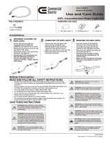
EXPANSION ANCHOR INSTALLATION INSTRUCTIONS ¾” X 5-1/2”
Anchor size is same as drill bit size ( .775" to .787“ )
Use a hammer drill with a Carbide tip, 3/4" diameter, solid drill bit. The bit tip diameter should be to
ANSI Standard B212.15-1994. The Simpson-Tie Strong Bolt 2 wedge anchor is used to resist static, wind
and seismic tension and concrete loads in cracked and uncracked concrete applications, with a compressive
strength of 3,000psi to 8,500psi. Supports Compliance with 2015, 2012, 2009, and 2006, 2003 International
Building Code (IBC); and International Residential Code (IRC). The Strong-Bolt 2 wedge anchors are
torque-controlled, mechanical expansion anchors consisting of an anchor body, expansion clip, nut, and
washer.
Do not disturb, bolt up, or
apply load to adhesive
anchors prior to the full cure of
any adhesive.
Metal anchors and fasteners
will corrode and may lose
load-carrying capacity when
installed in corrosive
environments or exposed to
corrosive materials. There are
many environments and
materials which may cause
corrosion including ocean salt
air, fire-retardants, fumes,
fertilizers, preservative-treated
wood, dissimilar metals, and
other corrosive elements.
Finished Diameters for
Rotary and Rotary Hammer
Carbide Tipped Concrete
Drills per ANSI B212.15
Do not cut or
drill through
a post
tension cable!
(Locate any
post tension
cables before
you drill.)
1.
Hammer Drill a hole to the same
nominal diameter as the expansion
anchor. The hole depth must exceed
the anchor embedment at least ¼”.
Use the baseplate as a drilling
template to ensure proper anchor
locations. (Drill completely through
the concrete floor in case movement
of the lift is required.)
2.
Clean hole completely. Remove dirt
and dust with the use of a shop vac.
or an air compressor.
3.
Assemble the flat washer and nut
flush on the anchor bolt. Drive the
expansion anchor into the hole using
a hammer. If shimming is required,
make sure to leave threads exposed
for proper shimming.
4.
Tighten the nut to the recommended
installation torque.
5.
Installation complete.
REV191230
15

PRE-INSTALLATION PROCEDURES
Before beginning your installation make sure you read the installation manual and insure all instructions and
safety guidelines are fully understood. Check that all component parts are accounted for. Locate the
installation area, identify the center line of the bay and mark the floor. Also mark the center of bay entrance
door. Connect these two points with a short chalk line in the area where lift will be located. Draw a second
chalk line at 90° to locate the positions of both lift columns. (Refer to lift dimensions on this page)
Keep this manual with lift at all times.
DO NO INSTALL LIFT ON ASPHALT OR ANY OTHER
SURFACE THAN A CONCRETE FLOOR CONFORMING TO
THE MINIMUM REQUIREMENTS DETAILED IN THIS
MANUAL. DO NOT INSTALL THIS LIFT ON CONCRETE
WITH SEAMS OR CRACKS OR DEFECT. IF YOU HAVE
ANY QUESTIONS AND CONCERNS WITH THE LIFT
LOCATION SELECTED CONTACT YOUR LOCAL
ARCHITECT.
Use safety protective clothing and protective wear when installing lift.
Installation Tools Required:
▪ 16ft. Measuring tape
▪ Chalk line and chalk
▪ Heavy duty metal wire cutters
▪ 3 ft. Crow bar
▪ Full set of metric wrenches and ratchet set
▪ Full set SAE wrenches and ratchet set
▪ Full set metric and SAE Allen keys
▪ 1-1/8” Socket and Calibrated Torque Wrench
▪ Hammer
▪ Sledge hammer (for installing anchor bolts)
▪ Rubber mallet
▪ Phillip screwdrivers
▪ Flat blade screwdrivers
▪ Snap ring pliers
▪ (2) 12 ft. Step ladders
▪ (1) 4 ft. Level
▪ (1) rotary hammer drill with 3/4” diameter
masonry drill bit
▪ Lifting devices: Use proper lifting devices such
as cranes or a forklift.
▪ 4” x 4” wooden blocks (use for unpacking)
▪ Additional help
▪ Gloves
List of items included in shipment:
▪ 1– Power Side Column
▪ 1– Non-Power Side Column
▪ 2—Lifting Carriages
▪ 2– Cylinders
▪ 1– Crossover Beam Assembly
▪ 1– Long Hydraulic Hose
▪ 1– Medium Hydraulic Hose
▪ 1– Short Hydraulic Hose
▪ 1—Power Unit
▪ 1—Mercury Switch
▪ 4—Lifting Arms
▪ 4—Drop Pins
▪ 4—Lifting Pads
▪ 4—Lift Pad Extension
▪ 1 – Dampener Pad
▪ 2– Safety Latch Assemblies
▪ 2– Safety Covers
▪ 2—Boxes Hardware
▪ 10—Expansion Anchor Bolts 3/4” X 5 –1/2”
▪ 1—Installation Manual
▪ 4—Safety Labels
A qualified person should be consulted to address seismic loads and other local or state requirements.
This car lift is designed for indoor installation, prohibiting outdoor installation of this lift. Approved only
for indoor installation.
REV191230
16

CAR LIFT DIMENSIONS
• IMPORTANT: WIDE SETTING should only be used for specialty fabrication. Not
recommended for standard use.
• It is recommended to use the Narrow and Middle spacing, these are the best application for most
vehicles new lite duty trucks and narrow vehicles.
REV191230
17

CAR LIFT DIMENSIONS
REV191230
18

CAR LIFT GENERAL ASSEMBLY COMPONENTS
REV191230
19

INSTALLATION PROCEDURE WHAT’S INCLUDED:
GENERAL PARTS LIST
Index #
Item Number
Item Description
Quantity
1
QJY245DX.1.1
COLUMN POWERSIDE ASSEMBLY
1
2
QJY245DX.2.1
COLUMN NON-POWERSIDE ASSEMBLY
1
10
GB5783 M10X60mm
HHCS M10X60mm
2
GB97 M10
WASHER M10
2
GB93 M10
LOCK WASHER M10
2
QJY245DX.9-04
M10 THREADED L-BRACKET FOR SAFETY BAR
2
11
GB5783 M12X35mm
HHCS M12X35mm
8
GB97 M12
WASHER M12
16
GB889 M12
NYLON INSERT HEX LOCK NUT M12
8
12
QJY245DS.9-04
ASSEMBLY ATTACHMENT CROSS BEAM- A
1
12
QJY245DS.9-05
ASSEMBLY ATTACHMENT CROSS BEAM- B
1
13
GB5783 M10X30mm
HHCS M10X30mm
8
GB97 M10
WASHER M10
16
GB889 M10
NYLON INSERT HEX LOCK NUT M10
8
14
GB5783 M12X25mm
HHCS M12X25mm
8
GB97 M12
WASHER M12
16
GB889 M12
NYLON INSERT HEX LOCK NUT M12
8
15
QJY245DS.9.2
OVERHEAD CROSSBEAM ASSEMBLY
1
18
QJY245DX.9-02
SAFETY BAR
1
QJY245DX.9-03
SAFETY BAR FOAM COVER
1
19
SP-1447-14
MERCURY LIMIT SWITCH (W/14’ 12-2 AWG CORD)
1
22
QJY245DS-13
SAFETY COVER POWERSIDE
1
23
QJY245DX-03
SAFETY LOCK LEVER
1
GB84141 M10X25mm
HANDLE BALL M10X25mm
1
GB6170 M10
HEX NUT M10
1
24
GB70 M8X12mm
SHCS M8X12mm
8
25
QJY245DS-14
SAFETY COVER NON-POWERSIDE
1
29
QJY245DS-16
ADAPTER BRACKET
2
30
GB70 M8X12mm
SHCS M8X12mm
4
GB97 M8
WASHER M8
4
31
QJY245DX-12
EXTENSION, ADAPTER, 1 1/2 in, 38mm
4
32
QJY245DS-18
EXTENSION, ADAPTER, 3 in, 75mm
4
33
QJY245DS-05
EXTENSION, ADAPTER, 6in, 180mm
4
40
QJY245DX.3-03
SLIDE BLOCK SHIM
10
46
QJY245DX-02
ARM PIN
4
47
GB894 M38
EXTERNAL RETAINING RING M38
4
48D
QJY245DX.4D
SHORT ARM ASSEMBLY (FRONT DRIVER SIDE)
1
48P
QJY245DX.4P
SHORT ARM ASSEMBLY (FRONT PASSENGER SIDE)
1
49
QJY245DX.5
LONG ARM ASSEMBLY (REAR ARM)
2
62-1
QJY245DX.4A
ARM LIFT PAD COMPLETE ASSEMBLY
4
63
STB2-75512
SIMPSON SEISMIC/CRACKED AND UNCRACKED
WEDGE-TYPE EXPANSION ANCHOR
10
REV191230
20
/