MOUNTUP ‎MU2001 Polished Aluminium Single Monitor Wall Mount User manual

Category
Flat panel wall mounts
Type
User manual
Polished Aluminium Single Monitor Wall Mount
Instruction Manual
75x75
100x100
1.5~8kg
3.3~17.6lbs
32"
TPM-MA05-112W-US1.0
If you have any questions , please contact our customer service.
WARNING!
PACKAGE CONTENTS
01
B (x1)
VESA Plate
A (x1)
Arm Assembly
NOTE: Not all hardware included will be used.
D (x3)
Decorative Cover
E(x1)
6mm Allen Key
C (x1)
Bolt
( )
Installation Tools
Level ScrewdriverPencil Drill Socket
Wrench
M-E (x4)
D6 Washer
M-C (x4)M-B (x4) M-D (x4)M-A (x4) M-F (x4)
M6 x 12mmM4 x 16mm M6 x 16mmM4 x 12mm Spacer H5mm
W-B (x3) W-C (x3)
Washer
W-A (x3)
Lag Bolt M6 x 55mm Anchor Φ 9.6 x 43mm
If you have any confusions or are not quite sure about the installation, please do not hesitate to ask for our help.
Before assembly, please check and make sure all necessary accessories are included and undamaged. Improper
installation, such as use the product for monitors over its load capacity or for any purpose not explicitly specied,
may cause damage or serious injury. We would not be liable for any damage or injury caused by improper
mounting or inappropriate use.
The kit contains small items that could be choking hazards if swallowed. Please keep them OUT OF REACH OF
CHILDREN UNDER 3 YEARS OLD. ADULT SUPERVISION IS REQUIRED.
Stud
Finder
Awl Wood Drill
ø3/16"(ø4.5mm)
Wood Stud Installation
Hammer
Concrete Installation
Concrete Drill
ø3/8"(ø10mm)
ASSEMBLY STEPS
02
STEP 1: Attach Arm Assembly to Wall
OPTION A: Wood Stud Installation
ø 4.5mm
3/16")
55mm
(2.2")
X
W-C W-A
Caution:
Do not use anchor in drywall
or wood
A
A
Locate your studs. Verify and mark
Position the Arm Assembly (A) at your
desired height and line up the holes
with your stud center line. Level the
Arm Assembly (A) and mark the pilot
hole locations.
Drill pilot holes using a ø3/16 in.
(ø4.5 mm) diameter drill bit.
Install Arm Assembly (A) using lag
bolts (W-A) and washers (W-C).
Tighten the lag bolts until they are
Assembly (A).
No!
03
STEP 1: (Continued)
60mm
(2.4")
ø10mm
(ø 3 /8")
A
A
OPTION B: Solid Concrete Wall Installation
60mm (2.4 )
Position the Arm Assembly (A) at
your desired height , level the Arm
Assembly (A) and mark the pilot hole
locations.
Drill pilot holes using a ø3/8 in.
(ø10 mm) diameter drill bit.
Install Arm Assembly (A) using lag
bolts (W-A), anchors (W-B) and
washers (W-C). Tighten the lag bolts
the Arm Assembly (A).
No!
W-C W-A
W-B
04
STEP 2: Attach Decorative Cover
Attach Decorative Covers (D) to Lag Bolts (W-A).
D
W-A
NOTE: Hand tighten screws to avoid over tightening.
STEP 3 : Attach Monitor
05
OPTION B: Curved Back Monitor
Attach the VESA plate (B) to back of monitor and secure
with screws (M-B) or (M-D) with washers (M-E)and
OPTION A: Flat Back Monitor
Attach the VESA plate (B) to back of monitor and
secure with screws(M-A)or(M-C) with washers(M-E)
washers(M-F)using 6 mm Allen Key (E). Do not tighten the
screws excessively or your monitor might be damaged.
using 6 mm Allen Key (E). Do not tighten the screws
excessively or your monitor might be damaged.
M-A
M-C
M-E
E
B
Monitor Monitor Monitor
M-B
M-D
M-E
M-F
E
B
Monitor Monitor Monitor
No!
No!
07
Slide the monitor onto the head of swivel arm, install the security bolt (C). Make sure the security
bolt is installed before you rotate the monitor.
STEP 4: Hang Monitor
Q
C
Important Notice:
The gas spring is pre-set to minimum tension. Once the monitor is hanged on, hold the
monitor with both hands and DO NOT let go suddenly or immediately. Instead, leave the
monitor in a slow & gentle way while observing whether the arms will fall down wildly.
Guideline to adjust monitor tilting angle.
Solution:
1. Loosen the tilting bolt.
2. Hold the bottom of monitor with
one hand and adjust to determine
your desired tilt angle.
3. Retighten the tilting bolt to x
the intended angle.
Problem:
If monitor face down
07
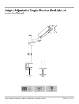
STEP 5: Adjust Tension
Note1:
Be sure to keep the arm in horizontal position during adjustment.
CAUTION
As for how many circles the screw should be turned, the table below is for reference.
Note2:
E
Monitor Weight 1.5kg 3kg 4kg 5kg 6kg 7kg 8kg
Circles (AT LEAST) 108643min 12
Situation 1: Arm falls down
Solution:
Upper Arm with monitor falls down and fails to stay where intended.
Turn the inside screw counterclockwise(“+”direction) to increase gas spring
tension until the arm can stay as intended.
Situation 2: Arm rises up
Solution:
Upper Arm with monitor rises up and fails to stay where intended.
Turn the inside screw clockwise(“-”direction) to decrease gas spring tension
until the arm can stay as intended.
For intended functioning of the mount, you may need to adjust the tension of Upper Arm (A) in accordance
with your monitor weight by 6 mm Allen Key (E).
08
STEP 5: (Continued)
STEP 6: Cable Management
For lower arm: Insert the cable and slide the cable cover down;
For upper arm: Insert the cable and press the tabs on the inside of the cable cover slightly inward and slide
down to reattach the cable cover.
Attach Cable Cover
1
2
Slide
Press
+90°
Adjust as Desired
09
-45°
max280mm
360°
180°
Adjust monitor position and rotation.
180°
Tilt
Swivel
Rotation
Height
Swivel
Swivel
Swivel
Rotation
Height
Tilt
Note: To ensure stability, the tightness of the rotating axis has been
preset, so it would be kind of dicult to rotate the VESA plate.
Suggestion: Please attach the monitor rst, then hold the two sides
of it with both hands, and rotate vigorously.
If that doesn't work out, please do not hesitate to ask for our help.
360°
Product Dimensions
10
2.6"
0.9"
7.3"
2.4"
2.9"
"9.2
"9.3
"5.4
"
11
3.9"
4.5"
"7.6
8.7"-10.8"
-45°
+90°
180°
360°
180°
360°
CAUTION AND MAINTENANCE:
Never allow children to climb, stand, hang, or play on any part of monitor or stand.
This product is intended for indoor use only. Using this product outdoors could lead to
product failure and personal injury.
Check that the bracket is secure and safe to use at regular intervals (at least every three months).
  • Page 1 1
  • Page 2 2
  • Page 3 3
  • Page 4 4
  • Page 5 5
  • Page 6 6
  • Page 7 7
  • Page 8 8
  • Page 9 9
  • Page 10 10
  • Page 11 11
  • Page 12 12

MOUNTUP ‎MU2001 Polished Aluminium Single Monitor Wall Mount User manual

Category
Flat panel wall mounts
Type
User manual

Ask a question and I''ll find the answer in the document

Finding information in a document is now easier with AI