Evolveo Detective DV4 Owner's manual
- Category
- Digital Video Recorders (DVR)
- Type
- Owner's manual

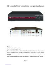
Detective DV4
www.evolveo.com

Statement:
Thanks for purchasing from us. Please feel free to contact our service whenever
you need help.
This manual is applicable for NVR products. Features and functions vary with
different products, please refer to our physical commodity and the fast manual.
This manual is your reference for operations and encodings. Related
functions, specific orders, detailed menu-tree as well as fast manual are
included. Please read it before installation or use.
This manual might contain some technical or print errors. Any enhancement in product
features shall be added into the manual consistently without further notice.
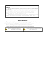
Safety Instruction
This manual is intended to ensure that user can use the product properly without danger or any
property loss. Please read it carefully and take care of it for further reference.
Precaution measures are divided into “warnings” and “cautions”, as below:
Warnings: Neglecting any of the warnings may cause death or serious injury.
Cautions: Neglecting any of the cautions may cause injury or equipment damage.
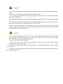
Warning:
Follow these safeguards to
avoid death or serious injury.
Caution: Follow these precautions to prevent
injury or property loss.

Warnings
1. Electrical safety regulations of the nation and the region must be strictly followed during installation
or use.
2. Please use the matched power adapter from standard company.
3. Do not connect multiple DVRs with one single power adapter (Overload for adapter may lead to
over-heat or fire hazard.
4. Shut down the power while connecting or dismounting the speed dome. Do not operate with power
on.
5. Shut down the power and unplug the power cable immediately when there is smoke, odor or noise
rising from the DVR. Please contact the dealer or service center.
6. Please contact the local dealer or latest service center when DVR works abnormally. Do not attempt
to disassemble or modify the device yourself. (We shall shoulder no responsibility for problems caused
by unauthorized repair or maintenance.
Cautions
1. Do not drop anything onto the dome, avoid it from physical strike. Keep it away from high
electromagnetism radiation surroundings. Do not install it at vibration surface or places subjecting to
strike. (Ignorance can cause equipment damage)
2. Keep it away from rain and moisture
3. Avoid exposing to direct sunlight, poor-ventilation or heat source such as heater, radiator.
(Ignorance can cause fire hazard)
4. To avoid physical damage, extreme environment such as lampblack, water vapor, too hot or dusty
are not allowed.
5. Please use soft and dry cloth to clean the shell. Use neutral cleaner instead of alkaline when the
dirt is difficult to get rid of.

Directory
1 Product Introduction .............................................................................................................................................6
1.1 Product overview ..........................................................................................................................................6
1.2 Main functions ..............................................................................................................................................6
2 Open-package check and cable connections...................................................................................................7
2.2 Hard disk installation ....................................................................................................................................8
2.3 Shelf installation ...........................................................................................................................................8
2.4 Front panel ....................................................................................................................................................9
2.5 Rear panel ...................................................................................................................................................10
2.6 Audio and video input and output connections ...........................................................................................12
2.6.1 Video input connections ..............................................................................................................12
2.6.2 Video output connections and options ......................................................................................12
2.6.3Audio signal input ..........................................................................................................................12
2.6.4Audio signal output........................................................................................................................12
2.7 Alarm input and output connections ...........................................................................................................13
2.7.1 Alarm input port specification......................................................................................................15
2.7.2 Alarm output port specification ...................................................................................................15
2.7.3 Alarm output port relay parameters ...........................................................................................15
2.8 Device attachment.......................................................................................................................................16
3 Basic operation....................................................................................................................................................16
3.1 Turn on ........................................................................................................................................................16
3.2 Turn off .......................................................................................................................................................17
3.3 System Login ..............................................................................................................................................17
3.4 Preview .......................................................................................................................................................18
3.5 Desktop shortcut menu................................................................................................................................19
3.5.1 Main menu.....................................................................................................................................20
3.5.2 Record Control..............................................................................................................................22
3.5.3 Playback ........................................................................................................................................23
3.5.5 Alarm output ..................................................................................................................................25
3.5.6 PTZ control ....................................................................................................................................26
3.5.7 Color setting ..................................................................................................................................31
3.5.8 Output Adjust.................................................................................................................................32
3.5.9 Logout ............................................................................................................................................33
4.1 Main menu navigation ................................................................................................................................33
4.2 Record .........................................................................................................................................................36
4.2.1Playback .........................................................................................................................................37
4.2.2 Backup ...........................................................................................................................................37
4.3 Alarm Function ...........................................................................................................................................39
4.3.1 Motion Detect ................................................................................................................................39
4.3.2 Video Blind ....................................................................................................................................42
4.3.3 Video Loss .....................................................................................................................................42

4.3.4 Alarm input.....................................................................................................................................43
4.3.5 Alarm output ..................................................................................................................................44
4.3.6 Abnormal........................................................................................................................................44
4.4 System setup ...............................................................................................................................................45
4.4.1 General ..........................................................................................................................................46
4.4.2 Network setup ...............................................................................................................................47
4.4.3 Net Service ....................................................................................................................................48
4.4.4 Output mode .................................................................................................................................57
4.4.5 Serial port settings........................................................................................................................58
4.4.6 Tour.................................................................................................................................................59
4.4.7 Channel manage ..........................................................................................................................59
4.5 Advanced.....................................................................................................................................................66
4.5.1 HDD Manage ................................................................................................................................66
4.5.2 Account ..........................................................................................................................................67
4.5.3 Online user ....................................................................................................................................70
4.5.4 Output adjust.................................................................................................................................70
4.5.5 Auto Maintain ................................................................................................................................71
4.5.6 Restore...........................................................................................................................................71
4.5.7 Upgrade .........................................................................................................................................72
4.5.8 Device Info.....................................................................................................................................72
4.5.9 Import / Export ..............................................................................................................................72
4.6 Info ..............................................................................................................................................................73
4.6.1 HDD info ........................................................................................................................................73
4.6.2 BPS.................................................................................................................................................74
4.6.3 LOG ................................................................................................................................................75
4.6.4 Version ...........................................................................................................................................76
4.7 Shut down system .......................................................................................................................................77
5 Cloud Technology Basic Operation ..................................................................................................................77
6 FAQ and maintenance .......................................................................................................................................82
6.1 FAQ.............................................................................................................................................................82
6.2 Maintenance ................................................................................................................................................88
Appendix 1.Remote controller operation ............................................................................................................89
Appendix 2.Mouse operation................................................................................................................................90
Appendix 3.Hard disk capability calculation .......................................................................................................91

7 / 91
1 Product Introduction
1.1 Product overview
The series NVR is designed specially for security and defense field which is an outstanding digital
surveillance product. It introduces embedded LINUX operating system which is more stable. It introduces
standard H.264mp video compressed format and unique space-time filtering algorithm which insures the
high quality image, low error coding ratio and single frame playing. It introduces TCP/IP network
technology which achieves the strong network communication ability and telecommunication ability.
The series NVR can be used individually or online applied as a part of a safety surveillance network.
With the professional network video surveillance software it achieves the strong network communication
ability and telecommunication ability.
The series DVR can be applied in the bank, telecom, electric power system, judicial system,
transportation, intelligent housing, factory, storehouse, water conservancy and so on.
1.2 Main functions
Real-time surveillance
Spot interface, analog interface, VGA interface and HDMI interface surveillance function through monitor
or display.
Storage
Non-working disk dormancy processing which is convenient to radiate heat, reduce power and extend the
life-span
Special storage format which insures the data safety
Compression
Real-time compression by individual hard disk which insures the audio and video signal stable
synchronization
Backup
Through SATA interface and USB interface such as USB equipment, removable hard disk and so on
Through net download the files in the hard disk
Playback
Individual real-time video recording as well as searching, playback, network surveillance, recording check,
downloading and so on
Multi-playback mode

8 / 91
Zoom at arbitrary region
Net operating
Through net (including telephone) tele-surveillance in the real time
Tele-PTZ control
Tele-recording check and real-time playback
Alarm linkage
Alarm activated video record, tour, message, buzzer, e-mail, ftp, cell phone to report
Communication interface
RS485 interface which fulfills the alarm input and PTZ control
RS232 interface which can extend keyboard connection to realize master, as well as with computer serial
port connection for system maintenance and upgrade, and matrix control and so on.
Standard Ethernet network interface which fulfills the telecommuting function
Intelligent operating
Mouse action function
Fast copy and paste operating for the same setting

9 / 91
2 Open-package check and cable connections
2.1 Out of box audit
When you receive the product,
Materials used for the package of the NVR can protect most accidental clashes during transportation.
Then, please open the box and get rid off the plastic protective materials. Check whether there is any
visible damage to the NVR appearance.
At last, please open the machine crust and check the data wire in the front panel, power wire, the
connection between the fan power and the main board.
1. Front panel and rear panel
The key function specification in the front panel and the interface specification in the real panel
are in the specification.
Please check the product type in the front panel whether is accordant with the product type you
order.

10 / 91
The label in the real panel is very important for the after service. Please protect it carefully. When
you contact us for after service, please provide the product type and serial number in the label.
2. Check
After open the cover, you should check if it has obvious damage trace, also please check the
front panel data cable, power cord and motherboard's connection are loose or not.
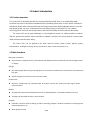
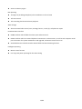
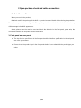
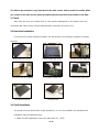
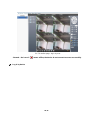
2.2 Hard disk installation
For the first use, please install the hard disk, this machine box can install two hard disk (no limited
capacity).
①disassemble the screw ②disassemble the cover ③fix the screw of hard disk
④fix the screw of hard disk ⑤connect the data wire ⑥connect the power wire
⑦cover the machine ⑧fix the cover
2.3 Shelf installation
This product chassis specification for the standard 1u, so it can be installed in the standard shelf.
Installation steps and attention items:
1、Make sure the temperature in the room lower than 35℃ (95
°
f).

11 / 91
2、Keep the equipment have 15cm (6 inches) space around in order to air's circulation.
3、From bottom to shelf installation.
4、When multiple components install in the frame please take preventive measures to avoid
power socket overload.
2.4 Front panel
The front panel of economical equipment
(1) Power indicator light
(2) Record indicator light
(3)Alarm indicator light
(4) ESC
(5) Menu
(6)Direction &Enter
The front panel of standard equipment
(1)
IR remote
receiver
(2)
Power indicator
light
(3)
Alarm indicator
light
(4)
Keyboard
indicator light
(5)
Record indicator
light
(6)
Network indicator
light
(7)
Status indicator
light
(8)
Previous File
(9)
Return main
menu
(10)
PTZ
(11)
Playback
(12)
Previous File
(13)
Next file
(14)
Record
(15)
Slow Play
(16)
Playback pause
(17)
Fast Play
(18)
Play back Stop
(19)
Direction&Enter
(20)
USB
(21)
Stop Play
(22)
ESC
(23)
Power Switch

12 / 91
The front panel of enhanced equipment
(1) Shuttle
(2) Play Pause (3) Slow Play (4) Fast Play (5) Backwards Pause (6) Play back Stop
(7) Record (8)
Power switch (9) USB mouse (10)
Indicator light (11) Main menu (12)Scene switch
(13) Record check (14) PTZ (15) Assist (16) Shift (17) ESC (18) IR remote receiver (19) Direction
The front panel of high-end equipment
(1) Direction (2) Play Pause (3) Previous File (4) Next File (5) Backwards Pause (6) Play back
Stop (7) Record check (8) Alarm output
(9) Camera narrow (10)
Camera zoom (11) Preset point set
(12) USB (13) ESC (14) Scene switch (15) Record (16) PTZ (17) Menu (18) Assist (19) Shift
(20)
Power switch (21)
Indicator light (22) IR remote receiver
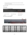
2.5 Rear panel
The rear panel of economic and standard equipment

13 / 91
(1) Audio output (2) HDMI (3) USB (4) RS485 (5) Power (6) BNC (7) VGA (8) Network
The rear panel of enhanced equipment
(1) Audio Input (2) HDMI (3) USB (4) Network (5) VGA (6) External Interface (7) Power Supply
(8) BNC (9) Audio Input (10) RS485 (11) Power switch
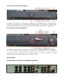
The rear panel of high-end equipment
(1) Power (2) Cooling mouth (3) Audio Input (4) Video output (5) Power switch (6) VGA Interface (7) HDMI
(8) Network (9) USB (10) External (11) Audio output
2.6 Audio and video input and output connections
2.6.1 Video input connections
There is no video input connection.
Insure the vision signal stable and credible
The vision should be installed in the appropriate location where is away from backlighting and low
illumination or adopts the better backlighting and low illumination compensation.
The ground and power supply of the vision and the DVR should be shared and stable.

14 / 91
2.6.2 Video output connections and options
The video output is divided into PAL/NTSC BNC (1.0V
P-P
, 75Ω) and VGA output
(selective configuration).
When replace the monitor by the computer display, there are some issues to notice
1. Do not stay in the turn-on state for a long time.
2. Keep the computer display normal working by demagnetizing regularly.
3. Stay away from the electromagnetic Interference.
TV is not a credible replacement as a video output. It demands reducing the use time and control the
power supply and the interference introduced by the nearby equipment strictly. The creepage of low quality
TV can lead to the damage of other equipments.
2.6.3 Audio signal input
Audio port is BNC connection.
The input impedance is high so the tone arm must be active.
The audio signal line should be firm and away from the electromagnetic Interference and connected
credible which avoid false and joint welding and oxidation. The high voltage current should be avoided
especially.
2.6.4 Audio signal output
Commonly the output parameter of DVR audio signal is greater than 200mv 1KΩ (BNC) which can
connect the low impedance earphone and active sound box or other audio output equipments through

15 / 91
power amplifier. If the sound box and the tone arm cannot be isolated, howling phenomena is often
existed. There are some methods to deal with the above phenomena.
1. Adopt better directional tone arm.
2. Adjust the sound box volume to be under the threshold that produces the howling phenomena.
3. Use fitment materials that absorb the sound to reduce reflection of the sound.
4. Adjust the layout of the sound box and the tone arm.
2.7 Alarm input and output connections
Before connecting the device, please pay attention to follow situations:
*note: Some products have no alarm input/output functions.
1.Alarm input
A. Alarm input is grounding alarm input.
B. Alarm input demand is the grounding voltage signal.
C. When the alarm is connected with two DVRs or connected with DVR and other equipments, it
should be isolated by relay.
2. Alarm output
Alarm output cannot be connected with high-power load (no more than 1A).When forming the output
loop it must prevent the big current from relay damage. Use the contact isolator when there is a
high-power load
3. PTZ decoder connections
A. The grounding of the PTZ decoder and DVR must be shared otherwise the common-mode
voltage will lead to the PTZ control failure. The shielded twisted pair is recommended.
B. Avoid the entrance of high voltage. Make the layout reasonably. Take precaution from the
thunder.
C. In the outlying end connect 120Ω resistance paralleled to reduce the inflection and insure the
signal quality.
D. The 485 AB lines of DVR cannot connected with other 485 output equipments paralleled.
E. The voltage between the AB lines of the decoder must be less than 5V.
4. Front equipment grounding note
Bad grounding can lead to the burnout of the chip.
5. Alarm input type unlimited

16 / 91
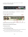
The NVR alarm output port is constant opening type.
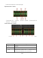
Eight external alarm interface
(1) Alarm input 1,2,3,4 (2) ground (3) RS232 (4) RS485 (5) Alarm input 5,6,7,8
(6) Ground (7) Alarm output
Sixteen external alarm interface
①⑥⑧alarm input ②⑦ground ③alarm output ⑤RS485 ④RS232
Parameter
meaning
G
grounding
R,T
RS232 port
A,B
485communciate interface which is connected with the
recording control equipments such as the decoder

17 / 91
2.7.1 Alarm input port specification
8 channels alarm input. Alarm input type unlimited.
The grounding and the com port of the alarm sensor are parallel (The alarm sensor is external power
supply).
The grounding of the alarm and the DVR should be shared.
The NC port of the alarm sensor must be connected with the DVR alarm input port.
The grounding of the power supply and the alarm sensor must be shared when used in external power
supply.
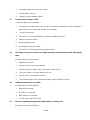
2.7.2 Alarm output port specification
2 channels alarm output. There is external power supply when using the external alarm equipment.
Please refer to the relay relevant parameters to avoid the overload that damages main machine.
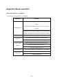
2.7.3 Alarm output port relay parameters
Type:JRC-27F
Interface material
silver
rating
(resistance load)
Rating switch capacity
30VDC 2A, 125VAC 1A
maximal switch power
125VA 160W
maximal switch voltage
250VAC, 220VDC
maximal switch current
1A
isolation
Homo-polarity interface
1000VAC 1minute
Inhomo-polarity
1000VAC 1 minute
Interface and winding
1000VAC 1 minute
Surge voltage
Homo-polarity interface
1500VAC (10
×
160us)
Turn-on time
3ms max
Turn-off time
3ms max
longevity
mechanical
50×106
MIN(3Hz)
electric
200×103
MIN (0.5Hz)
Environment
-40~+70℃

18 / 91
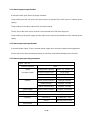
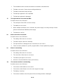
2.8 Device attachment
1. Connect the 485 lines of the speed dome with the DVR 485 interface.
The 485 interface of eight external alarm
The 485 interface of sixteen external alarm
2. Connect the video line with the DVR video input.
3. Electrify the speed dome
3 Basic operation
Note: The button in gray display indicates nonsupport.
3.1 Turn on
Plug the power supply and turn on the power supply switch. Power supply indicator light shining
indicates turning on the video recorder. After the startup you will hear a beep. The default setting of video
output is multiple-window output mode. If the startup time is within the video setting time, the timing video
recording function will start up automatically. Then the video indicator light of corresponding channel is

19 / 91
Shining and the DVR is working normally.
Note:1. Make sure that the input voltage corresponds with the switch of the DVR power supply.
2. Power supply demands: 220V
±
10% /50Hz.
Suggest using the UPS to protect the power supply under allowable conditions.
3.2 Turn off
There are two methods to turn off the DVR. Entering [main menu] and choosing [turn off] in the [turn
off the system] option is called soft switch. Pressing the power supply switch is called hard switch.
Illumination:
1. Auto resume after power failure
If the DVR is shut down abnormally, it can automatically backup video and resume previous
working status after power failure.
2. Replace the hard disk
Before replacing the hard disk, the power supply switch in the real panel must be turned off.
3. Replace the battery
Before replacing the battery, the setting information must be saved and the power supply switch
in the real panel must be turned off. The DVR uses button battery. The system time must be checked
regularly. If the time is not correct you must replace the battery, we recommend replacing the battery
every year and using the same battery type.
Note: The setting information must be saved before replacing the battery otherwise
information will lose.
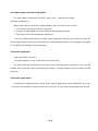
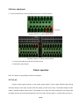
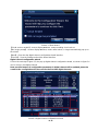
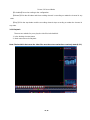
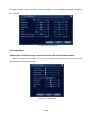
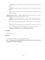
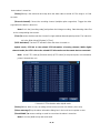
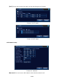
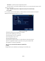
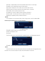
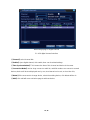
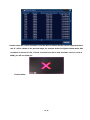
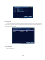
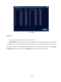
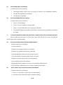
3.3 System Login
When the NVR boots up, the user must login and the system provides the corresponding functions
with the user purview. There are two user settings. The names are admin, and default and these names
have no password. Admin is the super user purview; default’s permissions are preview and video
playback. User admin’s password can be revised, while their permissions can’t be revised; user default
is the default login user whose permission can be revised but not its password.

20 / 91
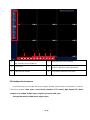
1
Recording status
3
Video loss
2
Motion detect
4
Camera lock
Picture 3.1 System Login
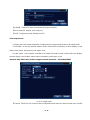
Password protection: If the password is continuous wrong five times, the alarm will start. If
the password is continuous wrong five times, the account will be locked. (Through reboot or after
half an hour, the account will be unlocked automatically).
For your system security, please modify your password after first login.
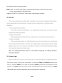
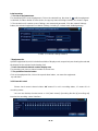
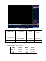
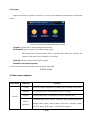
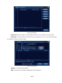
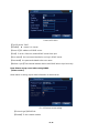
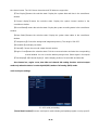
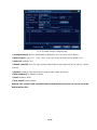
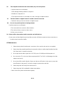
3.4 Preview
You can right click mouse to choose the switch between the windows.
The system date, time and channel name are shown in each viewing window. The surveillance video
and the alarm status are shown in each window.
Table 3.1 Preview icon

21 / 91
1
2 3 4 5 6
(1)
Channel name and status display, click on
the "channel" can be folded up.
(2)
More than one scene changes
(3)
Full screen
(4)
Page flip up and down, when choosing a 16
channel, operation can be performed.
(5)
Play/close all channel
(6)
Full channel video/close full video
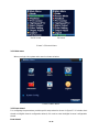
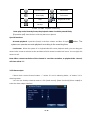
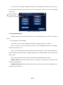
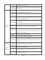
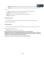
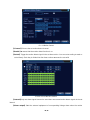
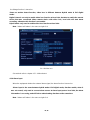
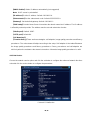
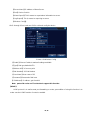
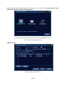
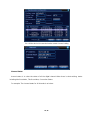
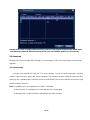
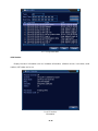
3.5 Desktop shortcut menu
In preview mode you can right click mouse to get a desktop shortcut menu, as the picture 3.2 shows.
The menu includes: main menu, record mode, playback, PTZ control, High Speed PTZ, Alarm
Output, color Setting, Output adjust, Logout, view mode shift ,spot.
*Only partial model of 6000 series support Spot
Page is loading ...
Page is loading ...
Page is loading ...
Page is loading ...
Page is loading ...
Page is loading ...
Page is loading ...
Page is loading ...
Page is loading ...
Page is loading ...
Page is loading ...
Page is loading ...
Page is loading ...
Page is loading ...
Page is loading ...
Page is loading ...
Page is loading ...
Page is loading ...
Page is loading ...
Page is loading ...
Page is loading ...
Page is loading ...
Page is loading ...
Page is loading ...
Page is loading ...
Page is loading ...
Page is loading ...
Page is loading ...
Page is loading ...
Page is loading ...
Page is loading ...
Page is loading ...
Page is loading ...
Page is loading ...
Page is loading ...
Page is loading ...
Page is loading ...
Page is loading ...
Page is loading ...
Page is loading ...
Page is loading ...
Page is loading ...
Page is loading ...
Page is loading ...
Page is loading ...
Page is loading ...
Page is loading ...
Page is loading ...
Page is loading ...
Page is loading ...
Page is loading ...
Page is loading ...
Page is loading ...
Page is loading ...
Page is loading ...
Page is loading ...
Page is loading ...
Page is loading ...
Page is loading ...
Page is loading ...
Page is loading ...
Page is loading ...
Page is loading ...
Page is loading ...
Page is loading ...
Page is loading ...
Page is loading ...
Page is loading ...
Page is loading ...
Page is loading ...
Page is loading ...
Page is loading ...
Page is loading ...
-
 1
1
-
 2
2
-
 3
3
-
 4
4
-
 5
5
-
 6
6
-
 7
7
-
 8
8
-
 9
9
-
 10
10
-
 11
11
-
 12
12
-
 13
13
-
 14
14
-
 15
15
-
 16
16
-
 17
17
-
 18
18
-
 19
19
-
 20
20
-
 21
21
-
 22
22
-
 23
23
-
 24
24
-
 25
25
-
 26
26
-
 27
27
-
 28
28
-
 29
29
-
 30
30
-
 31
31
-
 32
32
-
 33
33
-
 34
34
-
 35
35
-
 36
36
-
 37
37
-
 38
38
-
 39
39
-
 40
40
-
 41
41
-
 42
42
-
 43
43
-
 44
44
-
 45
45
-
 46
46
-
 47
47
-
 48
48
-
 49
49
-
 50
50
-
 51
51
-
 52
52
-
 53
53
-
 54
54
-
 55
55
-
 56
56
-
 57
57
-
 58
58
-
 59
59
-
 60
60
-
 61
61
-
 62
62
-
 63
63
-
 64
64
-
 65
65
-
 66
66
-
 67
67
-
 68
68
-
 69
69
-
 70
70
-
 71
71
-
 72
72
-
 73
73
-
 74
74
-
 75
75
-
 76
76
-
 77
77
-
 78
78
-
 79
79
-
 80
80
-
 81
81
-
 82
82
-
 83
83
-
 84
84
-
 85
85
-
 86
86
-
 87
87
-
 88
88
-
 89
89
-
 90
90
-
 91
91
-
 92
92
-
 93
93


Evolveo Detective DV4 Owner's manual
- Category
- Digital Video Recorders (DVR)
- Type
- Owner's manual
Ask a question and I''ll find the answer in the document
Finding information in a document is now easier with AI
Related papers
-
Evolveo DETECTIVE S4CIH Owner's manual
-
-
-
-
-
-
-
-
-
Other documents
-
Conceptronic C4CHCCTVKITD Product information
-
 Godrej Appliances eyetrace elite ET-4D12E User manual
-
Security Tronix ST-DVR4CH User manual
-
 ZUUM Media DVR8C-41AL41A-H-500G-BK User's Installation And Operation Manual
-
 Avtronix AD-808Q User manual
-
 Hi-view ME Series User's Installation And Operation Manual
-
Optiview C Series User's Installation And Operation Manual
-
Acumen Ai-F4343 User manual
-
Smartwares EL430DVR Owner's manual
-
 Domar Hybrid User manual


