
INSTRUCTIONS FOR INSTALLATION, OPERATION AND MAINTENANCE
Fire Damper
ETPR


FläktGroup DC_9938GB 20210830_R3 Specifications are subject to alteration without notice.
Fire Damper ETPR - Instructions for Installation, Operation and Maintenance
3
Maintenance Check List:
Installation
Fire damper ETPR must be installed according to this in-
stallation manual, see pages 4-9.
General instructions for using hangers
The fire damper must be supported so that the ductwork
connected to the damper does not impose any load on the
damper body.
In practice, a good way to fit the product centrally in the
installation opening is to hang the ductwork prior to sealing.
If the subsequent sealing is done using grouting concrete,
also other types of support can be used during installation
until the concrete has dried.
It is essential that no stress is imposed on the fire damper
or the duct. The hanging and fixing solution must be ade-
quate in the event of fire. The hanger must be located either
at the fire damper or immediately after the duct connection.
Designing the use of hangers is the responsibility of a
structural engineer.
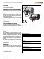
Operation and function testing
According to CE marking, a fire damper must always be
equipped with a tripping mechanism based on temperature.
Fire dampers can be delivered equipped with either a fuse
mechanism or an actuator.
ETPR motorized fire dampers may additionally be linked to
a smoke detection based tripping mechanism. A tripping
system based on smoke detection is easy to install using
FläktGroup FICO control and monitoring system. The FICO
system can also be used for automatic function tests of fire
dampers.
The function testing for the motorized damper can be per-
formed by cutting off the power supply by using the switch
of the thermal trip connected to the motor. The spring will
then close the damper. The function testing can also be
done by means of the control and monitoring system FICO,
either manually or automatically. The recommended auto-
matic function testing interval for the motorized damper is
48 hours.
The operation of the fuse mechanism is tested by pushing
the red test button – the spring will close the blade. Beware
of the reset handle as it will rotate rapidly during test op-
eration. To reset the mechanism, turn the handle until the
mechanism clicks.
Maintenance
The function testing interval is always determined separate-
ly for each building, but testing must be carried out at least
twice a year according to product standard EN 15650:2010
(see example of check list beside).
WARNING! Never put your hands inside the damper while
it is closing.
Clean the fire damper by means of a vacuum cleaner. Avoid
chemical cleaning agents.
Fire damper reference
Date of inspection
Check actuator wiring for damage (where applicable)
Check end-switch wiring for damage (where applicable)
Check fire damper cleanliness and clean where necessary
Check the condition of blades and seals, rectify and report where
necessary
Confirm the safety closure operation of the fire damper according
to the manufacturer’s instructions
Confirm operation of damper to OPEN and CLOSE by use of the
control system and physical observation of the fire damper, rectify
and report where necessary
Confirm operation of OPEN and CLOSED end-switches, rectify and
report where necessary
Confirm that the fire damper fullfills its function as a part of the
control system (where applicable)
Confirm that the fire damper is left in its normal working position
NOTE! A fire damper is usually part of a system. As this is the
case, the whole system should be checked as governed by the
operation and maintenance requirements for the system.
Spare parts
Actuator: see type specification on the actuator.
Fuse part ETFF-99-01
Fuse part replacement, see page 11.

FläktGroup DC_9938GB 20210830_R3 Specifications are subject to alteration without notice.
Fire Damper ETPR - Instructions for Installation, Operation and Maintenance
4
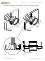
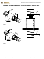
Installation into building elements with fire classification EI 60 (Ø100 - Ø630)
Figure 1 Figure 2
Figure 4Figure 3
ØD
≥100 mm
M
≥110 mm
≥ 200 mm
M
≥116 mm
ØD
S
S

FläktGroup DC_9938GB 20210830_R3 Specifications are subject to alteration without notice.
Fire Damper ETPR - Instructions for Installation, Operation and Maintenance
5
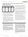
Size ØD (mm) Installation opening Ø (mm)
100
125
150
160
200
250
300
315
400
500
630
175 – 195
175 – 195
200 – 220
210 – 230
250 – 270
300 – 320
350 – 370
365 – 385
450 – 470
550 – 570
680 – 700
Size ØD (mm) Installation opening Ø (mm)
100
125
150
160
200
250
300
315
400
500
630
135 – 137
135 – 137
160 – 162
170 – 172
210 – 212
260 – 262
310 – 312
325 – 327
410 – 412
510 – 512
640 – 642
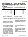
Installation of fire damper into rigid
building elements (walls and intermediate
floors) with fire classification EI 60 and
into floors with fire classification EI 90
(Fig. 1 and Fig. 4)
Installation of fire damper into flexible
building elements (gypsum board walls
or similar) with fire classification EI 60
(Fig. 2 and Fig. 3)
2. The fire damper blade must be closed during installa-
tion.
3. Place the circular duct centrally in the opening.
4. Place the fire damper in the duct so, that the damper
flange rests against the building element and connect
the damper to duct. Use screws of sufficient length (e.g.
M6 x 40 mm), which are suited for rigid construction, to
fasten the damper to the building element through the
bendable brackets on the flange. The damper must be
fastened at 4 brackets at the minimum. The blade shaft
can be placed in any position.
5. Completely fill the gap M between the duct and the
building element using incombustible, rock based, fine-
grained gypsum or concrete cast. Protect the damper
whilst infilling.
2. The fire damper blade must be closed during installa-
tion.
3. Place the circular duct in the opening.
4. Fill the gap S between duct and wall opening on both
sides by using fire-resistant mass.
5. Place the fire damper in the circular duct so, that the
damper flange rests against building element and
connect the damper to duct. Use screws or anchors
suited for gypsum board walls to fasten the damper to
the building element through the bendable brackets on
the flange. The damper must be fastened at 4 brackets
at the minimum. The blade shaft can be placed in any
position.
6. Check the functioning of the fire damper and proper
movement of the blade. Clean the damper, if necessary.
Place plastic covers on the openings and keep them
covered, until ducts are connected to the damper.
7. To reset the fuse mechanism: Turn the handle towards
the OPEN position until the mechanism clicks and the
blade locks into position.
8. Manual function testing of the motorized fire damper
can be performed with the tool delivered with the
actuator. When connected to a power supply, function
testing is done by using the switch of the thermal trip.
NOTE! If you open the damper blade manually with the
tool, be sure to release the damper back to the closed
position before switching on power.
9. Connect ducts to the damper according to the instruc-
tions provided by the designer and the manufacturer.
Use rivets of sufficient length (e.g. DIN 7337 4x10 or
shorter) to lock fire damper to the duct. Note! Always
check that damper blade can rotate freely and rivets/
screws are out of the way. Access panel should be
placed next to the fire damper to enable necessary
cleaning and inspection. Suspend the ducts according
to instructions from the manufacturer and ensure that
the ductwork does not cause any load on the damper
installation.
10. If the fire damper is used as an air transfer or air
terminal device, it must be equipped with a protective
grille. The distance between the grille and the damper
blade in the open position must be at least 30 mm. In
case of large fire dampers, an extension piece must
be installed between the grille and the damper blade.
A circular duct of suitable length can be used as an
extension piece.
11. When dampers are to be mounted next to one another,
the distance between the dampers should be ≥200mm
(Figure 4).
1. Installation opening in the rigid wall or intermediate
floor must comply with the dimensions given in the
table below.
1. Installation opening in the flexible wall must comply
with the dimensions given in the table below.

FläktGroup DC_9938GB 20210830_R3 Specifications are subject to alteration without notice.
Fire Damper ETPR - Instructions for Installation, Operation and Maintenance
6
Figure 5
Figure 6
Figure 7
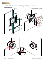
Installation outside building elements with fire classification EI 60 (Ø100 - Ø630)
ØD
M
≥100 mm
1
≥116 mm
ØD
1
S
M
2
2

FläktGroup DC_9938GB 20210830_R3 Specifications are subject to alteration without notice.
Fire Damper ETPR - Instructions for Installation, Operation and Maintenance
7
Installation of fire damper outside building elements with fire classification EI 60
(Fig. 5-7)
1. Install the duct in the usual manner so that it pene-
trates the building element, and seal the openings (M or
S) using an approved method.
2. Connect damper to duct according to the instructions
provided by the designer or manufacturer. Use rivets of
sufficient length (e.g. DIN 7337 4x10 or shorter) to lock
fire damper to the duct. Note! Always check that damp-
er blade can rotate freely and rivets/screws are out of
the way. Access panel should be installed next to the
damper to enable necessary cleaning and inspection.
3. Support the duct installation so that there is no extra
load on the fire damper. In horizontal installation (Fig-
ures 5-6) the dimensioning of threaded rod hangers (1)
can be done based on the following table. In vertical
installation (Figure 7) use shaft hangers (2) or other
approved methods to stabilize the damper according to
instructions from structural engineer.
4. Insulate the duct between wall and fire damper flange
as shown in figures 5-7, so that the fire classification EI
60 is met.
Threaded rod Max load (kg)
t ≤ EI 60
M8
M10
M12
33,6
53,2
77,3
5. Check the functioning of the fire damper and proper
moving of the blade. Clean the damper, if necessary.
Place plastic covers on the openings and keep them
covered, until ducts are connected to the damper.
6. To reset the fuse mechanism: Turn the handle towards
the OPEN position until the mechanism clicks and the
blade locks into position.
7. Manual function testing of the motorized fire damper
can be performed with the tool delivered with the
actuator. When connected to a power supply, function
testing is done by using the switch of the thermal trip.
NOTE! If you open the damper blade manually with the
tool, be sure to release the damper back to the closed
position before switching on power.
8. The fixings used to secure the fire damper and ventila-
tion duct must have a fire resisting capacity that is at
least as high as the fire classification of the penetrated
building element (the fire resistance rating of a class EI
60 element is R 60, etc.).
9. If the fire damper is used as an air transfer or air
terminal device, it must be equipped with a protective
grille. The distance between the grille and the damper
blade in the open position must be at least 30 mm. In
case of large fire dampers, an extension piece must be
installed between the grille and the damper blade.

FläktGroup DC_9938GB 20210830_R3 Specifications are subject to alteration without notice.
Fire Damper ETPR - Instructions for Installation, Operation and Maintenance
8
Installation of fire damper into sandwich-type* building elements with fire
classification EI60
Figure 8
Figure 9
Figure 11Figure 10
*E.g. Paroc Panels AST S+ 100mm
ØD1
A
A
1
3
3
2
B B
A
1
4
ØD
ØD

FläktGroup DC_9938GB 20210830_R3 Specifications are subject to alteration without notice.
Fire Damper ETPR - Instructions for Installation, Operation and Maintenance
9
Size ØD
(mm)
Installation opening Insulation
height B
ØD1 (mm) A x A (mm)
100
125
160
200
250
315
400
500
630
110
135
170
210
260
325
410
510
640
325 x 325
325 x 325
360 x 360
400 x 400
450 x 450
515 x 515
600 x 600
700 x 700
830 x 830
162,5
162,5
180,0
200,0
225,0
257,5
300,0
350,0
415,0
Installation of fire damper into sandwich-type* building elements with fire
classification EI60 (Fig. 8-11)
Make a circular opening on the side where the fire
damper will be installed and a square opening on the
opposite side. Note! For a successful installation, it is
important that the openings are aligned.
2. Prepare the installation opening by cutting it completely
clear of wool from the square side so that only the
facing of the element is visible. Use fire-rated acrylic
sealant to seal the corners of the square opening as
well as any element joints at the installation opening
(see red markings in Fig. 8).
3. Install mounting rails (4 pcs) of L30x30x2, e.g. Wurth
0862001905, (see No. 1 in Fig. 8) on all edges of the
square opening. Use sharp-point screws, e.g. Wronic
4.2x38mm, at intervals of approximately 80mm. To
reinforce the corners of the opening, drill a 6 mm hole
at each corner through the opening in the mounting rail
and all the way through the element. Provide the holes
with through bolts of M6 x 120mm or M6 threaded
rods (4 pcs) and tighten them into place using washers
and nuts (see No. 2 in Fig. 8).
9. Check the functioning of the fire damper and proper
movement of the blade. Clean the damper, if necessary.
Place plastic covers on the openings and keep them
covered, until ducts are connected to the damper.
10. To reset the fuse mechanism: Turn the handle towards
the OPEN position until the mechanism clicks and the
blade locks into position.
11. Manual function testing of the motorized fire damper
can be performed with the tool delivered with the
actuator. When connected to a power supply, function
testing is done by using the switch of the thermal trip.
Note! If you open the damper blade manually with the
tool, be sure to release the damper back to the closed
position before switching on power.
12. Connect ducts to the damper according to the instruc-
tions provided by the designer and the manufacturer.
Use rivets of sufficient length (e.g. DIN 7337 4x10 or
shorter) to lock fire damper to the duct. Note! Always
check that the damper blade can rotate freely and
rivets/screws are out of the way. Access panel should
be placed next to the fire damper to enable necessary
cleaning and inspection. Suspend the ducts according
to instructions from the manufacturer and ensure that
the ductwork does not cause any load on the damper
installation.
13. If the fire damper is used as an air transfer or air
terminal device, it must be equipped with a protective
grille. The distance between the grille and the damper
blade in the open position must be at least 30 mm. In
case of large fire dampers, an extension piece must
be installed between the grille and the damper blade.
A circular duct of suitable length can be used as an
extension piece.
1. Installation openings in the element must comply with
Figure 8 and the dimensions given in the table below.
4. If there are any element joints at the installation open-
ing or within 800mm of any of its edges, seal these
joints on both sides with fire-rated acrylic sealant and
secure them with sharp-point screws, e.g. Wronic
4.2x38mm, at intervals of 100mm
(see No. 3 in Fig. 8)
.
5. Install the product and the duct. The fire damper blade
must be closed during installation. Insert the duct
through the square opening and all the way through
the wall, and connect the fire damper to the duct (see
Fig. 9).
6. Seal the surface of the calcium silicate flange around
the fire damper with fire-rated acrylic sealant where
it will be attached to the element (see Fig. 10). Place
the duct centrally in the opening. Press the fire damper
against the element, and fix it to the element surface at
the foldable brackets (4 to 6 pcs) using blind rivets (e.g.
steel rivets of 4.8x14mm (see Fig. 11).
7. Seal the edge of the calcium silicate ring against the
element surface with fire-rated acrylic sealant (see Fig.
11 and detail in Fig 10, the red markings).
8. Insulate the square installation opening with two layers
of Paroc HVAC Fire Slab EI 120 with a thickness of
60mm, the total insulation thickness being 120mm
(see No. 4 in Fig. 9). Cut the wool layers according to
Figure 9 and the table in step 1 above. Seal all joints
and edges in both insulation layers with fire-rated
acrylic sealant (see red markings in Fig. 9). Any insu-
lation slab surfaces that remain visible can be treated
with, for example, a fire-resistant paint if necessary.

FläktGroup DC_9938GB 20210830_R3 Specifications are subject to alteration without notice.
Fire Damper ETPR - Instructions for Installation, Operation and Maintenance
10
Tf Tf LE D
S1 S2 S3 S4 S5 S6
<5° <80°
21
–+
T
~
Status data of limit switches
Thermal trip
Power supply
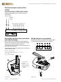
Electrical wiring for motorized fire
damper
Only a trained electrician is allowed to perform the elec-
trical wiring according to separate drawings and wiring
diagrams. Wiring diagram for fire damper actuator is
shown below.
Microswitch wiring for fuse mechanism
operated fire damper
The microswitch does not affect fire damper triggering, it
just indicates the position of the fire damper blade. The fire
damper closes when the thermal trip activates.
Status data from the microswitch can be provided from two
microswitches (open/close).
Proper functioning of the microswitch must be checked and
proper indication verified.
Electric specification:
Operating temperature -25 °C ... +70 °C
Imax = 0,1 A
Umax = 30 V (AC/DC)
1 Test button
2 Cover
3 Cable clamp
4 Microswitches
(under cover)
5 Handle
Wiring diagram for microswitch
Wiring digram shows the situation where damper blade is
in closed position and microswitch (0°) is activated.
Figure 12. Figure 13.
2
5
4
3
1
123456
2
1 2
0° 90°
3 4 5 6
AC 230 V
AC 24 V
DC 24 V

FläktGroup DC_9938GB 20210830_R3 Specifications are subject to alteration without notice.
Fire Damper ETPR - Instructions for Installation, Operation and Maintenance
11
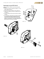
Replacing fuse part ETFF-99-01
NOTE! Safety gloves should be used when replacing the
fuse part.
1. Release the mechanism with the test button (1) – close
the fire damper. Figure 14.
2. Remove the fuse part mounting screw (6). Figure 15.
3. Holding the test button, pull out the complete fuse part
(7). Figure 16.
4. Correctly install the new fuse part and fasten it with the
screw (6).
5. Test the function of the product and reset the fire damp-
er. Turn the handle towards the OPEN position until
the mechanism clicks and the blade locks into OPEN
position. To test the operation of the fuse mechanism,
push the red test button (1) – the spring should close the
blade. Beware of the turning reset handle!
Figure 14.
Figure 15.
Figure 16.
1
6
6
7
6

WWW.FLAKTGROUP.COM ETPR 9938
» Learn more on www.flaktgroup.com
or contact one of our offices
FG_DC_9938GB_ETPR_IN-MA_20210830_R3 © Copyright 2021 FläktGroup
FläktGroup is the European market leader for smart and energy efficient Indoor Air
and Critical Air solutions to support every application area. We offer our customers
innovative technologies, high quality and outstanding performance supported by more
than a century of accumulated industry experience. The widest product range in
the market, and strong market presence in 65 countries worldwide, guarantee
that we are always by your side, ready to deliver Excellence in Solutions.
PRODUCT FUNCTIONS BY FLÄKTGROUP
Air Treatment | Air Movement | Air Diffusion | Air Distribution | Air Filtration
Air Management & ATD’s | Air Conditioning & Heating | Controls | Service
-
 1
1
-
 2
2
-
 3
3
-
 4
4
-
 5
5
-
 6
6
-
 7
7
-
 8
8
-
 9
9
-
 10
10
-
 11
11
-
 12
12


Ask a question and I''ll find the answer in the document
Finding information in a document is now easier with AI
Related papers
-
FläktGroup ETCE/ETCS Installation guide
-
-
-
-
-
-
-
-
-
Other documents
-
Ortech FIRE DAMPER-ODC User manual
-
Trox FKRS-EU Installation guide
-
 SystemAir FDR-3G-200-H0-OF User manual
-
-
-
Greenheck Fan OFD-XXX User manual
-
-
Greenheck 461335 Corridor Ceiling Dampers Operating instructions
-
-
