Page is loading ...

IFD2411-1
IFD2411-2
IFD2411-3
IFD2411-6
Quick Manual
confocalDT 2411
EtherCAT

MICRO-EPSILON
MESSTECHNIK
GmbH & Co. KG
Koenigbacher Str. 15
94496 Ortenburg / Germany
Tel. +49 (0) 8542 / 168-0
Fax +49 (0) 8542 / 168-90
e-mail [email protected]
www.micro-epsilon.com
You can find more information about the measuring system
in the operating instructions. They are available online at:
www.micro-epsilon.de/download/manuals/man--
confocalDT-2410-2411-2415--en.pdf
Contents
General ......................................................................................3
Symbols Used ............................................................................... 3
Warnings ....................................................................................... 3
Intended Use ................................................................................. 4
Proper Environment ...................................................................... 4
Glossary ........................................................................................ 4
Mechanical Fastening Sensor ..................................................5
Preliminary Remarks ..................................................................... 5
Circumferential Clamping ............................................................. 5
Mechanical Fastening Controller .................................................. 6
Start of Measuring Range ............................................................. 6
Electrical Connections .................................................................. 7
Supply Voltage .............................................................................. 8
Synchronization, Trigger ............................................................... 8
RS422 Connection with USB Converter IF2001/USB .................. 9
Sensor LEDs ..............................................................................9
Multifunction Button .................................................................. 10
Sensor Cable, Optical Fiber ...................................................11
Initial Operation .......................................................................12
Switch between EtherCAT and Ethernet Setup Mode ............... 13
Access via Web Interface ............................................................ 14
Positioning the Target ................................................................. 15
Presets, Setups, Measurement Configuration, Signal Quality ... 16
Checking the Video Signal, Peak Selection ............................... 18
Distance Measurement with Website Display ........................19
One-Sided Thickness Measurement, Transparent Target .....21
Preset Selection .......................................................................... 21
Material Selection ........................................................................ 21
Video Signal ................................................................................ 22
Measurement Chart for Thickness Measurement ...................... 23
Switch between Ethernet Setup Mode and EtherCAT ...........24
EtherCAT .................................................................................. 25
Preliminary Remarks ................................................................... 25
Parameter Setting via EtherCAT ................................................. 25
Saving the Settings, Continuing EtherCAT Mode ...................... 26
Service, Repair ........................................................................27
Disclaimer ................................................................................27
Decommissioning, Disposal ...................................................28
EtherCAT® is registered trademark
and patented technology, licensed by
Beckhoff Automation GmbH, Germany.

Page 3
General
confocalDT 2411
General
Symbols Used
The following symbols are used in this document:
Indicates a hazardous situation which, if not avoided, may result in minor or moderate injury.
Indicates a situation that may result in property damage if not avoided.
Indicates a user action.
iIndicates a tip for users.
Measurement
Indicates hardware or a software button/menu.
Warnings
Connect the power supply and the display/output device according to the safety regulations for
electrical equipment.
> Risk of injury, damage to or destruction of the controller
When all interfaces are used, the controller heats up to more than 50 °C.
> Risk of injury
Avoid shocks and impacts to the sensor and controller.
> Damage to or destruction of the sensor and/or controller
The supply voltage must not exceed the specified limits.
> Damage to or destruction of the sensor and/or controller
Protect the cables against damage.
> Failure of the measuring device

Page 4
General
confocalDT 2411
Intended Use
- The measuring system is designed for use in an industrial environment. It is used for
displacement, distance, movement and thickness measurement,
measuring the position of parts or machine components
- The measuring system must only be operated within the limits specified in the technical data.
The measuring system must only be used in such a way that no persons are endangered or machines are dam-
aged in the event of malfunction or total failure of the controller.
Take additional precautions for safety and damage prevention in case of safety-related applications.
Proper Environment
Sensor Controller
Protection class IP64, front side IP40
Operating temperature range +5 ... +70 °C +5 ... +50 °C
Temperature range (storage) -20 ... +70 °C
Humidity 5 ... 95 % (non-condensing)
Ambient pressure Atmospheric pressure
Shock (DIN-EN 60068-2-27) 15 g / 6 ms in XY-axis, 1000 shocks each
Vibration (DIN-EN 60068-2-6) 2 g / 20 ... 500 Hz in XY-axis, 10 cycles each
Glossary
SMR Start of measuring range MMR Mid of measuring range
MR Measuring range EMR End of measuring range
Minimum target thickness see Technical Data, Operating Instructions
Maximum target thickness Sensor measuring range x Refractive index of target

Page 5
Mechanical Fastening Sensor
confocalDT 2411
Mechanical Fastening Sensor
Preliminary Remarks
The optical sensors operate in the nanometer range.
Observe the maximum tilt angle between sensor and
target.
i
Ensure careful handling during installation and
operation!
Circumferential Clamping
Use an installation bracket MA240x to mount
IFS2404-1 / 3 / 6 sensors.
Mounting
ring
Size A Size B Size C
C
B
A
MA2400-27 ø27 ø46 19.75
(.78)
Mounting ring MA2400-27
20 (.79)
10 (.39)
30 (1.18)
13 (.51)
10 (.39)
30 (1.18)
23 (.91)
7 (.28)
M5
Mounting block MA240x
Use an installation bracket MA2404-12 to mount
IFS2404-2 sensors.
4.4
2
M4
M4
8
16 (.63)
16 (.63)
9
+0.018
0
9
18
0.5
10
ø4.5
34 (1.34)
28
ø12.1
ø8
Montageblock MA2404-12

Page 6
Mechanical Fastening Sensor
confocalDT 2411
Mechanical Fastening Controller
59 (2.32)
109 (4.29)
66 (2.60)
appr. 126
5
56 (2.20)
Optical fiber
C2401-x
Bending radius
min. R30
SC2415-x/OE
I/O interfave cable
Bending radius min. R35
appr. 142 (5.59)
Power
Sensor
I/O Interface
IE Interface
Sync/Trig
confocal DT
Intensity Multifunction
Range
RUN/SF/MS
ERR/BF/NS
The IFC2411 controller can be
mounted, e.g., in a control cabinet
using a top-hat rail TH 35 according
to DIN EN 60715.
i When attaching the controller,
ensure that no connections,
operating or display elements
are covered.
Dimensional drawing IFC2411, dimension in mm (inch)
Start of Measuring Range
A start of measuring range (SMR) between the sensor and the target must be kept.
Sensor SMR End of measuring range
Target
Start of measuring range (SMR), the
shortest distance between the front
surface of the sensor and the target

Page 7
Mechanical Fastening Sensor
confocalDT 2411
Electrical Connections
Switch / PC / Ethernet
SPS
PC
Intensity Multifunction
1 Power 3
Sensor
1 Sync/Trig 5Interface
Ind. Ethernet
confocal DT
Range
RUN/SF/MS
ERR/BF/NS
USB
SC2415-x/OE
C2401-x
Sensor
Analog output
Encoder
A, B
IF2001/USB
RS422/USB converter
(optional)
Patch cable
Cat5E
PS 2020
Power supply
(optional)
Characteristics SC2415-x/OE signal line:
- Analog output
- RS422
- Encoder
The SC2415-x/OE cable is not included in delivery.
17-pin male connector
controller
SC2415-x/OE
Signal Pin Wire color
Analog output 1 white, internal
Analog GND 2 black 1
Data Tx- 3 black
Data Tx+ 13 purple
n.c. 5 red
n.c. 14 blue
Encoder 1B+ 8 grey
Encoder 1B- 15 pink
Encoder 1Ref+ 9 green
Encoder 1Ref- 16 yellow
Data Rx+ 10 brown
Data Rx- 11 white
Encoder 1A- 12 red/blue
Encoder 1A+ 17 grey/pink
Pin assignment SC2415-x/OEY
7
9
15
16
6
5
8
12
1 11 10
13 4 14
2
3
17
The GND connections are
not electrically separated.
17-pin controller male
connector, pin side
1) Analog output in shielded
cable area

Page 8
Mechanical Fastening Sensor
confocalDT 2411
Supply Voltage
Nominal value: 24 V DC (20 ... 28 V, P < 7 W)
1 Power 3
1 Sync/Trig 5
1
2
20 ...
28 VDC
Controller
3-pin pluggable
screw terminal
Power
supply
1V+
2 GND
3 Screen
Voltage supply only for measuring devices, not to be
used for drives or similar sources of impulse interference
at the same time. MICRO-EPSILON recommends using
an optional available power supply unit PS2020 for the
sensor.
Only turn on the power supply after wiring has been
completed.
Connect the inputs Pin 1 and Pin 2 at the sensor
with a 24V power supply.
Synchronization, Trigger
Interconnected all GND, if the controllers are not
supplied from a common power supply.
1 Sync/Trig 5
Trigger
Synch.
Controller
5-pol pluggable
screw terminal
Signal Level
1 Sync + RS422
2 Sync - RS422
3 Kabel shield
4 Trig TTL
5 GND
Star- or Cascaded synchronization
Connect Pins 1 and 2 of controller 1 (master) with
the correct polarity to Pins 1 and 2 of controller 2
(slave) to controller n, in order to synchronize two
or more controllers.
Triggering
Connect the pins 4 and 5 with a trigger source
(master).

Page 9
Sensor LEDs
confocalDT 2411
RS422 Connection with USB Converter IF2001/USB
In addition to Industrial Ethernet, the controller also supports serial communication via RS422. Serial communication
is possible with PC2415-x/OE cables. The PC2415-x/OE cable and the IF2001/USB RS422-to-USB converter are an
optional accessory.
Properties: Differential signals according to EIA-422,
galvanically connected to the supply voltage.
Use a shielded cable with twisted wires.
Cable length less than 30 m.
Connect the ground connections.
Controller
17-pin connector
Signal SC2415-x/OE IF2001/USB
3 TX - black RX -
13 TX + purple RX +
10 RX + brown TX +
11 RX - white TX -
Housing Shield Cable shield ---
Sensor LEDs
RUN green Off Slave is in the "Init" status
RUN/SF/MS
ERR/BF/NS
green flashes evenly Slave is in the "Pre-Operational" status
green flashes briefly Slave is in the "Safe-Operational" status
green flashes quickly Slave is in the "initialization" or "bootstrap" status
green lights up Slave is in the "Operational" status
ERR red Off No error
red flashes evenly Invalid configuration
red flashes briefly Unwanted status change
red flashes twice Timeout of the Application watchdog
red flickers Boot error
red lights up Timeout of the PDI watchdog

Page 10
Sensor LEDs
confocalDT 2411
LED Color Status Meaning
Intensity
Range
Intensity
red flashes Dark signal acquisition in progress
red lights up Signal saturated
yellow lights up Signal too low
green lights up Signal OK
Range
red flashes Dark signal acquisition in progress
red lights up No target present, outside of measuring range
yellow lights up Target close to mid of measuring range
green lights up Measuring object within the measuring range
Multifunction Button
The
Multifunction
button is assigned multiple functions. As default, the button is assigned the dark reference
function.
Intensity Multifunction
Range
RUN/SF/MS
ERR/BF/NS
Function
Dark reference Starts dark referencing
Factory setting Reset the device and measurement settings to factory set-
tings.
The selected function is indicated by the flashing/illuminated
Range
and
Intensity
LEDs.
0 10 sec2 sec Time
Factory
setting
Dark reference
Multifunction
button actuation time
The
Multifunction
button is not assigned a key lock in
the factory. Optionally, you can deactivate or lock the
Mul-
tifunction
button, see the operating instructions for
the controller. With the
Multifunction
key you can also
change the operation mode. For details, refer to section
Initial Operation
or
Switch between EtherCAT
and Ethernet Setup Mode
.

Page 11
Sensor Cable, Optical Fiber
confocalDT 2411
Sensor Cable, Optical Fiber
Sensor and controller are connected through an optical
fiber.
- Do not shorten or lengthen the optical fibers.
- Do not pull or hold the sensor on the optical fiber.
Do not kink the sensor
cable.
Please do neither
squeeze the sensor
cable nor fix it by using
cable ties.
Please do not grind the
sensor cable over sharp
corners.
Do not pull the sensor
cable.
Cleaning of the connectors requires the corresponding
know-how.
Basic Rules
Avoid
- any contamination of the connector, e. g. dust
- any mechanical stress of the fiber
- strong bending of the fiber
Please never underrun the allowed bending radius.
R
Fixed:
R = 30 mm or more
Flexible:
R = 40 mm or more
Socket groove on the sensor
(left) and guiding peg of an FC
sensor plug (right)
Fiber optic and sensor
i Note the orienta-
tion of the socket
and the guiding
peg.

Page 12
Initial Operation
confocalDT 2411
Initial Operation
i The measuring system is ready for operation approx. 3 s after applying the supply voltage.
To ensure precise measurements, let the measuring system warm up for about 50 minutes.
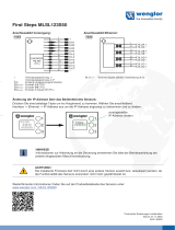
The controller starts in the last stored operating mode. Default is EtherCAT.
Alternative communication with the sensor
Ethernet-Setup-Mode RS422 Communication Ethernet over EtherCAT (EoE)
- Programming via web interface,
- no EtherCAT
- Programming via web interface;
- programming on command level e.g. with
Telnet,
- no parallel output of measurement data via
EtherCAT and RS422 possible
- Programming via web interface;
- programming on command level
e.g. with Telnet,
- Parallel programming and mea-
surement
Switch to the Ethernet setup mode.
Details can be found in section
Switch
between EtherCAT and Ethernet
Setup Mode
.
Connect the sensor and the PC
with a LAN cable.
Start your web browser and
type the default IP address
169.254.168.150 of the sensor into
the address bar.
Connect the sensor, e.g. via an IF2001/
USB RS422 converter from Micro-Epsilon
via USB to a PC.
Start the
sensorTOOL
program.
Download at https://www.micro-epsilon.de/
download/software/sensorTOOL.exe.
Click the
Sensor
button.
The program will now search for connected
sensors.
Select a desired sensor. Click the
Open
Website
button.
Enable the EoE in your PLC
software.
Assign each a virtual MAC ad-
dress and an IP address to the
controller with your EtherCAT
master.
Saved settings remain in the sensor remanently across interfaces

Page 13
Initial Operation
confocalDT 2411
Switch between EtherCAT and Ethernet Setup Mode
The controller starts in the last stored operating mode. Factory setting is EtherCAT. Access via Ethernet is possible in
the Ethernet setup mode.
Press and hold the
Multifunction
button on the controller before switching on the power supply on the sen-
sor. Release the button again as soon as the
Intensity
LED flashes yellow. Press the button again for approx.
10 to 15 seconds until the
Intensity
LED flashes red.
Within the time t2 ... t3, the red flashing with 8 Hz starts after 10 seconds. The key must be released again after 15
seconds at the latest. When the
Multifunction
key is released at the latest at time t3, the
Intensity
LED starts to
flash yellow at 8 Hz.
Intensity LED
Firmware installation or
EtherCAT/Ethernet switch
Multi-
function key
Supply
voltage
red
yellow, appr. 8 Hzred, appr. 8 Hzyellow flashing appr. 1 Hz yellow green yellow
t0t1t3
t2
10 ... 15 sec
t4
Ethernet Setup Mode
0
1
0
1
Flowchart for starting a controller in Ethernet setup mode
After completion of the firmware installation/switch, the controller reboots at time t4 .
t0: Supply voltage is applied
t1: The
Intensity
LED starts flashing yellow, the
Multifunction
button can be released
t2: Within 15 sec. (t2 - t1), press
Multifunction
button again and hold for further 10 ... 15 sec. (t3 - t2)
t3... t4: Switches from EtherCAT to Ethernet Setup Mode, duration max. 1 min.
t4: Controller starts in Ethernet setup mode, the
Intensity
LED lights up briefly at intervals of approx. 1 sec.

Page 14
Initial Operation
confocalDT 2411
Access via Web Interface
Start the web interface of the controller, see section
Initial Operation.
Interactive web pages you can use to configure the
controller are now displayed in the web browser. The
controller is active and supplies measurement values.
The web interface does not guarantee real-time mea-
surements. The currently running measurement can
be controlled using the function buttons in the
Chart
type
section.
First page after web interface has been accessed in
Ethernet mode
For configuration, you can switch between the video sig-
nal and a display of the measured values over time. The
appearance of the websites depends on the functions.
Dynamic help texts with excerpts from the operating in-
structions supports you during controller configuration.
i Depending on the selected measuring rate and the
PC used, measured values may be reduced in the
display. That is, not all measured values are trans-
mitted to the web interface for display and saving.
The horizontal navigation includes the functions below:
-
Home
. The web interface automatically starts in this
view with Measurement Chart,
Measurement con-
figuration
and
Signal quality
.
-
Settings
. Sensor parameters configuration such as
triggering, measuring rate and zero setting/mastering.
-
Measurement chart
. Measurement chart or video
signal display.
-
Info
. Includes information about the controller, such
as measuring range, serial number and software
status.

Page 15
Initial Operation
confocalDT 2411
The vertical navigation is contextual to the selection in the horizontal navigation
and contains the following functions for the
Home
menu:
- The
Search settings
function permits time-saving access to functions
and parameters.
-
Measurement configuration.
Allows a selection of predefined measure-
ment settings.
-
Signal quality
By mouse click it is possible to switch between three pre-
defined basic settings for the measuring rate and the averaging.
Positioning the Target
Position the target as centrally as possible within the measuring range.
100 %
50
0SMR MMR EMR
Displacement
Output signal
analog / digital
SMR Measuring range (MR)
Target
Sensor
Range
LED
intensity
range
Range LED
Red No target present or target
outside of measuring range
yellow Target close to mid of measur-
ing range
green Measuring object within the
measuring range
The
Range
LED on the front of the controller indicates the
position of the target relative to the sensor.

Page 16
Initial Operation
confocalDT 2411
Presets, Setups, Measurement Configuration, Signal Quality
Definition
- Preset: Manufacturer-specific program with settings for frequent measurement tasks; cannot be overwritten
- Setup: User-specific program with relevant settings for a measurement task
- Initial setup at boot (controller start): a favorite can be selected from the setups, which is automatically activated at
controller start. If no favorite is determined from the setups, the controller activates the
Standard
preset at startup.
Upon delivery of the controller from the factory
- the presets
Standard, Standard shiny,
Multisurface
and
One-sided thickness mea-
surement
are possible
- for the IFD2415 sensor, the presets
Multilayer air
gap
and
Multilayer composite material
are
available.
- no setup is available.
You can select a preset in the tab
Home > Measurement configuration
You can select a setup in the tab
Home > Measurement configuration
or
Settings
in the
System settings > Load & save
menu
A setup can be stored permanently in the controller.

Page 17
Initial Operation
confocalDT 2411
For all presets, the measurement task can be individually adapted via the
Signal quality
slider. Reducing the
measuring rate increases the exposure time for the line and thus improves the measurement quality.
Measuring rate Averaging 1Description
0.2 kHz Static
Moving, 128 values
Three predefined basic settings (Static, Balanced
and Dynamic); a change via mouse click is immedi-
ately visible in the diagram and the system configu-
ration.
i If the controller starts up with a user-defined
measurement setting (setup), the signal quality
cannot be changed.
1 kHz Balanced
Moving, 16 values
5 kHz Dynamic
Moving, 4 values
Presets allow a quick start into the individual measurement task. Basic features such as peak and material selection
and the calculation functions are already set in the presets to match the target surface.
Distance measurement, e.g., for ceramic material,
non-transparent plastics. Highest peak, averaging,
distance calculation.
i After programming, save all
settings permanently to a
parameter set so that they
will be available again the
next time you switch on the
controller. To do this, use
the
Save settings
but-
ton.
Distance measurement, e.g., for metal, polished
surfaces. Highest peak, Median over 5 values,
distance calculation.
Distance measurement, e.g., for PCBs, hybrid
materials. Highest peak, Median over 9 values,
distance calculation.
One-sided thickness measurement, e.g., for glass,
BK7 material. First and second peak, averaging,
thickness calculation
1) Values apply to the
Standard
and
One-sided thickness measurement
presets.

Page 18
Initial Operation
confocalDT 2411
Checking the Video Signal, Peak Selection
The video signal shows the determined reflections at the measuring object as a raw signal. The peaks are counted
starting at the start of the measuring range toward the end of the measuring range. The corresponding measured
value is marked by a vertical line (peak marking).
Go to the
Measurement chart
menu. Display the video signal with
Video
. Adjust the settings for the exposure
mode and measuring rate parameters.
1. Peak 2. Peak 3. Peak n. Peak The selection of peaks dictates which
region in the signal is used for the distance
or thickness measurement. For a measur-
ing object consisting of several transparent
layers, use the refractive index correction to
compensate for the distance measurement
errors caused by optical factors, see oper-
ating instructions.
Video signal of transparent measuring
object with four peaks (optical boundary
areas) in the measuring range
1 measurement first peak / highest peak / last peak The
Standard, Standard shiny
and
Multisurface
presets use the highest
peak.
The preset
One-sided thickness mea-
surement
uses the 1. and 2. peak for the
calculation of the measured value.
Go to the
Data Recording > Set-
tings > Peak selection
menu to
select a different peak.
2 measurement
values
first and second peak / first and last peak /
second to last and last peak /
highest and second highest peak
Options for peak selection

Page 19
Distance Measurement with Website Display
confocalDT 2411
Distance Measurement with Website Display
Align the sensor perpendicularly to the object to be measured.
Then, move the sensor (or the target) closer and closer to the start of the measuring range of the relevant sensor.
As soon as the object is within the measuring field of the sensor, the controller’s
Range
LED lights up (green or yel-
low). Alternatively, you can watch the video signal.
2
1
3
4
5
6
2
8
7
Measurement
(distance measurement) web page

Page 20
Distance Measurement with Website Display
confocalDT 2411
1
Stop
pauses the chart; you can still use the data selection and zoom functions.
Save
opens a Windows selection
dialog for the file name and storage location to save the last 10,000 values in a CSV file (separation using semico-
lon).
2 All changes only become effective when you click on the
Save settings
button.
3 In the left-hand window, the signals to be displayed can be switched on or off during or after the measurement. In-
active curves are grayed out and can be added by clicking on the check mark. The changes become effective when
you save the settings.
You can show or hide the individual signals using the eye symbols . The calculation continues in the background.
01SHUTTER: exposure time
01xINTENSITY: Signal quality of the underlying peak in the video signal
01DIST: Distance signal curve over time
4 To scale the axis in the graph for the measured values (y-axis), you can use
Auto
(= automatic scaling) or
Manual
(= manual scaling).
5 The current values for distance, exposure time, current measuring rate and time stamp are shown in the text boxes
above the graph. Errors are also displayed.
6 Mouseover function. When the chart has been stopped and you move the mouse over the graph, points on the
curve are marked with a circle and the associated values are displayed in the text boxes above the graph. The inten-
sity bars are also updated.
7 The peak intensity is displayed as a bar chart.
8 Scaling the x-axis: During an ongoing measurement, you can use the left-hand slider to enlarge the entire signal
(zoom). The time range can also be defined using an input field under the time axis. When the chart has been
stopped, the right-hand slider can also be used. You can also move the zoom window with the mouse in the center
of the zoom window (four-sided arrow).
/