Page is loading ...

GENERIC BANK BRANCH LARGE QUICK START GUIDE
LT-1458 © 2019 Digital Monitoring Products, Inc. 19312
2. Reference Information
Caution: Remove all transformer and battery power from the panel
before installing or connecting any modules, cards, or wires.
System Grounding
The XR550Series panel Terminal 4can be connected to earth ground
using 14gauge or larger wire. Connect to a cold water pipe, ground rod,
or building ground when available. Connection to an electrical ground
or conduit can also be used. Gas pipes or sprinkler pipes should not be
used. A ground connection is not required to provide normal system
operation.
System Wiring
All wiring must be in accordance with NEC, ANSI, and NFPA 70. Use
non‑shielded 22AWG wire for short wire runs from the panel. Use
non‑shielded 18AWG wire for longer wire runs from the panel. Refer to
the LX‑Bus/Keypad Bus Wiring Note (LT‑2031). It is recommended that
strain reliefs be used in all locations where wires exit an enclosure and
conduit is not used.
DMP recommends using 18or 22–gauge unshielded wire for all keypad
circuits. Do not use twisted pair or shielded wire for Keypad Bus data
circuits. To maintain auxiliary power when using 22–gauge wire, do not
exceed 500feet. When using 18–gauge wire, do not exceed 1,000feet.
For longer runs, install an additional power supply or repeater.
Ensure all connections from the panel enclosure to the battery enclosure
and from the power supply enclosure to the battery enclosure are in
3/4” conduit. DMP recommends using strain reliefs in all locations where
wires exit an enclosure and conduit is not used.
Reference Documents
Refer to the documents listed below as needed.
• XR150/XR550Series Installation Guide (LT‑1233)
• XR150/XR550Series Programming Guide (LT‑1232)
• 7000Series Keypad Installation Guide (LT‑0883)
• 263LTE Installation Guide (LT‑1592)
• 1100XH Wireless Receiver Installation Guide (LT‑0970)
• 861Power Distribution Installation Guide (LT‑0795)
• 714‑8/714‑16Installation Guide (LT‑0401)
• 505‑12 Installation Guide (LT‑0453)
• 1142 Series Two‑Button Transmitter Installation Guide (LT‑0700)
• Any documentation included with the system components
Current Draw
Combined current draw from XR550Auxiliary (Terminal 7), Smoke
(Terminal 11), X‑Bus, and LX‑Bus must not exceed 625mA in order to
support 80hours of standby operation. Ensure the total current draw of
optional devices does not exceed the 625mA of power supplied by the
panel. A separate power supply is needed to support devices beyond
625mA.
3. Mount the Enclosures
Prior to mounting and as needed, open any enclosure knockouts. Mount
the 352P‑G Extra Large Enclosure with the pre‑mounted panel in a secure,
dry place to protect the components from damage. It is not necessary to
remove the pre‑mounted components when installing the enclosure. Make
sure all wiring in the XR550DE Enclosure is routed neatly and securely to
keep the wiring o the panel and power supplies.
Mount the 352S Battery enclosure adjacent and to the right of the
XR550panel enclosure in a secure, dry place to protect the batteries from
damage due to tampering or the elements. Use the two supplied 3/4” X 2”
conduit pieces to connect the panel and battery enclosures through the
side knockouts as shown in Figure 1.
Generic Bank Branch System Information
Before installing any equipment, complete the following section.
Account Number _____________________________________________
Address ____________________________________________________
Phone Number _______________________________________________
DHCP ______________________________________________________
Control Panel IP Address _______________________________________
Gateway Address _____________________________________________
Subnet Mask _________________________________________________
Programming Port ____________________________________________
Installation Date ______________________________________________
Installer Name _______________________________________________
1. System Components—Lev. A (KIT‑XXX‑XR550BRANCH)
The system package includes the following components:
• One 352P‑G101Extra Large Enclosure w/Mounting Plate:
◦Two 100VA Transformers
• One XR550DEPCB with built‑in 128bit Encryption
• One 505‑12PCBPower Supply
• One 861Auxiliary Power Distribution and Bus Module
• Three 714‑16PCBZone Expanders
• One 263LTE‑V Cellular Communicator with Cable
• One 381‑12SMA Extension Cable (12’)
• One 386Antenna Mount Bracket
• One 352S Large Enclosure for 80Hour Standby Batteries
• One 7070 32‑Character LCD Keypad
• One additional 7070 Keypad (optional)
• One 1100XH High Power Wireless Receiver
• Ten 1142Two‑button Holdup Transmitters
• One 431Output Harness
• Two 305Plug‑in Output Relay
• Four 307‑S Tamper Switches
• Four 306 Tamper Harnesses
• One 357‑10Black Cat 5e Cable (10’)
• One AC Power Cord with Right Angle Plug (12’)
• One PSD100Vault Audio Detector
• Six 366 12VDC 18Ah Batteries
• Two 318EXT Battery Harness Extensions
• Three 318Dual Battery Harnesses
• Five 318R Dual Battery Harnesses with Ring Terminals
• Three 572Annunciator Plates with LED
• One SX360Z Optex Extra Long Range 360Motion Detector
• Two CDX‑DAMDual Tech Motion Detectors
• Two CX‑702Optex Dual Motion Detectors (70’ x 70’ or 80’ x 6’)
• One 330Programming Cable
• Conduit Accessories
4. Install the 305Relays and 431Harness
Install the two 305Plug‑in Output Relays into XR550Output 1and Output
2. The relays only operate when installed with the coil end down. Check
the panel wiring diagram in this guide as needed. Carefully align the relay
pins and press the relay into the socket. Plug the 431Output Harness into
panel Out1Out2Header between Output 1and Output 2. The 431output
harness is not connected to any devices during this installation. For more
information, refer to Figure1.
5. Install the 714‑16PCBExpanders
Note: For detailed mounting location information, refer to Figure1.
1. Mount the 714‑16PCBbeneath the panel in the panel enclosure.
2. Set the KPD LX on the zone expander to LX. Set the rotary switches
to 0, 0to enable LX Bus zones 500through 515 and connect the
714‑16to the XR550LX500header.
3. Connect additional 714‑16Zone Expanders as needed.
Install any additional zone expanders connected to the XR550enclosure
with a conduit nipple whenever possible. They may also be mounted in the
field as required to replace an existing zone expander.
Set the KPD LX jumper on the optional zone expander to LX. Set the rotary
switches to 1, 6to enable LX‑Bus zones 516through 531. If more than one
zone expander is installed, refer to the 714‑16Installation Guide (LT‑0401)
and set subsequent rotary switches as needed. For more information, refer
to Figure1.
6. Mount the Model 307‑S Tamper Switches
Use 22AWG wire as needed to wire the tamper switches. Attach the Model
307Tamper Switch in the lower right side of the panel enclosure with
the button protruding past the enclosure edge. Connect the 307Tamper
Switches to XR550panel TAMPER header with the included 306 harnesses.
7. Mount the 1100XH Wireless Receiver
Choose an optimal location to mount the receiver. Ensure the 1100XH
is centrally located between the 1100Series transmitters used in the
installation. Be sure to mount the receiver away from large metal
objects and equipment enclosures because it may impair the receiver’s
performance. Do not mount above T‑Bar ceilings. Do not use shielded wire
between the panel and receiver. The 1100XH can be mounted up to 500ft
(150m) from the panel using 22AWG or 1000ft (300m) using 18AWG.
1. Remove the cover from the plastic housing.
2. Secure the receiver to the surface, ensuring the wall tamper switch
makes proper contact with the wall.
3. Connect the PANEL header on the 1100XH to the XR150/XR550panel
XBUS header.
8. Install the 263LTE‑V Cellular Communicator
Caution: Before installing the 263LTE‑V, ensure power to the panel is
disconnected. Failure to do so may result in equipment damage.
For installation details, refer to Figure1.
1. Record the device SIM for programming later.
2. Insert the included stando into the XR550Series panel stando
hole.
3. Secure the 263LTE‑V on the 12‑pin Cell Module connector.
4. Align the 263LTE‑V stando hole with the stando already placed in
the panel and snap it into place.

2 Digital Monitoring Products Generic Bank Branch Large Quick Start Guide (KIT-XXX-XL550BRANCH)
9. Connect the 263LTE‑V Antenna
1. Remove one of the available 1/2” knockouts from the top of the
enclosure. If no knockouts are available, drill a 1/2” hole through the
top of the enclosure. The antenna must be mounted vertically.
2. Connect the 381‑2coax cable to the 263LTE SMA connector.
3. Place one washer on the 381‑2SMA connector and push the threaded
end through an open enclosure knockout.
4. Place the second washer on the threaded end extending through the
knockout and thread a nut onto the connector.
5. Attach the 381‑12SMA Extension Cable to the SMA connector on the
top of the panel enclosure.
6. Mount the 386Antenna Mount Bracket where instructed by the
customer.
7. Run the 381‑12cable to the bracket. Place one washer on the
381‑2SMA connector and push the threaded end through the
bracket.
8. Place a washer on the threaded end extending through the bracket
and thread a nut onto the connector.
9. Attach the 383Antenna to the SMA connector on top of the
386bracket.
10. Connect the Ethernet Cable
Using the Cat 5e network cable (357‑10), plug one end into the XR550
panel Ethernet connector. Run the other end through a strain relief and
plug the network cable into the customer‑supplied network connector.
11. Connecting the 861Power Distribution and Bus Module
For wiring details, refer to Figure1.
1. Mount the 861 to the left of the XR550 in the panel enclosure as
shown in Figure 1 with the three included plastic standos and
Phillips head screws.
2. Using the 4‑wire harness cable, connect the programming header of
the XR550to the BUS‑A on the 861.
3. Connect a wire from the 861BLK GND IN terminal to panel Terminal
10.
4. Connect another wire from the 861BLK GND IN to 505‑12 DC
negative.
5. Connect a wire from the 861RED PWR IN terminal to 505‑12 DC
positive.
6. Use the 861RED POWER OUT and BLACK GROUND OUT terminals
to provide power for all output devices (motions, seismic, ATMs).
12. Install the 7070 Keypads
Use the included wiring harness to connect the DMP 7070 Keypads to
the 861. Observe wire colors when connecting and do not use shielded
wire. You can install a maximum of 16addressable supervised devices on
the keypad bus. Connect each keypad to the 861BUS‑A header. For more
information, refer to Figure1.
13. Wire the Zones
Zones 1‑10are located directly on the XR550panel. Wire the zones as
required. Zones 1through 8use 1K Ohm EOL resistors and Zones 9and
10use 3.3K EOL resistors.
Keypad Bus expansion zones are numbered in groups of four
corresponding to the address. Example: address 1is zones 11‑14and address
16is zones 161‑164. There are a maximum of 64zones possible on the
Keypad Bus. All keypad zones terminate with a 1k Ohm EOL resistor.
When using the LX500header, 100zones numbered 500 ‑ 599are
available.
Panel Zone # Device Type
1 Reserved
2 Reserved
3 Reserved
4 Reserved
5 Power Supply Low Battery
6 Power Supply AC Fail
7 Unused
8 Unused
9 Reserved
10 Reserved
Table1: Zone Wiring
14. Connect the Motion Detectors
Connect each motion detector power to the pre‑wired 861Auxiliary Power
Distribution and Bus Module. Wire the motion detectors as NC (Normally
Closed). When activated, the motion detectors open the circuit. Refer to
the 861Detail drawing on the wiring diagram and the Zone Layout table for
zone information.
15. Connect the 572Panic LEDs
Connect the Red Panic LED wires to Terminal 5 (Bell). Connect the White
572Panic LED wires in parallel to XR550Terminal 6 (GND). Install a 1k Ohm
EOL resistor across the red and white wires of the last 572Panic LED. Refer
to Figure1.
16. Install 1142Holdup Transmitters
Before mounting the1142, confirm communication with the panel using
the survey LED. For more information, refer to the1142Installation Guide
(LT‑0700).
1. Insert a small flat‑head screwdriver into the access slot on either end
of the 1142housing and gently turn the screwdriver to separate the
two parts.
2. Place the base with the LED cutout toward the front edge of the
counter and use the two supplied Phillips head screws to mount the
base.
3. Align the top housing and LED with the base cut‑out and snap the
two halves together.
17. Wire the Batteries
DMP requires each battery be separated by a PTC in the battery harness
wiring to protect each battery from a reversal or short within the circuit.
For wiring details, refer to Figure1.
Caution: Observe polarity when connecting batteries. Wire all batteries
in parallel. Ensure all battery harness connectors are fully inserted to
prevent shorting.
Wire Batteries to the Panel
1. In the panel enclosure, connect the 14” Black battery wire to panel
Terminal 4. Connect the 14” Red battery wire to panel Terminal 3.
2. Plug the 14” Red and Black battery wires onto one 318EXT harness.
The 318EXT harness passes through the lower conduit easier if fed
from the 352S enclosure side.
3. In the battery enclosure, connect the 318EXT harness to one 318
harness. Connect the 318 harness to two 318R harnesses with ring
terminals.
4. Use the non‑PTC protected side of the first 318R harness and connect
to the first battery on the bottom shelf labeled Battery 5.
5. Connect the PTC protected side to the second battery on the bottom
shelf location labeled Battery 6.
6. Connect the second 318R harness PTC side to the second battery
located on the center shelf labeled Battery 4.
7. Cut the unconnected non PTC end of the second 318R harness and
insulate the cut ends. This end of the harness is not used.
8. Label each battery with the installation date.
Wire Batteries to the Power Supply
1. In the panel enclosure, connect the 14” Black battery wire to the
505‑12 BAT negative terminal.
2. Connect the 14” Red battery wire to the 505‑12 BAT positive
terminal.
3. Plug the 14” Red and Black battery wires onto one 318EXT Battery
Harness Extension. The 318EXT harness passes through the upper
conduit easier if fed from the 352S enclosure upper knockout.
4. In the battery enclosure, connect the 318EXT harness to one 318
Dual Battery Harness. Connect the 318 harness to two 318R dual
battery harnesses with ring terminals.
5. Use the non‑PTC protected side of the first 318R Dual Battery
Harness and connect to the first battery on the top shelf labeled
Battery 1.
6. Connect the PTC protected side to the second battery on the top
shelf location labeled Battery 2.
7. Connect the second 318R harness PTC side to the first battery
located on the center shelf labeled Battery 3.
8. Cut the unconnected non PTC end of the second 318R harness and
insulate the cut ends. This end of the harness is not used.
9. Label each battery with the installation date.
18. Complete Hardware Installation
Ensure all devices are properly addressed and all LX‑Bus and Keypad Bus
wiring is free of grounds, wire‑to‑wire shorts, and interference. Ensure all
field devices are properly terminated to the panel zone inputs.

Generic Bank Branch Large Quick Start Guide (KIT-XXX-XL550BRANCH) Digital Monitoring Products 3
19. Connect the Transformer and AC Power
Caution: Do not plug in the transformer until all devices are connected
to the panel and the batteries are wired. Never share the transformer
output with other equipment.
Run the transformer wires (18AWG minimum) into the panel enclosure
through a conduit. Wire the transformer as follows:
• Black wires from each transformer to Black AC cord wire
• White wires from each transformer to White AC cord wire
• Green/Yellow wire to the electrical ground
After all components are installed, plug the transformer into an unswitched
120VAC outlet.
20. Program the Keypads
Note: Address 1is reserved by the system for programming keypads.
1. On the keypad, hold down the back arrow and CMD keys for two
seconds to display SET BRIGHTNESS.
2. Enter 3577 (INST) and press CMD.
3. Press the left Select key under KPD OPT (Keypad Options).
4. Press the CMD key to display KEYPAD ADDRESS. Set the ATM
keypad address as listed in Table2:
5. Press the CMD key twice until DEFAULT KPD MSG displays.
6. Press any top row Select key. Enter the area name and panel account
number as the default keypad display. For example, PREMISE 3486.
7. At ARM PANIC KEYS, press the Select key under PN (Panic) to enable
the panic option. An asterisk displays next to enabled panic key
options.
8. Press CMD until STOP displays. Press the right Select key under STOP
to exit keypad programming.
9. If additional keypads are installed, repeat the steps above and refer to
Table2for keypad addresses.
Caution: Do not install included panic labels on keypads.
Keypad Address Location
1 RESERVED (Programming Keypad)
2 PREMISES
3VAULT
4 OTHER SAFES
5 BRANCH ATM
6 VENDOR ATM
7 DRIVE UP PREMISE
8 DRIVE UP VAULT
Table2: Keypad Addresses
21. Initialize the Panel and Configure Communication
After completing each of the following steps, press CMD to advance to the
next option. Program these settings according to the information recorded
in Generic Bank Branch System Information.
1. Reset the panel by placing a jumper over both RESET jumper pins. After a
few seconds, remove the jumper and place it on one pin for use later.
2. Enter6653 (PROG) at the panel keypad and go to INITIALIZATION.
3. At INIT ALL? select YES. At SURE? select YES to initialize the panel.
4. Enter 6653 (PROG), go to COMMUNICATION, then press any select key.
5. At the ACCOUNT NO prompt, press any select key and enter the
4‑digit account number.
6. Go to NETWORK OPTIONS and press any select key.
7. At DHCP, select NO.
8. At LOCAL IP ADDRESS, enter the Control Panel IP address.
9. At GATEWAY ADDRESS, enter the Gateway address.
10. At SUBNET MASK, enter the Subnet Mask address.
11. Go to REMOTE OPTIONS and press any select key.
12. At NETWORK PROG PORT enter the remote programming port.
13. Press CMD until STOP is displayed. Press any select key. This will save
the changes and will exit panel programming.
The panel is now ready for the remote connection to receive programming.
22. Zone Layout
For zones 1‑10, refer to Wire the Zones.
Note: Greyed‑out areas in the following tables indicate items not
included in this kit.
Zone # Name Zone # Name
500 Safe 1Door 534 Teller Line Motion
502 Safe 1Heat 535 Drive‑in Motion
503 Safe 1Seismic 536 ATM Room Motion
504 Safe 2Door 537 Cash Room Motion
506 Safe 2Heat 538 AHD Room Motion
507 Safe 2Door Seismic 539 Rear Entry Motion
516 AHD Door 540 Break Room Motion
517 AHD Heat 541 TeleData Room Motion
518 AHD Seismic 542 Electric Room Motion
519 AHD Head Tamper 543 Roof Hatch Latch
532 Front Entry Motion 544 Unused
533 Lobby Motion 545 Unused
Table3: Zones 500‑547 (714‑16 on LX500)
For Wincor 2350xe ATMs
Zone # Name Zone # Name
548 ATM 1Cash Chest 552 ATM 2Cash Chest
549 ATM 1Deposit Chest 553 ATM 2Deposit Chest
550 ATM 1Cash & Deposit
Heat
554 ATM 2Cash & Deposit
Heat
551 ATM 1Cash & Deposit
Seismic
555 ATM 2Cash & Deposit
Seismic
Table4: Zones 548‑555 (Pre‑installed 714 on Wincor ATM)
For All Other Models of ATMs
Zone # Name Zone # Name
548 ATM 1Chest 552 ATM 2Chest
549 ATM 1Heat 553 ATM 2Heat
550 ATM 1Seismic 554 ATM 2Seismic
551 Empty 555 Empty
Table5: Zones 548‑555 (Pre‑installed 714 on non‑Wincor ATM)
Zone # Name Zone # Name
600 Teller 1Holdup 623 Oce/Plat 4Holdup
601 Teller 2Holdup 624 Oce/Plat 5Holdup
602 Teller 3Holdup 625 Oce/Plat 6Holdup
603 Teller 4Holdup 626 Oce/Plat 7Holdup
604 Teller 5Holdup 627 Oce/Plat 8Holdup
605 Teller 6Holdup 628 Oce/Plat 9Holdup
606 Teller 7Holdup 629 Oce/Plat 10Holdup
607 Teller 8Holdup 630 Drive‑in 1Holdup
608 Teller 9Holdup 631 Drive‑in 2Holdup
609 Teller 10Holdup 632 Drive‑in 3Holdup
610 Teller 11Holdup 633 Drive‑in 4Holdup
611 Teller 12Holdup 635 CRM Holdup
620 Oce/Plat 1Holdup 636 Cash Room Holdup
621 Oce/Plat 2Holdup 639 Other Holdup
622 Oce/Plat 3Holdup
Table6: Zones 600‑639 (1100XH Wireless Receiver)
23. Download Programming
Call the central station to confirm that network communication is
established with the panel. Provide the cellular SIM and any pertinent zone
information.
24. Finalize the Installation
Refer to customer instructions for testing the system, finalizing the
installation, and receiving document sign os.
Test Communication Status
1. On the keypad, enter the Diagnostics Menu (DIAG).
2. Press CMD until COMM STATUS displays, then press any Select
Key.
3. At PATH, enter the path number.
4. Repeat the steps for each of the communication paths.
Perform a Walk Test
Perform the Walk Test to test protection devices connected to zones
assigned to areas. After power‑up, reset the panel. Enter the Walk
Test code 8144 (WALK) and press CMD. Refer to the Appendix in the
included XR550Series Programming Guide (LT‑1232) for testing details.
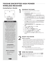
25. Wiring Details and Diagrams
The following section includes kit wiring diagrams.

4 Digital Monitoring Products Generic Bank Branch Large Quick Start Guide (KIT-XXX-XL550BRANCH)
Conduit
Conduit
J14
J12J10
J7
J5
TXD
J2
KYPD LX
Z13+
Z13-
Z14+
Z14-
Z15+
Z15-
Z16+
Z16-
Z9+
Z9-
Z10+
Z10-
Z11+
Z11-
Z12+
Z12-
Z5+
Z5-
Z6+
Z6-
Z7+
Z7-
Z8+
Z8-
Z1+
Z1-
Z2+
Z2-
Z3+
Z3-
Z4+
Z4-
BLK
GRN
YEL
RED
J3
1k EOL
TENS ONES
J14
J12J10
J7
J5
TXD
J2
KYPD LX
Z13+
Z13-
Z14+
Z14-
Z15+
Z15-
Z16+
Z16-
Z9+
Z9-
Z10+
Z10-
Z11+
Z11-
Z12+
Z12-
Z5+
Z5-
Z6+
Z6-
Z7+
Z7-
Z8+
Z8-
Z1+
Z1-
Z2+
Z2-
Z3+
Z3-
Z4+
Z4-
BLK
GRN
YEL
RED
J3
1k EOL
TENS ONES
J14
J12J10
J7
J5
TXD
J2
KYPD LX
Z13+
Z13-
Z14+
Z14-
Z15+
Z15-
Z16+
Z16-
Z9+
Z9-
Z10+
Z10-
Z11+
Z11-
Z12+
Z12-
Z5+
Z5-
Z6+
Z6-
Z7+
Z7-
Z8+
Z8-
Z1+
Z1-
Z2+
Z2-
Z3+
Z3-
Z4+
Z4-
BLK
GRN
YEL
RED
J3
1k EOL
TENS ONES
AC and battery
supervision relay
connections.
1K Ohm resistor in Series
with Common
14 AWG Ground Wire
318EXT Harness
357-10 Cat 5e Network Cable
From 714-16 J5 Header to
XR550 J14 LX500 Connector
Power Supply AC Trouble (Z6)
Power Supply Battery Trouble (Z5)
307-S
Screw-on
Tamper
Switch
307-S
Screw-on
Tamper
Switch
Violet
Gray
Connect through conduit to
optional fourth 714-16 mounted in separate enclosure
with eight batteries.
To Auxiliary devices / 861
Common from DC- to Panel Terminal 10
Earth Ground
3/4" Conduit 3/4" Conduit
318EXT Harness
PTC
Tamper Wire
From TAMPER Header
to top battery tamper
From bottom battery tamper
to top panel tamper
From bottom panel tamper
to top panel tamper
From TAMPER Header
to bottom panel tamper
318EXT Harness
to 318 Harness
PTC
318
Battery Harness
Red
Black
PTC
318R Battery Harness
318 Battery Harness
Red
Black
PTC PTC
PTC
318R Battery Harness 318R Battery Harness
Cut and insulate
the non-PTC ends
of the 318R
battery harness
Red
Black
PTC
318R Battery Harness
12 VDC 18 Ah Battery 1 12 VDC 18 Ah Battery 2
12 VDC 18 Ah Battery 3 12 VDC 18 Ah Battery 4
12 VDC 18 Ah Battery 5 12 VDC 18 Ah Battery 6
1-1/2" Conduit 7070 Keypad
Address 1
7070 Keypad
Address 2
From 861
307-S
Screw-on
Tamper
Switch
307-S-REED
Screw-on
Tamper
Switch
Can be extended
up to 500 feet
from the panel
using 22 AWG
or 1000 feet
using 18 AWG
75VA
50VA
75VA Jumper
Setting
381-12
SMA Cable
386 Antenna
Mount
383 Antenna
AC
1 2 3 45 6 7 8 10 11 12 13 14 15 16 17 18 199 20 21 22 23 25 26 27 28
+B BELLGND SMK GNDRED YEL GRN BLK Z1 Z2 Z3 Z4 Z5 Z6 Z7
24
Z8 Z9+ Z9– Z10+ Z10–AC –B GND GND GNDGND
K
J16
263LTE-V
XR550DE Panel
714-16
714-16
714-16
431 Output
Harness
305
Output
Relay
305
Output
Relay
Network
(LAN/WAN)
Connection
DC
AC
Trouble
Batt
Trouble
Green
LED
AC
Red
LED
DC
Battery
Start
BAT
Model 505-12
J2
KYPD LX
TENS ONES
J2
KYPD LX
TENS ONES
1 6
J2
KYPD LX
TENS ONES
3 2
Transformer
16 VAC 100 VA
16 VAC 100 VA
Green/
Yellow
Stripe
Black
White
Black
Black
White
Green
White
Plug into dedicated
120 VAC 60 Hz outlet
not controlled by a
switch.
Mount the 861 directly
to the side of the 352
enclosure, to the left
of the XR550DE panel.
LEV
RED POWER OUT BLACK GROUND OUT
J12
J1
J2
J14
J11
J9
J7
J5
J17
J15
J13
J10
J8
J6
J4
J3
J16
J18
RB BR
Black
Red
MODEL
861
4-Wire
Bus-A
4-Wire
Bus-B
RED
PWR IN
BLK
GND IN
To 7060 Thinline LCD Keypad
To External 2-Wire Devices
(Motion detector, glassbreak, PIR, etc.)
To 505-12:
DC+ (Red)
DC- (Black)
To Panel Prog Header
To Panel
Terminal 10
572 Panic LEDs
1k EOL
No Connection
381-12
SMA Cable
383 Antenna
386 Antenna
Mount
SMA
Connector
263LTE-V
Nut
Washers
SMA
Connector
Coax Cable
from 263LTE-V
Model 381-2
Coax Cable from
the 263LTE-V module
PCB
Stando
C1 C4
U1
U2
CR3 TXD
J1
R
E
D
Tens Ones
714
Module
From LX-Bus
of the last
714-16 module
White/Yellow - Zone 4
White/Orange - Zone 3
White/Red - Zone 2
White/Brown - Zone 1
Black
Green
Yellow
Red
+
–
714 Normal operating range:
650 - 2100 Ohms
18 AWG non-shielded non-twisted cable
between zone expander and control panel
From 861 12 VDC terminals
+
-
To Seismics, Motions and
other powered devices other
than the zone expander or keypad
ATM Pre-installed 714 module
+
-
1K EOL
+
–
1K EOL
+
–
1K EOL
+
–
1K EOL
861 Wiring
1100XH
263LTE-V Installation Detail
DMP 352P (Panel Enclosure) DMP 352S (Battery Enclosure)
Red
Black
RF RX
RF TX
PANEL RX
PANEL TX
WALL
TAMPER
ENABLE
DISABLE
STAT US
PWR
2"
2"
Figure 1: Wiring Diagram
/