Page is loading ...

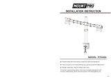
Dual Monitor Desk Mount
Instruction Manual
If you have any questions, please feel free to contact our customer service via Amazon.
75x75
100x100
13~32"
each arm
9kg
19.8 lbs
MS-02N-US3.0

If this mount is NOT compatible, please contact our customer service to nd a compatible mount.
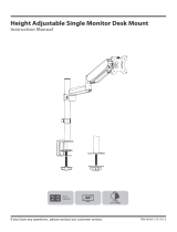
Must Check Before Installation
MAX:100mm
MAX:
100mm
1. Is your monitor VESA 75×75mm/3x3" or 100×100mm/4x4"?
Yes — Perfect!
No — This mount is NOT compatible.
19.8 lbs / 9kg
each arm
2. Is the weight of your monitor (including accessories) less than 19.8 lbs (9kg)
each arm?
Yes — Perfect!
No — This mount is NOT compatible.
10~50mm
Desk
3. Is your desk thickness 10~50mm (0.39~1.97”)?
Yes — Perfect!
No — This mount is NOT compatible.
01

NOTE: Not all hardware included will be used.
Improper installation may cause damage or serious injury. Do not use this product for any purpose
that is not explicitly specied in this manual. We cannot be liable for damage or injury caused by
improper mounting, incorrect assembly or inappropriate use.
This product contains small items that could be a choking hazard if swallowed. NOT FOR CHILDREN
UNDER 3 YEARS. ADULT SUPERVISION IS REQUIRED.
WARNING!
02
Supplied Parts List
G (x1)
5mm Allen Key
F1 (x1)
Wire Clip
F2 (x4)
Wire Clip
G (x1)
6mm Allen Key
A (x2)
Nut M6
B (x2)
Bolt M6mm
C (x8)
Bolt M4×30mm
D (x8)
Bolt M4×12mm
E (x8)
Spacer L10mm
a (x1)
Pole
b (x1)
Swivel Arm
c (x2)
VESA Plate
G (x1)
3mm Allen Key
d1
Bracket
d (x1)
Clamp
d2
Bolt Y
d3
Bolt
d4
Clip Plate
All are included in d
e (x1)
Pad

03
ASSEMBLY STEPS
Warm Tips You could also refer to the Video Guide about installation on our product page.
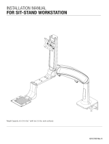
STEP 2: Clamp Installation OR Grommet Base Installation
OPTION A: Clamp Installation
1. Mount Clamp (d) to the bottom of Pole (a) by tightening bolts (B) with 5mm Allen Key (G).
2. Adjust the Clamp width to t your desk. Secure stand to the desktop by tightening Clamp (d).
d
G
a
B
10 - 50mm
0.39 - 1.97”
Apply pad (e) to the Pole (a) bottom to avoid desk scratches.
STEP 1: Apply Pad to the Pole Bottom
a
e

04
STEP 2: (Continued)
OPTION B: Grommet Base Installation
1. If existing grommet hole comes with a plastic protector, remove it to ensure a at surface before installing
the desk mount.
2. Detach Bracket (d1) and Bolt Y (d2) from Clamp (d).
3. Position pole (a) on the mounting surface and then secure it by tightening the plastic knob after making
Bolt Y (d2) through the Bracket (d1), desk hole, and the bottom of Pole (a) sequentially.
a
d1
d2
DESK
DESK
ø 10~60mm
ø 0.39~2.36"
d
d1 d2
10 - 50mm
0.39 - 1.97”

STEP 2: Install Arm to the Pole
1. Install Wire Clip (F1) and Swivel Arm (b) to the Pole (a).
a
F2
F1
b
2. Fasten the bolt with supplied Allen Key (G 6mm).
3. Attach the Wire Clip (F2) to the Swivel Arm (b).
b
Please do not move stand outside desk for safety!
DESK
05
G 6mm

OPTION A: Flat Back Monitor
Attach the VESA plate (c) to the monitor with M4×12 bolts (D).
NOTE: Hand tighten screws to avoid over tightening.
STEP 3: Attach the VESA Plate to the Monitor
OPTION B: Curved or Recessed Back Monitor
Attach the VESA plate (c) to the monitor with M4×30 bolts (C) and M4 spacers (E).
NOTE: Hand tighten screws to avoid over tightening.
c
D
c
E
C
06

STEP 4: Slide the Monitor onto the Head of Swivel Arm
Slide the monitor onto the head of Swivel Arm (b) as shown in diagram.
Install the security Nut (A). Make sure the security nut is installed before you rotate the
monitor.
b
07
A

STEP 5: (Continued)
STEP 5: Make the Necessary Adjustments
Tighten the bolt with the supplied Allen Key (G 5mm) to x the tilt angle.
Use the supplied Allen Key (G 5mm) to make the necessary adjustments.
Ignore this step if the arm joint has screwed to the proper tightness
Fix the tilt angle
G 5mm
±90°
±90°
±90°
Fix the tilt angle
Fix the swivel angle
Note: When tilted, if the monitor sags or does not stay,
and if the above method is useless, please feel free to
contact our customer service.
08
-90°
+90°
G 5mm

STEP 6: Adjust the Level of Monitor and Manage the Wires
Manage the wires and store the Allen keys (G 6mm, G 5mm, G 3mm) in Wire Clip (F1) for
future use.
Ignore this step if monitors are level
For minor height adjustment, remove the Nut (A) and turn the bolt with the supplied
Allen key (G 3mm) to raise or lower the monitor. Install the Nut(A) after the adjustment.
09
A
G 3mm
G 6mm
G 5mm
G 3mm
F1

Product Dimensions
10
100mm/3.94”
75mm/2.95”
100mm/3.94”
75mm/2.95”
113mm/4.45”
113mm/4.45”
159mm
/6.26”
184mm
/7.24”
37mm
/1.46”
71mm
/2.8”
10 ~ 50mm
0.39 ~ 1.97”
420mm/16.54”
720mm
/28.35”

• Never allow children to climb, stand, hang, or play on any part of monitor or stand.
• This product is intended for indoor use only. Using this product outdoors could lead to
product failure and personal injury.
• Check that the bracket is secure and safe to use at regular intervals
(at least every three months).
CAUTION AND MAINTENANCE:
/