Page is loading ...

Features
Releasing control using the Simplex
®
4100ES
(or 4100U) Fire Alarm Control Panel to provide**:
Coverage for multiple areas of Automatic Extinguishing
Release and/or Deluge and Preaction Sprinkler System
Release including audible escalation of events
Control of compatible Listed/Approved 24 VDC
automatic control actuators, one per circuit; or two
12 VDC actuators in series per circuit
Releasing appliance circuits (RACs) by connecting
Notification appliance circuits (NACs) to Suppression
Release Peripherals for actuator supervision and control
Audible Escalation of Events:
Temporal or 20 bpm March Time pattern for first
cross-zone alarm
120 bpm March Time pattern to indicate releasing timer
active
On steady to indicate releasing timer expired and
actuator is activated
NOTE: Requires NACs dedicated to conventional horn
control (not SmartSync™ operation) with strobes
controlled on separate NACs
4090-9005/-9006 Suppression Release Peripheral
(SRP) with Dual Command Control:
Dual command control requires that both IDNet™
communications commands and an activated NAC are
present to initiate the desired release
NAC provides wiring supervision to the actuator
including monitoring of coil continuity and short circuit
supervision to the coil supervision module
Suppression Release Peripheral control features:
An on-board DC-DC regulator compensates for
voltage drops to the peripheral and ensures proper
control circuit voltage over a wide operating range
Provides a single RAC for control of actuators for up
to 2 A using a 3 A NAC input (1 A using a 2 A NAC
input)
Related system components:
4100ES Series control panel with Releasing Appliqué
Dedicated NAC output from 4100ES (or compatible
NAC Extender)
Coil supervision module, one per RAC
Maintenance Switch, one per RAC
Abort Switch connected via an addressable interface
module
UL listed to Standard 864
* This product has been approved by the California State Fire Marshal (CSFM) pursuant to
Section 13144.1 of the California Health and Safety Code. See CSFM Listings
7165-0026:251 and 7300-0026:313 (SRP) for allowable values and/or conditions
concerning material presented in this document. It is subject to re-examination, revision,
and possible cancellation. Additional listings may be applicable; contact your local Simplex
product supplier for the latest status. Listings and approvals under Simplex Time Recorder
Co. are the property of Tyco Safety Products Westminster.
Agent
source
Agent
discharge
path
Actuator
Control
Circuit
Actuator
Maintenance
Disconnect Switch
(with indicator lamp)
Coil supervisory
module
COIL SUP E RV ISION MODUL E ( 2 AMP ) 20 8 1 - 90 4 6
INSTA L L A T ION INSTR UC T IONS 57 4 - 4 3 7 RE V
MAINTA IN 1/4" SE PA R AT ION
BET W E EN POW E R LIMITED
( RE D /BL K) AND NON PO W ER
LIMITED (Y E L /BL K ) W IRING
RED
NAC+
NAC-
BL K
DAT E CODE : 51 9 - 95 8
YEL
BL K
S
SIM P L E X T IME R E C O R D E R C O . GA R D N E R M A . US A
FIRE
RELEASING
DEVICE
Dedicated
NAC circuit
IDNet
communications
Typical addressable
initiating devices
MANUAL
RELEASE
Release
appliance circuit
4100ES Control Panel with
Suppression Release Appliqué
Suppression
Release Peripheral
- IDNET IN +
+IDNET IN -
PUSH AND HO LD
FIRE SUPPRESSION
SYSTEM ABOR T
NORMAL
DISC.
/
DISABLE
FIRE SU PPRESSION
DISCONN ECT / DISABL E
0
1
Power for
indicator lamp
(if required)
SUPPRESSION RELEA SE PANEL
CAUTION: This Control Unit has been arranged for releasing
service. Disable all releasing device circuits prior to servicing.
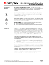
4100ES Series Releasing Control Typical Block Diagram
Introduction
When combined with Suppression Release Peripherals,
the 4100ES series fire alarm control panel provides
actuator supervision and control for use in automatic
extinguishing, and deluge or preaction releasing systems.
Hazard area initiating and notification devices are
controlled using either conventional or addressable
circuits per standard 4100ES capabilities. The necessary
releasing system logic is implemented within the 4100ES
control panel as required for the local application.
** Release Control operation described in this document is also available with 4100U
Control Panels with software revision 11.05 or higher. Refer to data sheet S4100-0031
for model 4100ES control panel details including IDNet communications information.
Fire Control Panels
UL, ULC, CSFM Listed; FM Approved Automatic Extinguishing, Deluge and Preaction
MEA (NYC) Acceptance* Sprinkler System Releasing Control
S4100-0040-5

Automatic Extinguishing Release Systems
These systems automatically activate electrically
controlled actuators for the release of a fire extinguishing
agent (such as dry chemical, water spray, foam, CO
2
,
or
clean agent) in response to fire detection device inputs as
determined by programming of the host fire alarm control
panel.
Automatic Extinguishing Release System Panels
are required to have a minimum of 24 hours of standby
power. Initiating devices must be Listed/Approved for the
application, and may be wired either Class A or B.
Control actuators must be electrically compatible with the
control panel circuits and power supplies, and are wired
Class B to provide coil supervision.
Deluge or Preaction Sprinkler Systems
These systems automatically activate water control
actuators in response to fire detection device inputs.
Deluge Sprinkler Systems employ open sprinkler
heads and provide water flow when the fire detection
system activates a common automatic water control
actuator. They are used to deliver water simultaneously
through all of the system sprinkler heads. This type of
system is applicable where the immediate application of
large quantities of water over large areas is the proper fire
response.
Preaction Sprinkler Systems are similar to deluge
systems except that normally closed sprinkler heads are
used and supervisory air pressure is maintained in the
pipe. Operation requires both an activated sprinkler head
and an activated fire alarm initiating device with specific
programming determined at the host fire alarm control
panel.
Releasing System Requirements
1. Releasing actuators are controlled from a
Suppression Release Peripheral (4090-9005 or
4090-9006). Connections are 2-wire, Class B releasing
circuits with only one 24 VDC actuator per circuit.
Where applicable, two, 12 VDC actuators in series, or
one 12 VDC actuator with manufacturer supplied
resistor may be used.
2. Coil Supervision Module 2081-9046 must be wired
electrically before the actuator and located in the
actuator wiring junction box. (Refer to diagram on
page 5.) The connected RAC provides continuity
supervision of the actuator coil and wiring and
provides short circuit supervision to the coil
supervision module.
3. Cross-zoning or other alarm initiation logic per
system requirements, is to be implemented by
programming at the fire alarm control panel.
4. UL Listed Automatic Extinguishing Releasing
operation requires that: battery standby must be a
minimum of 24 hours with 5 minutes of alarm and that
listed actuators are used, refer to list on page 6.
Releasing System Requirements (Continued)
5. FM Approved Automatic Extinguishing Release
requires secondary standby to be a minimum of
24 hours with 5 minutes of alarm. Actuators must be
electrically compatible.
6. FM Approved Deluge and Preaction Sprinkler
operation requires that: initiating device circuits be
Class A and wired to Listed/Approved devices;
standby power capacity must be a minimum of 90
hours with 10 minutes of alarm; and that compatible
Automatic Water Control Valves must be used. (Refer
to actuator list on page 7.)
7. Maintenance Switches, one per RAC, are required
per NFPA 72
®
, the National Fire Alarm Code
®
(2002
Edition, Chapter 6) to allow the system to be tested or
serviced without actuating the fire suppression
systems. Their use may not be allowed in some
jurisdictions, always confirm local requirements.
When used, Simplex Maintenance Switches are
required to ensure that operation initiates a
supervisory condition.
8. Abort Switches are available when abort operation is
required. When used, connect to an addressable
Supervised IAM model 4090-9001 or similar
addressable adapter module. The Simplex abort switch
and the IAM mount in a single gang box, 2-1/2”
minimum depth.
9. Addressable Manual Releasing Stations are used to
initiate activation of the releasing actuators with the
appropriate time delay implemented by the fire alarm
control panel.
10. Notification Requirements. Each hazard area
typically requires general audible and visible fire
alarm notification and additional dedicated NACs for
area releasing status notification. Suppression
releasing is compatible with conventional panel
mounted NAC modules as well as for use with the
4009 IDNet NAC Extender.
11. Additional Suppression Release Peripheral
Reference. Refer to Installation Instructions 579-385.
Additional Releasing Systems Reference
For additional information, refer to Factory Mutual
Research Corporation (FMRC) “FMRC Approval Guide,”
FM Approval standard “Deluge Systems and Preaction
Systems.”
Please note that proper operation of releasing control
systems requires that the system design, installation, and
maintenance be performed correctly and in accordance
with all applicable local and national codes, and
equipment manufacturer’s instructions. No liability for
total system operation is assumed or implied.
2 S4100-0040-5

3 S4100-0040-5
4100ES Releasing Control System Modules
Model
Description
Reference
2081-9046
Coil Supervision Module
Required, one per RAC, mounts in the releasing actuator wiring
junction box; see specifications section for details
2080-Series*
Maintenance Switches
One per RAC; flush or surface mount; indicator lamp models
require separate 24 VDC wiring
2080-9056*
Flush mount
Abort Switch
As required, connects via an IDNet addressable interface module;
mounted on a single gang stainless steel plate; installation
requires a single gang box, 2-1/2” (64 mm) minimum depth
2080-9057*
Surface mount
* Refer to data sheet S2080-0010 for Abort and Maintenance switch details.
Releasing Appliqués, Required for 4100ES Suppression Releasing Applications
Model
Description
4010-9830
English
Suppression Releasing Appliqué; field applied (same appliqué as is used on the
Simplex model 4010 Suppression Release Panel)
4010-9830CAF
French
Suppression Release Peripheral and Accessories
Model
Description
Reference
4090-9005
Basic Suppression Release Peripheral on
mounting plate
Requires mounting box 2975-9227, ordered separately
4090-9006
Suppression Release Peripheral mounted in
red box; required for ULC listing
Includes LED indicator on front of door
2975-9227
Red mounting box; required for 4090-9005
These items are included with model 4090-9006
4090-9812
Red LED IDNet communications indicator
option kit; mounts on door of 2975-9227 box
Subject
Data Sheet
Subject
Data Sheet
Releasing System Abort and Maintenance
Switches
S2080-0010
4100 Series, Panel Mount 24 Point I/O and
Annunciator Modules
S4100-0032
Addressable Manual Stations for Releasing
Applications
S4099-0002
4100 Series, Remote Mount 24 Point I/O and
Annunciator Modules
S4100-0005
Addressable Manual Stations for Standard
Applications
S4099-0001
TrueAlarm
®
Sensors and Bases
S4098-0019
4100ES Basic Control Panels
S4100-0031
TrueAlert
®
Electronic Horns
S4901-0010
Supervised IAM
S4090-0001
TrueAlert Non-Addressable Strobes (V/O)
S4906-0001
Addressable Zone Adapter Modules
S4090-0003
TrueAlert Non-Addressable 4-Wire Horn/Strobes (A/V)
S4903-0011
Contact your local Simplex product supplier for additional information on compatible IDNet addressable devices and TrueAlert
notification appliances.
Product Selection
Additional Product Data Sheet Reference

4 S4100-0040-5
Class B NAC wiring; dedicated to
Suppression Release Actuator
IDNet communications
(shown as Class B wiring)
IDNet Addressable devices
Suppression Release Appliqué wording:
4090-9005/-9006 Suppression
Release Peripheral
Supervised IAM with
optional Abort Switch
FIRE
RELEASING
DEVICE
MANUAL
RELEASE
- IDNET IN +
+IDNET IN -
MANUAL
RELEASE
- IDNET IN +
+IDNET IN -
PUSH A ND HO LD
FIRE SUPPRESSION
SYSTEM ABORT
PUSH A ND HO LD
FIRE SUPPRESSION
SYSTEM ABORT
NORMAL
DISC.
/
DISABLE
FIRE S UPPR ESSION
DISCON NECT / DISAB LE
0
1
Agent
source
Agent discharge path
Actuator Control Circuit
Actuator
Coil supervisory
module
COIL SUPE R VISION MODULE ( 2 AMP) 20 8 1 - 90 4 6
INSTA L LA T ION INSTRUC TIONS 57 4 - 4 3 7 REV
MAINTA IN 1/4" SEP AR AT ION
BE TW EE N POW ER LIMITED
(R ED /BL K ) AND NONPO W E R
LIMITED ( YE L /BL K) W IRING
RED
NAC+
NAC-
BL K
DAT E COD E: 51 9 - 9 5 8
YEL
BL K
S
S IMP L E X T IME RE C O R D E R C O . G A R D N E R MA . US A
24 VDC for Maintenance Disconnect
status indicator (if required)
4100ES Control Panel with
Suppression Release Appliqué
HAZARD AREA 1
HAZARD AREA 2
Maintenance
Disconnect
Switch
FIRE
RELEASING
DEVICE
NORMAL
DISC.
/
DISABLE
FIRE S UPPR ESSION
DISCON NECT / DISAB LE
0
1
Agent
source
Agent discharge path
Actuator Control Circuit
Actuator
Coil supervisory
module
COIL SUPE R VISION MODULE ( 2 AMP) 20 8 1 - 90 4 6
INSTA L LA T ION INSTRUC TIONS 57 4 - 4 3 7 REV
MAINTA IN 1/4" SEP AR AT ION
BE TW EE N POW ER LIMITED
(R ED /BL K ) AND NONPO W E R
LIMITED ( YE L /BL K) W IRING
RED
NAC+
NAC-
BL K
DAT E COD E: 51 9 - 9 5 8
YEL
BL K
S
S IMP L E X T IME RE C O R D E R C O . G A R D N E R MA . US A
IDNet communications
Class B NAC wiring; dedicated to
Suppression Release Actuator
NAC for strobe control
NAC for horn control
Use separate NACs
for horn and strobe
control to implement
audible escalation of
events
Use separate NACs
for horn and strobe
control to implement
audible escalation of
events
NAC for strobe control
NAC for horn control
SUPP RESS ION RE LEASE PANE L
CAUTIO N : This Control Unit has been arr anged f or r eleasing
service . Disable all r eleasing device circuits prior to ser vicing .
SUPPRESSION RELEASE PANEL
CAUTION: This Control Unit has been arranged for releasing
service. Disable all releasing device circuits prior to servicing.
4100ES Releasing System One-Line Connection Reference

Maintenance Disconnect Switch
FIRE
RELEASING
DEVICE
Class B NAC wiring
dedicated to Suppression
Release Peripheral
IDNet communications,
Class A or Class B
Addressable devices
Release appliance
circuit
Valve wiring
junction box
Coil Supervision
Module 2081-9046
CO IL S UP E RV IS ION MOD UL E ( 2 A MP ) 20 8 1 - 9 0 4 6
IN ST A L L A T ION IN ST R UC TION S 5 7 4 - 4 3 7 R E V
MA INT A IN 1 /4 " SE PA R AT IO N
B ET W E EN P OW E R L IMIT ED
( R ED /B L K) A ND N ONP OW E R
L IMIT E D ( Y E L /B L K ) W IR ING
RE D
N AC +
N AC -
B L K
DA T E CO DE : 5 1 9 - 9 5 8
Y EL
B L K
S
S IM P L E X T IM E R E C O R D E R C O . G A R D N E R M A . U S A
Listed/approved actuator or
Deluge and Preaction
Automatic Water Control
Valve; one if 24 VDC (or 2 in
series if 12 VDC) per RAC
Blk
Yel
S
Blk
Red
-
-
Out
In
+
+
MANUAL
RELEASE
4090-9005/-9006 Suppression
Release Peripheral
- IDNET IN +
+IDNET IN -
Supervised IAM with
optional Abort Switch
To 4100ES, 4100U or 4009 IDNet NAC Extender
2080-9056/-9057 Abort
Switch (as required)
Maximum Notification Appliance Circuit (NAC) Wiring Distances to a Suppression Release Peripheral
(0.5 A to 1.75 A drop is based on a total drop of 3.4V; 2 A drop is based upon a total drop of 1.2 V)
Distance
RAC Output Current
(refer to solenoid
rating)
18 AWG
16 AWG
14 AWG
Total Line
Resistance
0.50 A
250 ft
76 m
399 ft
122 m
635 ft
194 m
3.58
0.75 A
167 ft
51 m
266 ft
81 m
423 ft
129 m
2.39
1.00 A
125 ft
38 m
199 ft
61 m
317 ft
97 m
1.79
1.25 A
100 ft
30 m
159 ft
48 m
254 ft
77 m
1.43
1.5 A
84 ft
26 m
133 ft
41 m
212 ft
65 m
1.19
1.75 A
72 ft
22 m
114 ft
35 m
181 ft
55 m
1.02
2.00 A
25 ft
7.6 m
39 ft
12 m
63 ft
19 m
0.36
Metric wire equivalents: 18 AWG = 0.82 mm
2
; 16 AWG = 1.31 mm
2
; 14 AWG = 2.08 mm
2
Maximum Release Appliance Circuit (RAC) Wiring Distances from Suppression Release Peripheral to
the Valve Solenoid (based on a total drop of 0.6 V)
Distance
RAC Output Current
(refer to solenoid
rating)
18 AWG
16 AWG
14 AWG
Total Line
Resistance
0.50 A
74 ft
23 m
118 ft
36 m
188 ft
57 m
1.06
0.75 A
50 ft
15 m
79 ft
24 m
126 ft
38 m
0.71
1.00 A
37 ft
11 m
59 ft
18 m
94 ft
29 m
0.53
1.25 A
30 ft
9 m
47 ft
14 m
75 ft
23 m
1.06
1.5 A
25 ft
7.6 m
39 ft
12 m
63 ft
19 m
0.71
1.75 A
21 ft
6.4 m
34 ft
10 m
54 ft
16 m
0.53
2.00 A
19 ft
5.8 m
30 ft
9 m
47 ft
14 m
0.53
Metric wire equivalents: 18 AWG = 0.82 mm
2
; 16 AWG = 1.31 mm
2
; 14 AWG = 2.08 mm
2
PUSH AND HOLD
FIRE SUPPRESSION
SYSTEM ABORT
NORMAL
DISC.
/
DISABLE
FIRE SUPPRESSION
DISCONNECT / DISABLE
0
1
PUSH AND HOLD
FIRE SUPPRESSION
SYSTEM ABORT
NORMAL
DISC.
/
DISABLE
FIRE SUPPRESSION
DISCONNECT / DISABLE
0
1
24 VDC power
for indicator lamp
(2 wires)
5 S4100-0040-5
Suppression Release Peripheral Wiring Reference

6 S4100-0040-5
Suppression Release Peripheral 4090-9005 and 4090-9006
Communications
IDNet, one address
RAC Output
Rating
with 4100ES/4100U
2 A maximum
At nominal 24 VDC, regulated; refer to NAC Power
Requirements for more detail
with 4009 IDNet NAC Extender
1 A maximum
NAC Power Requirements
NOTE: 4100ES NACs are
rated at 3 A; 4009 IDNet
NAC Extender NACs are
rated at 2 A, Extender
expansion NACs are rated
1.5 A
Voltage
16 to 32 VDC (nominal 24 VDC)
Supervisory Current
No additional current required, circuit appears as standard end-of-line (EOL)
NAC loading
Alarm Current
Reference
(RAC current =
actuator current)
RAC Current
NAC Current
RAC Current
NAC Current
0.5 A
0.845 A
1.25 A
2.14 A
0.75 A
1.28 A
1.5 A
2.56 A
0.87 A
1.5 A
1.75
3 A
1 A
1.71 A
2 A
Wire Connections
Screw terminals for input and output wiring, 18 to 12 AWG wire
(0.82 mm
2
to 3.31 mm
2
)
IDNet Wiring Distance Reference
Up to 2500 ft (762 m) from the IDNet source module
Up to 10,000 ft (3048 m) total Class B wiring distance including T-Taps
Compatible with Simplex 2081-9044 Overvoltage Protectors
Dimensions
See installation reference on page 8
Operating Temperature
32° to 120° F (0° to 49° C) indoor operation only
Operating Humidity Range
10 to 90% RH at 90° F (32° C)
Coil Supervision Module 2081-9046
Construction
Epoxy encapsulated
Dimensions
1-3/8” W x 2-7/16” L x 1-1/16” H (34 mm x 62 mm x 27 mm)
Wiring
18 AWG (0.82 mm
2
) wire leads, color coded
Current Rating
2 A Maximum; internally fused at 3 A, non-replaceable
MFG.
Model Number
Coil Details
MFG.
Model Number
ANSUL
*AUTOMAN II-C Assembly; solenoid
17728; coil 25924
12 VDC, 458 mA
ASCO
8210A107 (097617-005D coil) 1/2” NPS, 5/8” orifice,
24 VDC
AUTOMAN II-C Explosion-Proof
Releasing Device; solenoid 31492; coil
31438
24 VDC, 467 mA
8210G207 (238310 coil) 1/2” NPS, 1/2” orifice
*AUTOMAN II-C Assembly; solenoid
68739; coil 25924,
12 VDC, 458 mA
8211A107 (097617-005D coil) 24VDC
Solenoid Electric Actuator; solenoid
73111; coil 73097
24 VDC, 1 A
HV2628571 (23810 coil) N.C. 1/2” NPS, 1/2” orifice
*CV90 HF Electric Actuator 73327; may
use 73606 in-line resistor for 12 VDC
9 VDC max,
450 mA
HV2648581 (23810 coil) N.O. 1/2” NPS, 1/2” orifice
R8210A107 (097617-005D coil) 1/2” NPS, 5/8” orifice
LP CO2 w/ASCO solenoid 422934,
24 VDC, 442 mA
T8210A107 (097617-005D coil) 1/2” NPS, 5/8” orifice
LP CO2 double action solenoid 430948
24 VDC, 438 mA
Pyro-
Chem
ECH Electrical Control Head (551201)
LP CO2 3-way selector valve solenoid
433419
24 VDC, 438 mA
Explosion-Proof Electric Actuator (570147)
Electric Actuator 24 VDC solenoid
570537
24 VDC, 250 mA
Removable Electric Actuator (570209) 0.2 A
Skinner
71395SN2ENJ1NOH111C2 (Skinner coil H111C2) 1/4”, NPS, 1/16”
73212BN4TN00NOC111C2 (Skinner coil C111C2) 1/2”, 5-300 psi
73212BN4TNLVNOC322C2 (Skinner coil C322C2) 1/2”, NPS, 0.92 A, 250 psi
73218BN4UNLVNOH111C2 (Skinner coil H111C2)
73218BN4UNLVNOC111C2 (Skinner coil C111C2) 1/2”, NPS, 5/8 in. orifice
* 12 VDC coils, either wire two in series for 24 VDC activation, or, if available from manufacturer, use series resistor
Specifications
Compatible UL Listed Valves and Actuators

7 S4100-0040-5
FM
Group
Manufacturer
Model Number
Details
A
Skinner
LV2LBX25*
24 VDC, 11 W, 458 mA, 1/2 inch NPS, 1/2 inch orifice
B
ASCO
T8210A107
24 VDC, 16.8 W, 700 mA, 1/2 inch NPS, 5/8 inch orifice
R8210A107
8210A107
D
ASCO
8210G207
24 VDC, 10.6 W, 440 mA, 1/2 inch NPS, 1/2 inch orifice
E
Skinner
73218BN4UNLVNOC111C2*
24 VDC, 10 W, 420 mA, 1/2 inch NPS, 5/8 inch orifice
73212BN4TN00N0C111C2
24 VDC, 10 W, 420 mA, 1/2 inch NPS, 5/8 inch orifice; 5-300 psi rated
working pressure
F
Skinner
73212BN4TNLVNOC322C2
24 VDC, 22 W, 1/2 inch NPS, 920 mA, 250 psi (1725 kPa), 1/2 inch orifice
G
Skinner
71395SN2ENJ1NOH111C2
24 VDC, 10 W, 420 mA, 1/4 inch NPS, 1/16 inch orifice, 250 psi
(1725 kPa) rated working pressure
I
Vitaulic
Series 753-E solenoid valve
24 VDC, 8.7 W, 1⁄2 inch NPS, 364 mA, 300 psi (2069 kPa), 1⁄2 inch orifice
J
Viking
11591 and 11592
Normally closed (NC)
Explosion proof solenoid valves, 24 VDC, 10 W,
1⁄2 inch NPS, 300 psi (2069 kPa), 4.1 Cv
11595 and 11596
Normally open (NO)
K
Viking
11601 and 11602
NC solenoid valve, 24 VDC, 9 W, 1⁄2 inch NPS, 250 psi (1725 kPa), 6.2 Cv
* For new applications, LV2LBX25 has been replaced by model number 73218BN4UNLVNOC111C2.
FM Approved Water Control Valves

Tyco Safety Products Westminster • Westminster, MA • 01441-0001 • USA S4100-0040-5
www.tycosafetyproducts-usa-wm.com
© 2011 Tyco Safety Products Westminster. All rights reserved. All specifications and other information shown were current as of document revision date and are subject to change without notice.
Door width
6-1/8" (156 mm)
Box depth
4" (102 mm)
Box depth with door
4-1/16" (103 mm)
Door height
8-1/8"
(206 mm)
4 Knockouts,
one each side
Door hinges on left and
lifts off for access
4090-9812 LED indicator
option (supplied with
4090-9006)
Door screw
fastener
Door depth
1/2" (13 mm)
2975-9227 Box, red with white
lettering (supplied with 4090-9006)
Box width
6" (152 mm)
Box height
8" (203 mm)
4090-9005 Suppression
Release Peripheral assembly
(supplied with 4090-9006)
NAC -NAC +
IDNet-IDNet+
RAC -RAC +
IDNET SUPPRESSION RELEASE PERIPHERAL ASSY 566-104
ON
1 2 3 4 5 6 7 8
Tyco is a registered trademark of Tyco International Services GmbH and is used under license. Simplex, the Simplex logo, TrueAlarm, TrueAlert, SmartSync, and IDNet are
trademarks of Tyco International Ltd. and its affiliates and are used under license.
Suppression Release Peripheral Installation Reference Diagram
/