
Preaction System with DV-5 Deluge Valve
Double Interlock — Electric/Electric Actuation
Page 1 of 14 DECEMBER 2014 TFP1465
Worldwide
Contacts
www.tyco-fire.com
General
Description
The TYCO DV-5 Double Interlock Pre-
action System with Electric/Electric
Actuation (Fig. 1) is designed for use
in applications, such as refrigerated
areas, requiring the maximum degree
of protection against inadvertent flood-
ing of the sprinkler system piping.
The DV-5 Double Interlock Preaction
System with Electric/Electric Actua-
tion utilizes a DV-5 Deluge Valve and
a Riser Check Valve. The Riser Check
Valve (that does not require the use
of priming water) isolates the Deluge
Valve from the system air pressure. The
releasing trim for the Deluge Valve uti-
lizes a Solenoid Valve that is operated
by energizing the releasing circuit of a
Cross-Zone Deluge Valve Releasing
Panel (automatic control unit).
Zone 1 of the Releasing Panel is oper-
ated by either a fire detection device
or manual pull station. Zone 2 of the
Releasing Panel is operated by a Low
Air Pressure Alarm Switch in response
to a loss of system air pressure due to
the opening of an automatic sprinkler.
The Solenoid Valve remains closed
until it is electrically energized by the
Releasing Panel.
In order for the Double Interlock Preac-
tion System to automatically actuate,
two independent events must occur.
Zone 1 of the Releasing Panel must
operate upon automatic operation
of the electric fire detection initiat-
ing circuit or operation of the electric-
manual pull initiating circuit, and Zone
2 of the Releasing Panel must operate
via the Low Air Pressure Alarm Switch
upon loss of air pressure from the
sprinkler system piping, due to opera-
tion of one or more sprinklers.
The Double Interlock Preaction System
will automatically actuate only when
both Zone 1 and Zone 2 of the Releas-
ing Panel have operated, energizing
the Solenoid Valve. Accidental loss of
system air pressure (e.g.: a lift truck
accidentally dislodges a sprinkler),
or operation of just the fire detection
circuit (e.g.: an accidental operation of
an electric pull station), will only cause
an alarm, and will not actuate the
system or flood the sprinkler system
piping.
The DV-5 Deluge Valve (described in
Technical Data Sheet TFP1305) is a
diaphragm style valve that depends
upon water pressure in the Diaphragm
Chamber to hold the Diaphragm closed
against the water supply pressure.
When the DV-5 Valve is set for service,
the Diaphragm Chamber is pressurized
through the trim connections from the
inlet side of the system’s main control
valve, for example an O.S.&Y. gate valve
or butterfly valve (Fig. 1).
Operation the Solenoid Valve releases
water from the Diaphragm Chamber
faster than it can be replenished
through the 1/8 inch (3,2 mm) restric-
tion provided by the Model ASV-1 Auto-
matic Shut-Off Valve in the diaphragm
supply connections (Item 5 - Fig. 3A,
also described in Technical Data Sheet
TFP1384). This results in a rapid pres-
sure drop in the Diaphragm Chamber
below the valve trip point. The water
supply pressure then forces the Dia-
phragm open permitting water to
flow into the system piping, as well as
through the Alarm Port to actuate the
system alarms.
As water flows into the system, the pilot
chamber of the Model ASV-1 Auto-
matic Shut-Off Valve (Item 5 -Fig. 3A)
becomes pressurized and the ASV-1
automatically shuts off the diaphragm
chamber supply flow to the DV-5 Dia-
phragm Chamber. Shutting off the dia-
phragm chamber supply flow prevents
the DV-5 Diaphragm Chamber from
becoming re-pressurized, thereby pre-
venting inadvertent closing of the DV-5
during a fire (as may be the case should
the Solenoid Valve become de-ener-
gized after its initial operation).
NOTICE
The DV-5 Double Interlock Preaction
System with Electric/Electric Actua-
tion described herein must be installed
and maintained in compliance with this
document, as well as with the appli-
cable standards of the National Fire
Protection Association, in addition to
the standards of any other authorities
having jurisdiction. Failure to do so may
impair the performance of the related
devices.
The owner is responsible for main-
taining their fire protection system
and devices in proper operating con-
dition. Contact the installing contrac-
tor or product manufacturer with any
questions.

TFP1465
Page 2 of 14
-
-
-
-
-
-
-
-
-
-
-
-
-
-
-
-
-
-
-
-
-
-
1
2
3
4
5
6
7
8
9
10
11
12
13
14
15
16
17
18
19
20
A
B
DV-5 Deluge Valve
Main Control Valve (N.O.)
Diaphragm Chamber Supply
Local Manual Control Station
Automatic Sprinklers
Heat Detectors, Smoke Detectors,
Water Supply Pressure Gauge
Diaphragm Chamber Pressure
Control Valve (N.O.)
Gauge
etc. (Fire Detection)
System Drain Valve (N.C.)
Main Drain Valve (N.C.)
Diaphragm Chamber Automatic
Waterow Pressure Alarm Switch
Water Motor Alarm (Optional)
Solenoid Valve
Cross-Zone Deluge Valve
Shut-Off Valve
(Shown at Rear of Valve)
(Shown at Rear of Valve)
Releasing Panel
Riser Check Valve
System Shut-Off Valve (N.O.)
Air Pressure Gauge
Automatic Air/Nitrogen Supply
Low Pressure Alarm Switch
Fire Detection Initiating
Circuit (Zone 1)
Low Pressure Alarm Initiating
Circuit (Zone 2)
7
3
1
4
11
2
6
13
5
16
14
15
19
8
18
9
20
17
A
B
FIGURE 1 (1 OF 2)
DOUBLE INTERLOCK PREACTION SYSTEM WITH ELECTRIC/ELECTRIC ACTUATION
WITHOUT MODEL QRS ELECTRONIC ACCELERATOR
SYSTEM SCHEMATIC (FRONT VIEW)

TFP1465
Page 3 of 14
-
-
-
-
-
-
-
-
-
-
-
-
-
-
-
-
-
-
-
-
-
-
1
2
3
4
5
6
7
8
9
10
11
12
13
14
15
16
17
18
19
20
A
B
DV-5 Deluge Valve
Main Control Valve (N.O.)
Diaphragm Chamber Supply
Local Manual Control Station
Automatic Sprinklers
Heat Detectors, Smoke Detectors,
Water Supply Pressure Gauge
Diaphragm Chamber Pressure
Control Valve (N.O.)
Gauge (Shown at Front of Valve)
etc. (Fire Detection)
System Drain Valve (N.C.)
Main Drain Valve (N.C.)
Diaphragm Chamber Automatic
Waterow Pressure Alarm Switch
Water Motor Alarm (Optional)
Solenoid Valve
Cross-Zone Deluge Valve
Shut-Off Valve
Releasing Panel
Riser Check Valve
System Shut-Off Valve (N.O.)
Air Pressure Gauge
Automatic Air/Nitrogen Supply
Low Pressure Alarm Switch
Fire Detection Initiating
Circuit (Zone 1)
Low Pressure Alarm Initiating
Circuit (Zone 2)
(Shown at Front of Valve)
(Shown at Front of Valve)
(Shown at Front of Valve)
6
5
20
9
14
12
15
19
1
2
3
10
13
16
B
A
17
FIGURE 1 (2 OF 2)
DOUBLE INTERLOCK PREACTION SYSTEM WITH ELECTRIC/ELECTRIC ACTUATION
WITHOUT MODEL QRS ELECTRONIC ACCELERATOR
SYSTEM SCHEMATIC (REAR VIEW)

TFP1465
Page 4 of 14
Technical
Data
Approvals
UL and C-UL Listed
FM Approved
Deluge Valve
DV-5
Riser Check Valve
Model CV-1FR
NOTE: 1-1/2 inch (DN40) risers utilize
a 2 inch (DN50) Model CV-1FR Riser
Check Valve connected to the 1-1/2
inch (DN40) DV-5 Deluge Valve by a
2 x 1-1/2 inch Figure 716 Reducing
Coupling.
Valve Trim
The Double Interlock Preaction System
with Electric/Electric Actuation Trim
(Fig. 3A or 3B) forms a part of the labo-
ratory listings and approvals. The trim
is necessary for proper operation of the
DV-5 Valve.
Each package of trim includes the fol-
lowing items:
• Water Supply Pressure Gauge
• Diaphragm Chamber
Pressure Gauge
• Diaphragm Chamber Connections
• Manual Control Station
• Main Drain Valve
• System Drain Valve
• Alarm Test Valve
• Automatic Drain Valve
• System Air Pressure Gauge
• Air Supply Connections
• Low Air Pressure Alarm Switch
• Waterflow Pressure Alarm Switch
(PS10-2)
The following three items and all items
listed above are included in the Pre-
trimmed Valve Assembly and can be
ordered separately for the valve trim:
• 24VDC Solenoid
• Model BFV-N Buttery Valve
• Figure 577 Grooved Coupling
To ease field assembly of the trim
arrangement, the trim components are
provided partially assembled as shown
in Figure 3B.
The trim arrangement is provided with
galvanized or black nipples and fittings.
The galvanized trim is intended for
non-corrosive or corrosive conditions,
whereas the black trim is principally
intended for use with AFFF systems.
NOTE: When the system pressure is
greater than 175 psi (12,1 bar), provision
is to be made to replace the standard
order 300 psi (20,7 bar) Water Pressure
Gauges, shown in Figure 3A or 3B with
separately ordered 600 psi (41,4 bar)
Water Pressure Gauges.
System Design Considerations
Because a double interlock preac-
tion system requires time for a drop in
system air pressure to occur (concur-
rently with the response time for the
separate fire detection system) before
it will allow water to enter the system
piping, this system has characteristics
similar to a dry pipe sprinkler system.
Therefore, the system design con-
siderations for a dry pipe system are
normally applied to a double interlock
preaction system, — including: a 30%
increase in design area; a maximum 1
minute water delivery time for system
capacities of 750 gallons (2800 liters)
or more; and, prohibition of gridded
system piping.
As an option, the DV-5 Double Interlock
Preaction System with Electric/Elec-
tric Actuation may be equipped with
the Model QRS Electronic Accelerator
to reduce the time to valve actuation
following the operation of the elec-
tric detection system and one or more
automatic sprinklers. Refer to Technical
Data Sheet TFP1100 for details regard-
ing installation requirements and pres-
sure ratings.
In order to readily perform the System
Inspection Procedure described in
the Care and Maintenance section, it
is recommended that a System Shut-
Off Valve be installed above the Riser
Check Valve, as shown in Figure 1. The
System Shut-Off Valve should be a
listed or approved (as appropriate) indi-
cating valve with a supervisory switch
to monitor the normally open position.
Detection System
The Double Interlock Preaction System
With Electric/Electric Actuation Trim
provides for electric operation of the
DV-5 Valve by a detection system
consisting of electrical devices such
as heat sensitive thermostats, smoke
detectors, and/or electric manual pull
stations. Information on the various
types of separately ordered Solenoid
Valves that may be used with this trim
package is given in Technical Data
Sheet TFP2180. Nominal installation
dimensions for the Double Interlock
Preaction System With Electric/Electric
Actuation Trim are shown in Figure 4.
The cross-zone deluge valve releas-
ing panel (automatic control unit)
with battery back-up, fire detection
devices, manual pull stations, and sig-
naling devices, that are utilized with the
Double Interlock Preaction System with
Electric/Electric Actuation must be UL
Listed, ULC Listed, C-UL Listed, or FM
Approved, as applicable.
NOTES: Approval by Factory Mutual
is contingent on the use of an FM
Approved 24VDC Solenoid Valve (P/N
52-287-1-024 or P/N 52-287-1-124). FM
only approves solenoid valves for use
in non-hazardous locations.
Consult with the authority having juris-
diction regarding installation criteria
pertaining to electric actuation circuitry.
Continued on Page 10
NOTES:
1. SEE FIGURE 3, PER VALVE SIZE
AS APPLICABLE, FOR TRIM
ARRANGEMENT WITH BILL OF
MATERIALS AND COMPONENT
PART NUMBERS.
TRIM SHOWN FULLY ASSEMBLED;
COMPONENTS SUCH AS GAUGES
AND SWITCHES MAY REQUIRE
ASSEMBLY IN TRIM AT VALVE
INSTALLATION.
2.
DV-5
DELUGE
VALVE
WATERFLOW
PRESSURE
ALARM
SWITCH
SYSTEM
SHUT-OFF
VALVE
PREACTION
DOUBLE
INTERLOCK
ELECTRIC/
ELECTRIC
ACTUATION
TRIM
GROOVED
COUPLING
LOW AIR
PRESSURE
ALARM
SWITCH
CHECK
VALVE
FIGURE 2
DV-5 PRE-TRIMMED DELUGE VALVE,
ELECTRIC/ELECTRIC ACTUATION

TFP1465
Page 5 of 14
per DV-5 Deluge Valve Size
Select Appropriate Nipple Sizes
Number
38
Nipple
39
1-1/2" (DN40)
1/2" x Close
1/2" x 5"
2" (DN50)
1/2" x 2"
1/2" x 5-1/2"
1
1
1
1
1
3
1
1
1
1
1
1
1
5
1
1
1
1
1
1
1
1
1
1
1
1
1
2
1
2
1
1
1
3
11
QTY.
2
3
1
6
1
3
1
5
1
7
1
QTY. QTY.
1 3
2
1
1
1
1
1
1
2
1
1
1
1
1
1
1
1
1
1
1
1
1
1
1
1
. . . . . . . . . . . . . . . . .
. . . .
. . . . . . . . . . . . . .
. . . . . . . . . . . . . . . .
. . . . . . . . . . . . . . . . . . . . .
. . . . . . . . . . . . . . . . . . . . . . . . . . . .
. . . . . . . . . . . .
. . . . . . . . . . . . . . . . . . . . . . . . . . .
. . . . . . . . . . . . . . . . . . . . . . .
. . . . . . . . . . . . . . . . . . . . . . . . . . .
. . . . . . . . . . . . . . . . . .
. . . . . . . . . . . . . . . . . . . .
. . . . . . . . . . . . . . . . . . . . . . .
. . . . . . . . . . . . . . . . . . . .
. . . . . . . . . . . . . . . . . . . . . . . .
. . . . . . . . . . . . . . . . . . . . . .
. . . . . . . . . . . . . . . . .
. . . . . .
. . . . . . .
. . . . . . . . . . . . . . . . .
. . . . . . . . . . . . . . . . . . . . . . . . . .
. . . . . . . . . . . . . . . . . . .
. . . . . . . . . . . . . . . . . . . . .
. . . . . . . . . . . . . . . . . . . . .
. . . . . . . . . . . . . . . . . . . . . . .
. . . . . . . . .
. . . . . . . . . . . . . . . . . . . . . .
. . . . . . . . . . . . . . . . . . . . . . .
. . . . . . . . . . . . . . . .
. . . . . . . . . . . . . . . . . . . .
. . . . . . . . . . . . . . . . . . . . . . . . . . . .
. . . . . . . . . . . . . . . . . . . . . . . . . . . .
. . . . . . . . . . . . . . . . . . . . .
. . . . . . . . . . . . . . . . . . . .
. . . . . . . . . . . . . . . . . . . .
. .
. . . . . . . . . . . . . . . . . . . .
. . . . . . . . . . . . . . . . . . . . . . .
. . . . . . . . . . . . . . . . . . . .
. . . . . . . . . . . . . . . . . . . . . . .
. . . . . . . . . . . . . . . . . . . . . . . . . . . .
. . . . . . . . . . . . . . . . . . . . . . .
. . . . . . . . . . . . . . . . . . . . . . . . . . .
. . . . . . . . . . . . . . . . . . . . . . . . . . .
. . . . . . . . . . . . . . . . . . . . . . .
. . . . . . . . . . . . . . . . .
. . . . . . . . . . . . . . . . . . . . .
. . . . . . . . . . . . . . . . . .
. . . . . . . . . . . . . . . . . . . . . . .
. . . . . . . . . . . . . . . . . . . . . . . . . . . .
. . . . . . . . . . . . . . . . . . . . . . .
. . . . . . . . . . . . . . . .
. . . . . . . . . . . . . . . .
. . . . . . . . . . . . . . . . . . . . . . .
. . . . . . . . . . . . . . . . . . . . . . .
. . . . . . . . . . . . . . . . . . . .
. . . . . . . . . . . . . . . . . . . .
. . . . . . . . . . . . . . . . . .
. . . . . . . . . . . . . . . . . . . . . . . .
. . . . . . . . . . . . . . . . . . . . . . . .
. . . . . . . . . . . . . . . . . . . . . . . .
. . . . . . . . . . . . . . . . . . . . . . . . . . .
. . . . . . . . . . . . . . . . . . . . . . . . . . .
. . . . . . . . . . . . . . . . . . . . . . . .
. . .
. .
. . . . . . . . . . . . . . . .
. . . . . . . . . . . . . . . . .
. . . . . . . . . . . . . . . . . . . .
. . . . . . . . . . . . . . . . . . . . .
. . . . . . . . . . . . . . . . . . . . . . .
P1
P2
P3
P4
P5
P6
P8
P7
P9
P10
P11
P12
P13
P14
P15
P16
P19
2
3
4
18
13
14
16
17
9
8
11
7
10
31
22
20
33
34
28
29
NO.
1
19
6
35
36
38
41
27
26
23
25
12
NO. NO.
5
21
40
30
32
37
3915
24
P18
P17
42
A2
A3
A1
A4
E1
E3
E4
E2
A5
46-005-1-0021/4" Gauge Test Valve
92-343-1-012250 psi/ 1750 kPa Air Pressure Gauge
1/4" Pressure Relief Valve 92-343-1-020
1/2" Swing Check Valve 46-049-1-004
46-047-1-0041/2" Globe Valve
1/4" Plug CH
1/2" x 1/4" Reducing Bushing CH
1/2" Union CH
1/2" 90° Elbow CH
1/2" Cross CH
1/2" x 1/2" x 1/4" Tee CH
1" x 3/4" x 1/2" Tee CH
1/4" x 3" Nipple CH
1/2" x 1-1/2" Nipple CH
1" x 2" Nipple CH
46-048-1-0073/4" Angle Valve
46-005-1-0021/4" Gauge Test Valve
Model MC-1 Manual Control Station 52-289-2-001
Model AD-1 Automatic Drain Valve 52-793-2-004
1/2" Tubing Connector CH
92-211-1-003
92-343-1-007
Drip Funnel Bracket
Drip Funnel
92-032-1-0023/32" Vent Fitting
1/4" x 18" Tubing CH
52-353-1-0051/2" Y-Strainer
92-322-1-0021/2" Spring Loaded Check Valve
46-048-1-0053/4" Angle Valve
46-050-1-0041/2" Ball Valve
46-049-1-0053/4" Swing Check Valve
1/4" x Close Nipple CH
3/4" Plug CH
1/4" Plug CH
1/2" x 12" Tubing CH
1/2" x Close Nipple CH
1/2" x 1-1/2" Nipple CH
3/4" x 1/2" x 3/4" Tee
DESCRIPTION P/N
92-343-1-005300 psi/ 2000 kPa Water Pressure Gauge
1/2" x 2-1/2" Nipple
3/4" x 1-1/2" Nipple
CH
1/2" x 7" Nipple CH
CH
3/4" x 2" Nipple CH
1/2" Tee CH
1/4" 90° Elbow CH
1/2" Union CH
3/4" Union CH
1/2" 90° Elbow CH
92-211-1-005
Drip Funnel Connector
DESCRIPTION P/N DESCRIPTION P/N
92-343-1-021Model ASV-1 Automatic Shut-Off Valve 1/2" x 1/4" x 1/2" Tee CH
CH
3/4" 90° Elbow CH
3/4" Tee CH
3/4" x 4" Nipple CH
Select Nipple per Table CH
Select Nipple per Table CH
1/2" x 2" Nipple CH
1/2" x 5" Nipple CH
3/4" x 1-1/2" Nipple CH
1/2" x 7-1/2" Nipple CH
3/4" x 1/2" 90° Elbow CH
Buttery Valve, Power Ball 300:
51024A1-1/2" (DN40)
Figure 577 Coupling:
57715ACP1-1/2" (DN40)
Waterow Pressure Alarm Switch,
Model PS10-2 25710
51021A2" (DN50)
57720ACP2" (DN50)
Low Air Pressure Alarm Switch,
Model PS10-2 25710
Model CV-1FR Check Valve, 2" (DN50) 59-590-1-020
Coupling for 1-1/2" (DN40) DV-5:
Figure 716 Reducing Coupling, 2" x 1-1/2" 7162015ES
Coupling for 2" (DN50) DV-5:
57720ACPFigure 577 Coupling, 2"
COMPONENTS INCLUDED ONLY IN
PRE-TRIMMED VALVE ASSEMBLIES:
Item No. Not Used
1/2" Tubing Connector CH
1/2" x 1-1/2" Nipple CH
1/2" x 24" Tubing CH
52-287-1-024Solenoid Valve
(GREEN
TINT)
FOR OPTIONAL
ELECTRICALLY
CONTROL
VALVE
LOCATION
N.O. ALARM
SUPERVISED
PORTS
PLUG
UNUSED
2" (DN50)
DV-5 DELUGE VALVE
SHOWN
GROOVE x GROOVE
See Figure 2 of TFP1305 for
Deluge Valve Port identication.
4.
Item 14.
Route all Tubing to Drip Funnel,5.
NOTES:
All Fittings and Nipples are
galvanized (Standard Order).
CH: Common Hardware.
2.
3.
NOTES:
1.
Preaction Trim with Electric/
Electric Release is comprised
of Items 1-42 plus Items P1-P19
valve assemblies as applicable;
otherwise ordered separately.
Supervised Double Interlock
included only in pre-trimmed
and Items E2-E4. Items A1-A5
P4
30
1
23
19
38
7
31
28
33
36
33
33
21
33
8
33
21
33
37
28
1
33
3
24
32
18
17
5
32
27
33
24
39
24
24
21
27
32
31
33
21
24
2
21
36
40
34
40
10
24
33
24
29
40
35
35
25
11 42
40
14
33
P9
P15
P8
P16
40
P5
P10
27
P16
P16
P12
P11
P2
12
4
26
28
30
20
15
35
41
16
6
13
P7
P18
P17
P14
P19
40
22
P8
P8
A2
A3
7
9
A4
A1
P1
P3
P6
P16
P16
P13
E2
E3
E4
A5
FIGURE 3A (1 OF 3)
1-1/2 AND 2 INCH (DN40 AND DN50) DV-5 DOUBLE INTERLOCK PREACTION SYSTEM WITH
ELECTRIC/ELECTRIC ACTUATION TRIM WITHOUT MODEL QRS ELECTRONIC ACCELERATOR EXPLODED VIEW

TFP1465
Page 6 of 14
1
1
1
1
3
1
1
1
1
1
1
1
6
1
1
QTY.
2
5
1
1
1
QTY. QTY.
1
1
1
1
1
1
1
1
1
1
1
1
1
2
1
2
1
1
1
2
13
2
3
1
5
1
7
1
1
3
2
1
1
1
2
1
1
1
1
1
1
1
1
1
1
1
1
1
1
. . . . . . . . . . . . . . . . .
. . . . . . . . . . . . . .
. . . . . . . . . . . . . . . .
. . . . . . . . . . . . . . . . . . . . .
. . . . . . . . . . . . . . . . . . . . . . . . . . . .
. . . . . . . . . . . .
. . . . . . . . . . . . . . . . . . . . . . . . . . .
. . . . . . . . . . . . . . . . . . . . . . .
. . . . . . . . . . . . . . . . . . . . . . . . . . .
. . . . . . . . . . . . . . . . . .
. . . . . . . . . . . . . . .
. . . . . . . . . . . . . . . . . . . . . . .
. . . . . . . . . . . . . . . . . . . .
. . . . . . . . . . . . . . . . . . . . .
. . . . . . . . . . . . . . . . . . . . .
. . . . . . . . . . . . . . . . . . . . . . .
. . . . . . . . . . . . . . . . . . . .
. . . . . . . . . . . . . . . . . . . . . . .
. . . . . . . . . . . . . . . . . . . . .
. . . . . . . . . . . . . . . . . . . .
. . . . . . . . . . . . . . . . . . . . .
. . . . . . . . . . . . . . . . . . . .
. . . . . . . . . . . . . . . . .
. . . . . .
. . . . . . .
. . . . . . . . . . . . . . . . .
. . . . . . . . . . . . . . . . . . . . . . . . . .
. . . . . . . . . . . . . . . . . . .
. . . . . . . . . . . . . . . . . . . . .
. . . . . . . . . . . . . . . . . . . . .
. . . . . . . . . . . . . . . . . . . . . . .
. . . . . . . . .
. . . . . . . . . . . . . . . . . . . .
. . . . . . . . . . . . . . . . . . . . . . .
. . . . . . . . . . . . . . . .
. . . . . . . . . . . . . . . . . . . .
. . . . . . . . . . . . . . . . . . . . . . . . . . . .
. . . . . . . . . . . . . . . . . . . . . . . . . . . .
. . . . . . . . . . . . . . . . . . . . .
. . . . . . . . . . . . . . . . . . . .
. . . . . . . . . . . . . . . . . . . .
. .
. . . . . . . . . . . . . . . . . . . . . . . . . . . .
. . . . . . . . . . . . . . . . . . . . . . .
. . . . . . . . . . . . . . . . . . . . . . . . . . .
. . . . . . . . . . . . . . . . . . . . . . . . . . .
. . . . . . . . . . . . . . . . . . . . . . .
. . . . . . . . . . . . . . . . .
. . .
. . . . . . . . . . . . . . . . . .
. . . . . . . . . . . . . . . . . .
. . . . . . . . . . . . . . . . . . . . . . . . . . . .
. . . . . . . . . . . . . . . . . .
. . .
. . . . . . . . . .
. . . . . . . . . . . . . . . . . . . . . . . .
. . . . . . . . . . . . . . . . . . . . . . . .
. . .
. . . . . . . . . . . . . . . . . . . . . .
. . . . . . . . . . . . . . . . . . . . . . .
. . . . . . . . . . . . . . . . . . . . . . .
. . . . . . . . . . . . . . . . . . . .
. . . . . . . . . . . . . . . . . . . .
. . . . . . . . . . . . . . . . . . . .
. . . .
. . . . . . . . . . . . . . . . .
. . . . . . . . . . . . . . . . . . . .
. . . . . . . . . . . . . . . . . . . . .
. . . . . . . . . . . . . . . . . . . . . . .
P1
P2
P3
P4
P5
P6
P8
P7
P9
P10
P11
P12
P13
P14
P15
P16
P17
P18
NO.
41
42
44
NO. NO.
40
39
43
2
3
4
18
13
14
16
17
9
8
11
7
10
31
22
20
33
34
28
29
1
19
6
35
36
27
26
23
25
12
5
21
30
32
37
15
24
A2
A3
A1
38
E1
E3
E4
E2
A4
46-005-1-0021/4" Gauge Test Valve
1/4" Pressure Relief Valve 92-343-1-020
1/2" Swing Check Valve 46-049-1-004
46-047-1-0041/2" Globe Valve
1/4" Plug CH
1/2" x 1/4" Reducing Bushing CH
1/2" Union CH
1/2" 90° Elbow CH
1/2" Cross CH
1/2" x 1/2" x 1/4" Tee CH
1-1/4" x 1-1/4" x 1/2" Tee CH
1/4" x 3" Nipple CH
1/2" x 1-1/2" Nipple CH
1-1/4" x 2" Nipple CH
1-1/4" x 3" Nipple CH
DESCRIPTION P/N
3/4" x 1-1/2" Nipple
1/2" x 7" Nipple CH
CH
3/4" x 2" Nipple CH
1-1/4" x 2" Nipple CH
CH
DESCRIPTION P/N DESCRIPTION P/N
1/2" x 5-1/2" Nipple CH
1-1/4" x 4" Nipple
46-048-1-0071-1/4" Angle Valve
46-005-1-0021/4" Gauge Test Valve
Model MC-1 Manual Control Station 52-289-2-001
Model AD-1 Automatic Drain Valve 52-793-2-004
1/2" Tubing Connector CH
92-211-1-003
92-343-1-007
Drip Funnel Bracket
Drip Funnel
92-032-1-0023/32" Vent Fitting
1/4" x 18" Tubing CH
52-353-1-0051/2" Y-Strainer
92-322-1-0021/2" Spring Loaded Check Valve
46-048-1-0071-1/4" Angle Valve
46-050-1-0041/2" Ball Valve
46-049-1-0053/4" Swing Check Valve
1/4" x Close Nipple CH
3/4" Plug CH
1/4" Plug CH
1/2" x 18" Tubing CH
1/2" x Close Nipple CH
1/2" x 1-1/2" Nipple CH
3/4" x 1/2" x 3/4" Tee
92-343-1-005300 psi/ 2000 kPa Water Pressure Gauge
1/2" Tee CH
1/4" 90° Elbow CH
1/2" Union CH
3/4" Union CH
1/2" 90° Elbow CH
92-211-1-005
Drip Funnel Connector
92-343-1-021Model ASV-1 Automatic Shut-Off Valve
1/2" x 1/4" x 1/2" Tee CH
CH
3/4" Tee CH
3/4" x 1/2" 90° Elbow CH
Model BFV-N Buttery Valve, 3" (DN80) 59300F030N
Figure 577 Coupling, 3" (DN80) 57730ACP
Waterow Pressure Alarm Switch,
Model PS10-2 25710
Low Air Pressure Alarm Switch,
Model PS10-2 25710
Model CV-1FR Check Valve, 3" (DN80) 59-590-1-030
COMPONENTS INCLUDED ONLY IN
PRE-TRIMMED VALVE ASSEMBLIES:
1-1/4" 90° Elbow CH
1/2" x 2-1/2" Nipple
1/2" x 4" Nipple CH
1/2" x 5" Nipple CH
CH
1/2" x 3-1/2" Nipple CH
1/2" x 4-1/2" Nipple CH
250 psi/ 1750 kPa Air Pressure Gauge 92-343-1-012
Item No. Not Used
1/2" Tubing Connector CH
1/2" x 1-1/2" Nipple CH
1/2" x 24" Tubing CH
52-287-1-024Solenoid Valve
(GREEN
TINT)
UNUSED
PLUG
PORTS
FOR OPTIONAL
ELECTRICALLY
CONTROL
VALVE
LOCATION
N.O. ALARM
SUPERVISED
3" (DN80)
DV-5 DELUGE VALVE
SHOWN
GROOVE x GROOVE
See Figure 2 of TFP1305 for
Deluge Valve Port identication.
4.
Item 14.
Route all Tubing to Drip Funnel,5.
NOTES:
All Fittings and Nipples are
galvanized (Standard Order).
CH: Common Hardware.
2.
3.
Preaction Trim with Electric/
Electric Release is comprised
NOTES:
of Items 1-44 plus Items P1-P18
valve assemblies as applicable;
otherwise ordered separately.
Supervised Double Interlock
1.
included only in pre-trimmed
and Items E2-E4. Items A1-A4
P4
30
43
26
44
1
23
19
33
7
31
28
33
37
33
31
11
24
2
21
41
41
10
29
41
41
22
38
28
30
20
15
14
13
P8
P8
34
33
42
P16
P9
P15
P8
P16
41
P16
P5
P10
27
16
P16
P16
P12
P11
P2
P1
12
6
P3
P6
4
P13
P16
P14
P18
P17
P7
25
21
33
40
28
1
33
3
24
32
18
17
33
27
33
24
40
24
24
21
27
33
33
21
39
35
24
36
5
A2
A3
7
33
21
33
24
8
9
33
33
A3
A1
E2
E3
E4
A4
FIGURE 3A (2 OF 3)
3 INCH (DN80) DV-5 DOUBLE INTERLOCK PREACTION SYSTEM WITH
ELECTRIC/ELECTRIC ACTUATION TRIM WITHOUT MODEL QRS ELECTRONIC ACCELERATOR EXPLODED VIEW

TFP1465
Page 7 of 14
3/4" x 4-1/2"
1/2" x 3-1/2"
1/2" x 8 -1/2"
Select Appropriate Nipple Sizes
per DV-5 Deluge Valve Size
3/4" x 2-1/2"
1/2" x 6-1/2"
1/2" x 2"
1/2" x 2-1/2"
(DN100)
42
45
41
40
Nipple
No.
4"
(DN200)(DN150)
3/4" x 3-1/2"
1/2" x 7-1/2"
1/2" x 3"
1/2" x 5-1/2"
1/2" x 9"
6" 8"
1
1
1
QTY.
1
2
2
1
1
2
10
2
1
1
3
QTY.
2
2
1
1
1
QTY.
1
1
1
1
1
1
3
1
1
1
1
1
1
1
6
2
1
1
1
1
1
1
1
1
1
1
1
1
2
1
1
1
1
2
1
5
1
7
1
1
2
3
1
1
2
1
1
1
2
2
1
1
1
1
1
1
1
1
1
. . . . . . . . . . . . . . . . . . . . . . .
. . . . . . . . . . . . . . . .
. . . . . . . . . . . . . . . .
. . . . . . . . . . . . . . . . . . . . .
. . . . . . . . . . . . . . . . . . . . . . .
. . . . . . . . . . . . . . . . . . . .
. . . . . . . . . . . . . . . . . . . . . . .
. . . . . . . . . . . . . . . . . . . . . . .
. . . . . . . . . . . . . . . . . . . .
. . . . . . . . . . . . . . . . . . . .
. . . . . . . . . . . . . . . . . . . .
. . . . . . . . . . . . . . . . . . . .
. . . . . . . . . . . . . . . . . . . . . . . . .
. . . . . . . . . . . . . . . . . . . . .
. . . . . . . . . . . . . . . . . . . . . . . .
. . . . . . . . . . . . . . . . . . . . . . . .
. . . . . . . . . . . . . . . . . . . . . . .
. . . . . . . . . . . . . . . .
. . . . . . . . . . . . . . . . . . . .
. . . . . . . . . . . . . . . .
. . . . . . . . . . . . . . . . .
. . . . . . . . . . . . . .
. . . . . . . . . . . . . . . .
. . . . . . . . . . . . . . . . . . . . .
. . . . . . . . . . . . . . . . . . . . . . . . . . . .
. . . . . . . . . . . .
. . . . . . . . . . . . . . . . . . . . . . . . . . .
. . . . . . . . . . . . . . . . . . . . . . .
. . . . . . . . . . . . . . . . . . . . . . . . . . .
. . . . . . . . . . . . . . . . . .
. . . . . . . . . . . . . . . . . . . . .
. . . . . . . . . . . . . . . . . . . . . . .
. . . . . . . . . . . . . . . . . . . .
. . . . . . . . . . . . . . . . . . . . . . . .
. . . . . . . . . . . . . . . . . . . . . . .
. . . . . . . . . . . . . . . . .
. . . . . .
. . . . . . .
. . . . . . . . . . . . . . . . .
. . . . . . . . . . . . . . . . . . . . . . . . . .
. . . . . . . . . . . . . . . . . . .
. . . . . . . . . . . . . . . . . . . . .
. . . . . . . . . . . . . . . . . . . . .
. . . . . . . . . . . . . . . . . . . . . . .
. . . . . . . . .
. . . . . . . . . . . . . . . . . . . . . . .
. . . . . . . . . . . . . . . . . . . . . . .
. . . . . . . . . . . . . . . .
. . . . . . . . . . . . . . . . . . . . . . . . . . . .
. . . . . . . . . . . . . . . . . . . . . . . . . . . .
. . . . . . . . . . . . . . . . . . . . .
. .
. . . . . . . . . . . . . . . . . . . . . . .
. . . . . . . . . . . . . . . . . . . . . . . . . . .
. . . . . . . . . . . . . . . . . . . . . . . . . . . .
. . . . . . . . . . . . . . . . . . . . . . .
. . . . . . . . . . . . . . . . .
. . .
. . . . . . . . . . . . . . . . . .
. . . . . . . . . . . . . . . . . .
. . . . . . . . . . . . . . . . . .
. . . .
. . . . . . . . . . . . . . . . . . . . . . . . . .
. . . . . . . . . . . . . . . . . . . . . . . . . .
. . . . . . . . . . . . . . . . . . . . . . . .
. . . . . . . . . . . . . . . . . . . . . . . . . .
. . . . . . . . . . . . . . . . . . . . . . . . . .
. . . . . . . . . . . . . . . . . . . . . . . . . .
. . . . . . . . . . . . . . . . . . . . . . . . . .
. . . . . . . . . . . . . . . . . . . . . . . .
. . . . . . . . . . . . . . . . . . . . . . . . . .
. . . . . . . . . . . . . . . . . . . . . . . . . .
. . . . . . . . . . . . . . . . . . . . . . . . . .
. . . . . . . . . . . . . . . . . . . . . . . . . . . .
. . . . . . . . . . . . . . . . .
. . . . . . . . . . . . . . . . . . . .
. . . . . . . . . . . . . . . . . . . . .
. . . . . . . . . . . . . . . . . . . . . . .
. . . . . . . . . . . . . . . . . . . . . . .
46
49
48
47
45
NO.NO.NO.
P1
P2
P3
P4
P5
P6
P8
P7
P9
P10
P11
P12
P13
P14
P15
P16
P1741
42
44
40
39
43
2
3
4
18
13
14
16
17
9
8
11
7
10
31
22
20
33
34
28
29
1
19
6
35
36
27
26
23
25
12
5
21
30
32
37
15
24
38
A2
A3
A1
E1
E3
E4
E2
A4
50
CH1/2" x 7" Nipple
Select Nipple per Table
Select Nipple per Table
CH
CH
P/NDESCRIPTION
1/2" x 6" Nipple
DESCRIPTION
1/2" Tee
1/2" x 5" Nipple
1/2" x 3" Nipple
1/2" x 2-1/2" Nipple
1" x 3/4" x 1" Tee
1" x 1/2" 90° Elbow
1/2" x 1-1/2" Nipple
1/2" x Close Nipple
1/4" x Close Nipple
2" 90° Elbow CH
CH
CH
CH
CH
CH
CH
CH
CH
CH
CH
P/N
Select Nipple per Table
Select Nipple per Table
DESCRIPTION
2" x 3" Nipple
1" x 3" Nipple
1" x Close Nipple
3/4" x 2" Nipple
3/4" x 1-1/2" Nipple
Item No. Not Used
CH
CH
CH
CH
CH
CH
CH
P/N
46-005-1-0021/4" Gauge Test Valve
1/4" Pressure Relief Valve 92-343-1-020
1/2" Swing Check Valve 46-049-1-004
46-047-1-0041/2" Globe Valve
1/4" Plug CH
1/2" x 1/4" Reducing Bushing CH
1/2" Union CH
1/2" 90° Elbow CH
1/2" Cross CH
1/2" x 1/2" x 1/4" Tee CH
2" x 2" x 1/2" Tee CH
1/4" x 3" Nipple CH
1/2" x 1-1/2" Nipple CH
2" x 3" Nipple CH
46-048-1-0092" Angle Valve
46-005-1-0021/4" Gauge Test Valve
Model MC-1 Manual Control Station 52-289-2-001
Model AD-1 Automatic Drain Valve 52-793-2-004
1/2" Tubing Connector CH
92-211-1-003
92-343-1-007
Drip Funnel Bracket
Drip Funnel
92-032-1-0023/32" Vent Fitting
1/4" x 24" Tubing CH
52-353-1-0051/2" Y-Strainer
92-322-1-0021/2" Spring Loaded Check Valve
46-048-1-0092" Angle Valve
46-050-1-0041/2" Ball Valve
46-049-1-0053/4" Swing Check Valve
3/4" Plug CH
1/4" Plug CH
1/2" x 24" Tubing CH
3/4" x 1/2" x 3/4" Tee92-343-1-005300 psi/ 2000 kPa Water Pressure Gauge
1/4" 90° Elbow CH
1/2" Union CH
1" Union CH
1/2" 90° Elbow CH
92-211-1-005
Drip Funnel Connector
92-343-1-021Model ASV-1 Automatic Shut-Off Valve
1/2" x 1/4" x 1/2" Tee
CH
CH
92-343-1-012
Item No. Not Used
250 psi/ 1750 kPa Air Pressure Gauge
Model BFV-N Buttery Valve:
59300F040N4" (DN100)
Figure 577 Coupling:
57740ACP4" (DN100)
Waterow Pressure Alarm Switch,
Model PS10-2 25710
59300F060N6" (DN150)
59300F080N8" (DN200)
57760ACP6" (DN150)
57780ACP8" (DN200)
Low Air Pressure Alarm Switch,
Model PS10-2 25710
Model CV-1FR Check Valve:
59-590-1-0404" (DN100)
59-590-1-0606" (DN150)
59-590-1-0808" (DN200)
COMPONENTS INCLUDED ONLY IN
PRE-TRIMMED VALVE ASSEMBLIES:
Item No. Not Used
1/2" Tubing Connector CH
1/2" x 1-1/2" Nipple CH
1/2" x 24" Tubing CH
52-287-1-024Solenoid Valve
CH1/2" x 9" Nipple
(GREEN
TINT)
PORTS
PLUG
UNUSED
FOR OPTIONAL
ELECTRICALLY
CONTROL
VALVE
LOCATION
N.O. ALARM
SUPERVISED
4" (DN100)
DV-5 DELUGE VALVE
SHOWN
GROOVE x GROOVE
Route all Tubing to Drip Funnel,
Deluge Valve Port identication.
NOTES:
5.
4.
Item 15.
See Figure 2 of TFP1305 for
CH: Common Hardware.
galvanized (Standard Order).
All Fittings and Nipples are
2.
3.
Preaction Trim with Electric/
Electric Release is comprised
NOTES:
of Items 1-50 plus Items P1-P17
valve assemblies as applicable;
otherwise ordered separately.
Supervised Double Interlock
1.
included only in pre-trimmed
and Items E2-E4. Items A1-A4
P4
29
36
P7
P11
40
21
34
25
44
27
28
35
6
22
24
32
20
39
7
32
27
2
49
12
1
31
37
34
49
P16
P3
P17
47
P15
17
P16
45
28
10
P17
P14
30
43
46
P12
P10
P16
P16
16
P16
P5
P9
P16
26
P8
23
P8
P8
13
P2
P1
46
P13
4
14
15
34
22
34
50
27
1
34
3
25
33
19
18
25
5
33
26
34
25
42
25
25
22
26
41
34
22
38
37
A2
A3
7
34
22
34
25
8
9
34
35
A3
A1
E2
E3
E4
P6
A4
FIGURE 3A (3 OF 3)
4, 6, AND 8 INCH (DN100, DN150, AND DN200) DV-5 DOUBLE INTERLOCK PREACTION SYSTEM WITH
ELECTRIC/ELECTRIC ACTUATION TRIM WITHOUT MODEL QRS ELECTRONIC ACCELERATOR EXPLODED VIEW

TFP1465
Page 8 of 14
1-1/2" (DN40)
1/2" x Close
Number
1
Nipple
1/2" x Close2
1/2" x 5"3
3/4" x 1-1/2"4
2" (DN50)
1/2" x 2"
1/2" x Close
1/2" x 5-1/2"
3/4" x 1-1/2"
Select Appropriate Nipple Sizes per DV-5 Deluge Valve Size
4" (DN100)
1/2" x 2-1/2"
1/2" x 2"
1/2" x 6-1/2"
3/4" x 2-1/2"
6" (DN150)
1/2" x 5-1/2"
1/2" x 3"
1/2" x 7-1/2"
3/4" x 3-1/2"
3" (DN80)
1/2" x 1-1/2"
1/2" x 1-1/2"
1/2" x 7"
3/4" x 1-1/2"
Size
Main Drain
3/4" NPT 3/4" NPT 2" NPT 2" NPT1-1/4" NPT
8" (DN200)
1/2" x 8-1/2"
1/2" x 3-1/2"
1/2" x 9"
3/4" x 4-1/2"
2" NPT
Size
Main Drain 3/4" NPT 3/4" NPT 2" NPT 2" NPT1-1/4" NPT 2" NPT
System
FOR OPTIONAL
ELECTRICALLY
CONTROL
VALVE
LOCATION
N.O. ALARM
SUPERVISED
NOTES:
See Figure 2 of TFP1305 for Deluge Valve
Port identication.
4.
Route all Tubing to Drip Funnel.
5.
Install subassemblies in alphabetical order.
2.
3.
1.
Nipples 1-4 vary in length relative to DV-5
size. Select per table. All other nipples
packed unassembled shall be installed per
appropriate trim exploded view, Figure 3A
Part 1, 2, or 3.
Use only 2" (DN50) Model CV-1FR Riser
Check Valve in 1-1/2" (DN40) and 2" (DN50)
assemblies. Use CV-1FR Valve size equal
to mating DV-5 Valve in larger assemblies.
A
B
C
D
E
F
CONDUIT
1/2 INCH
FOR "ELECTRIC
CONNECTION
DETECTION"
TEST VALVE
ALARM
(NORMALLY
CLOSED)
PRESSURE
GAUGE
SUPPLY
WATER
SYSTEM
ALARM
WATER MOTOR
CONNECTION FOR
3/4 INCH NPT
VENT FITTING
(GREEN TINT)
CONNECTION FROM
WATER SUPPLY
CONTROL VALVE
CHAMBER SUPPLY
1/2 INCH NPT
(NORMALLY
OPEN)
DIAPHRAGM
UNUSED
PLUG
PORTS
CLOSED)
(NORMALLY
DRAIN VALVE
SYSTEM MAIN
AUTOMATIC
DRAIN
(NORMALLY
CONTROL VALVE
AIR SUPPLY
SYSTEM
OPEN)
PRESSURE
ALARM SWITCH
LOW AIR
MAIN DRAIN
CONNECTION
(SIZED PER TABLE)
MAIN DRAIN
CONNECTION
(SIZED PER
TABLE)
SYSTEM
CONNECTION
TO DRAIN
INCH NPT
WITH 1-1/4
FUNNEL
VALVE
DRIP
1/2 INCH NPT
CONNECTION
FOR SYSTEM
SYSTEM
AIR SUPPLY
PRESSURE
GAUGE
AIR SUPPLY
PRESSURE
ALARM SWITCH
WATERFLOW
(NORMALLY
AUTOMATIC
SHUT-OFF VALVE
OPEN)
CHECK VALVE
RISER
(NOTE 1)
CONTROL
STATION
MANUAL
PRESSURE
GAUGE
DIAPHRAGM
CHAMBER
3
NIPPLE
2
NIPPLE
4
NIPPLE
CLOSED)
(NORMALLY
DRAIN VALVE
MAIN
1
NIPPLE
4" (DN100)
DV-5 DELUGE
VALVE SHOWN
FLANGE x GROOVE
CLOSED)
(NORMALLY
VALVE
SOLENOID
FIGURE 3B
1-1/2 THRU 8 INCH (DN40 THRU DN200) DV-5 DOUBLE INTERLOCK PREACTION SYSTEM WITH
ELECTRIC/ELECTRIC ACTUATION TRIM WITHOUT MODEL QRS ELECTRONIC ACCELERATOR
OPERATIONAL COMPONENTS SEMI-PREASSEMBLED TRIM EXPLODED ARRANGEMENT

TFP1465
Page 9 of 14
(231,8)
9.13
(266,7)
10.50
(661,9)
26.06
(152,4)
6.00
(152,4)
6.00
(390,5)
15.38
(DN50)
2"
(79,4)
3.13
(177,8)
7.00
(225,4)
8.88
(330,2)
13.00
(266,7)
10.50
(647,7)
25.50
(147,6)
5.81
(147,6)
5.81
(76,2)
3.00
(101,6)
4.00
(376,2)
14.81
(DN40)
1-1/2"
(101,6)
4.00
(177,8)
7.00
(181,0)
7.13
(330,2)
13.00
(76,2)
3.00
(177,8)
7.00
(79,4)
3.13
(254,0)
10.00
(289,0)
11.38
(298,5)
11.75
(363,5)
14.31
(454,0)
17.88
(476,3)
18.75
(317,5)
12.50
(739,8)
29.13
(811,2)
31.94
(165,1)
6.50
(200,0)
7.88
(217,5)
8.56
(252,4)
9.94
(158,8)
6.25
(181,0)
7.13
(9,5)
0.38
(39,7)
1.56
(644,5)
25.38
(752,5)
29.63
(44,5)
1.75
(88,9)
3.50
(181,0)
7.13
(198,4)
7.81
(265,1)
10.44
(266,7)
10.50
(635,0)
25.00
(170,0)
6.69
(108,0)
4.25
(536,6)
21.13
(DN80)
3"
(368,3)
14.50
(42,9)
1.69
(177,8)
7.00
A B C D E G H
J
K L MF
Nominal Installation Dimensions in Inches and (mm)
Size
Valve
(170,0)
6.69
(6,4)
0.25
(DN100)
4"
(DN150)
6"
(158,8)
6.25
(304,8)
12.00
(406,4)
16.00
(539,8)
21.25
(933,5)
36.75
(273,1)
10.75
(269,9)
10.63
(927,1)
36.50
(DN200)
8"
(44,5)
1.75
(158,8)
6.25
(181,0)
7.13
(181,0)
7.13
N
(103,9)
4.09
(102,1)
4.02
(116,0)
4.56
(98,0)
3.85
(134,0)
5.26
(149,0)
5.86
(317,5)
12.50
(317,5)
12.50
* * *
*
*
LEFT VIEW FRONT VIEW
DCA
E
L
G
H K
J
B
F
M
MINIMUM CLEARANCE
N
FIGURE 4
1-1/2 THRU 8 INCH (DN40 AND DN200) DV-5 DOUBLE INTERLOCK PREACTION SYSTEM WITH
ELECTRIC/ELECTRIC ACTUATION TRIM WITH OR WITHOUT MODEL QRS ELECTRONIC ACCELERATOR
NOMINAL INSTALLATION DIMENSIONS

TFP1465
Page 10 of 14
The Double Interlock Preaction System
With Electric/Electric Actuation Trim is
provided with a Model ASV-1 Auto-
matic Shut-Off Valve (Item 5 -Fig. 3A);
consequently, the release circuit of the
Releasing Panel need only pro vide the
standard ten minutes of alarm condi-
tion intended to energize the Solenoid
Valve to open. After the ten minute
duration, at which point should the
Solenoid Valve become de-energized
and close (especially while operating
under battery back-up), the Automatic
Shut-Off Valve will have already auto-
matically closed, thereby preventing
the DV-5 Diaphragm Chamber from
becoming re-pressurized and prevent-
ing an inadvertent closing of the DV-5
during a fire event.
System Air Pressure Requirements
The recommended system air pres-
sure for the Double Interlock Preaction
System with Electric/Electric Actuation
is nominally 15 psi (1,0 bar), irrespec-
tive of the water supply pressure. The
use of a higher system air pressure
may increase water delivery time, and
the use of a lower system air pressure
may prevent clearing the alarm of the
Low Air Pressure Alarm Switch (Item P3
-Fig. 3A) on increasing pressure. The
Low Pressure Alarm Switch is field set
to alarm at nominally 12 psi (0,8 bar)
on decreasing pressure. It is recom-
mended that the system air pressure
be maintained by either of the follow-
ing methods:
• A maximum 200 psi (13,8 bar) plant
air supply in combination with the
Model AMD-1 Air Maintenance
Device described in Technical Data
Sheet TFP1221
• A maximum 3000 psi (206,9 bar)
nitrogen cylinder in combination with
the Model AMD-3 Nitrogen Mainte-
nance Device described in Technical
Data Sheet TFP1241
NOTES: It is recommended that the
pressure maintenance device be of a
type that maintains a constant system
pressure, i.e., a pressure maintenance
device that utilizes a pressure regula-
tor versus a pressure switch (e.g., the
AMD-1 or AMD-3). Use of a pressure
switch operated pressure maintenance
device with a cut-in/cut-out differential
may result in a delay in the operation
of the system due to a fire, because of
the cut-out pressure being higher than
the recommended nominal system air
pressure.
The dew point of the air or nitrogen
supply, for a system exposed to freez-
ing conditions, must be maintained
below the lowest ambient tempera-
ture to which the system piping will be
exposed. Introduction of moisture into
the system piping can create ice build
up which could prevent proper opera-
tion of the system.
The Pressure Relief Valve (Item P4 - Fig.
3A) is typically field set to crack open
at a pressure of about 20 psi (1,4 bar).
Friction Loss
The nominal pressure loss versus
flow data for the DV-5 Deluge Valve
plus Riser Check Valve is provided in
Graph A.
Installation
NOTICE
1-1/2 inch (DN40) risers utilize a 2 inch
(DN50) Riser Check Valve in combina-
tion with the 1-1/2 (DN40) DV-5 Deluge
Valve.
Proper operation of the DV-5 Deluge
Valve depends upon its trim being
installed in accordance with the instruc-
tions given in this technical data sheet.
Failure to follow the appropriate trim
diagram may prevent the DV-5 Valve
from functioning properly, as well as
void listings, approvals, and the manu-
facturer’s warranties.
Field adjustments of the Air Mainte-
nance Device, Low Pressure Alarm
Switch, and Pressure Relief Valve are
required. The Air Maintenance Device
and the Low Pressure Alarm Switch
should be set as close as possible to
the specified settings in order to mini-
mize water delivery time.
When using compressed air as
opposed to compressed nitrogen for
refrigerated area service, alternate air
supply connections with an air dryer
may be required by the authority having
jurisdiction. The “1/2 Inch NPT Con-
nection For System Air Supply” shown
in Figure 3B is to be plugged when
using an alternate air supply connec-
tion; the location of the Air Pressure
Maintenance is to be as specified by
the authority having jurisdiction; and,
Step 10 regarding the adjustment of the
Pressure Relief Valve can be omitted,
since the Pressure Relief Valve in this
case will be ineffective.
The DV-5 Valve must be installed in a
readily visible and accessible location.
The DV-5 Valve and associated trim
must be maintained at a minimum tem-
perature of 40°F (4°C).
Heat tracing of the DV-5 Valve or its
associated trim is not permitted. Heat
tracing can result in the formation of
hardened mineral deposits that can
prevent proper operation.
The TYCO DV-5 Deluge Valve is to be
installed in accordance with the follow-
ing criteria:
Step 1. All nipples, fittings, and devices
must be clean and free of scale and
burrs before installation. Use pipe
thread sealant sparingly on male pipe
threads only.
Step 2. The DV-5 Valve must be
trimmed in accordance with Figure 3A
or 3B (or TFP1100 when using Model
QRS Electronic Accelerator).
Step 3. Care must be taken to ensure
that check valves, strainers, globe
valves, etc. are installed with the flow
arrows in the proper direction.
Step 4. Drain tubing to the drip funnel
must be installed with smooth bends
that will not restrict flow.
Step 5. The main drain and drip funnel
drain may be interconnected provided
a check valve is located at least 12
inches (300 mm) below the drip funnel.
Step 6. Suitable provision must be
made for disposal of drain water. Drain-
age water must be directed so that it
will not cause accidental damage to
property or danger to persons.
Step 7. Connect the Diaphragm
Chamber Supply Control Valve to the
inlet side of the system’s main control
valve in order to facilitate setting of the
DV-5 Valve (Fig. 4).
Step 8. Unused pressure alarm switch
connections must be plugged.
Step 9. A suitable automatic supervi-
sory air (nitrogen) supply, as described
in the Technical Data Section, is to be
installed in accordance with the appli-
cable Technical Data Sheet and set to
maintain nominally 15 psi (1,0 bar).
Step 10. Adjust the Pressure Relief
Valve (Item P4 - Fig. 3A), as applicable,
to crack open at approximately 20 psi
(1,4 bar). As shipped, it is set to open at
approximately 45 psi (3,1 bar).
To reset the Pressure Relief Valve, first
loosen the jam nut and then adjust
the cap accordingly — clockwise for
a higher pressure setting or counter-
clockwise for a lower pressure setting.
After verifying the desired pressure
setting, tighten the jam nut.
Step 11. Adjust the Low Pressure Alarm
Switch (Item P3 - Fig. 3A) to transfer the
electrical contacts at nominally 12 psi
(0,8 bar) on decreasing pressure. As
shipped, the switch is set to transfer
the electrical contacts at approximately
5 psi (0,3 bar) on decreasing pressure.
Use the instructions provided with the
switch to adjust the pressure setting.

TFP1465
Page 11 of 14
The approximate friction loss, based on the Hazen and Williams formula and expressed in equivalent length of pipe with C=120, is as
follows:
15 feet of 1-1/2 Sch. 40 pipe for the 1-1/2 inch Valve Combination**calculated on a typical ow rate of 100 gpm.
28 feet of 2 inch Sch. 40 pipe for the 2 inch Valve Combination* calculated on a typical ow rate of 175 gpm.
37 feet of 3 inch Sch. 40 pipe for the 3 inch Valve Combination* calculated on a typical ow rate of 350 gpm.
48 feet of 4 inch Sch. 40 pipe for the inch Valve Combination* calculated on a typical ow rate of 600 gpm.
73 feet of 6 inch Sch. 40 pipe for the 6 inch Valve Combination* calculated on a typical ow rate of 1500 gpm.
103 feet of 8 inch Sch. 30 pipe for the 8 inch Valve Combination* calculated on a typical ow rate of 2500 gpm.
2 INCH (DN50)
1-1/2 INCH (DN40)
6 INCH (DN150)
4 INCH (DN100)
3 INCH (DN80)
8 INCH (DN200)
200 400 1000 3000200060010050
FLOW RATE IN GALLONS PER MINUTE (GPM)
3.0
NOMINAL PRESSURE DROP IN POUNDS PER SQUARE INCH (PSI)
0.8
0.4
0.5
0.6
0.7
1.0
0.9
2.0
6.0
4.0
5.0
9.0
7.0
8.0
10.0
15.0
FLOW RATE IN LITRES PER MINUTE (LPM)
(1 GPM = 3,785 LPM)
200 1000600400 2000 70003000 5000 10000
NOMINAL PRESSURE DROP IN BAR
(1 PSI = 0,06895 BAR)
0,04
0,03
0,05
0,08
0,06
0,07
0,09
0,10
0,20
0,80
0,40
0,30
0,60
0,50
0,70
1,00
0,90
GRAPH A
DELUGE AND CHECK VALVE COMBINATION*
NOMINAL PRESSURE LOSS VERSUS FLOW
* DV-5 Deluge Valve combined with Model CV-1FR Riser Check Valve
**1-1/2 inch DV-5 Deluge Valve combined with 2 inch Model CV-1FR Riser Check Valve

TFP1465
Page 12 of 14
Step 12. Conduit and electrical con-
nections are to be made in accordance
with the requirements of the authority
having jurisdiction and/or the National
Electric Code.
NOTICE
The heat detection devices are to be
connected to the Zone 1 initiating
circuit contacts of the Cross-Zone
Deluge Valve Releasing Panel.
The Low Air Pressure Alarm Switch
contacts are to be connected to the
Zone 2 initiating circuit contacts of the
Cross-Zone Deluge Valve Releasing
Panel.
Step 13. Before a system hydrostatic
test is performed in accordance with
NFPA 13 system acceptance test
requirements, the DV-5 Diaphragm
Chamber is to be depressurized; the
Automatic Drain Valve (Item 4 - Fig.
3A) is to be temporarily replaced with
a 1/2 inch NPT plug, the 3/32 inch Vent
Fitting (Item 16 - Fig. 3A) is to be tem-
porarily replaced with a 1/4 inch NPT
plug, and the Diaphragm Cover Bolts
must be uniformly and securely tight-
ened using a cross-draw sequence.
After tightening, double-check to make
certain that all of the Diaphragm Cover
Bolts are securely tightened.
Valve Setting
Procedure
Steps 1 through 15 are to be per formed
when initially setting the TYCO DV-5
Deluge Valve, after an operational test
of the fire protection system, or after
system operation due to a fire.
Step 1. Close the Main Control Valve.
Step 2. Close the Diaphragm Chamber
Supply Control Valve and the System
Air Supply Control Valve.
Step 3. Open the Main Drain Valve,
System Drain Valve, and all auxil-
iary drains in the system. After water
ceases to discharge, close the System
Drain Valve and auxiliary drain valves.
Leave the Main Drain Valve open.
NOTE: Do not open the Inspector’s
Test Connection and auxiliary drains if
resetting after a system test; otherwise,
system air pressure will be relieved
unnecessarily.
Step 4. Depress the plunger of the
Automatic Drain Valve to verify that it
is open and that the DV-5 Valve is com-
pletely drained.
Step 5. Clean the Strainer in the Dia-
phragm Chamber Supply connection
by removing the clean-out plug and
strainer basket. The Strainer may be
flushed out by momentarily opening the
Diaphragm Chamber Supply Control
Valve.
Step 6. Inspect for and clear all ice
plugs where system piping has been
exposed to freezing conditions and
when there has been a flow of water
into the system.
Step 7. Replace all damaged or oper-
ated sprinklers. Replacement sprinklers
must be of the same type and tempera-
ture rating as those that operated.
NOTICE
In order to prevent the possibility of a
subsequent operation of an overheated
solder type sprinkler, any solder type
sprinklers that were possibly exposed
to a temperature greater than their
maximum rated ambient must also be
replaced.
Step 8. Service the air dryer, if appli-
cable, in accordance with the manufac-
turer’s instructions.
Step 9. Open the System Air Supply
Control Valve and allow the system to
automatically re-establish its nominal
air pressure of 15 psi (1,0 bar). Observe
the Automatic Drain Valve for leaks. If
there are leaks, determine/correct the
cause of the leakage problem within
the Riser Check Valve.
Step 10. Reset the actuation system.
Manual Actuation — Push the operat-
ing lever up; however, do not close the
hinged cover at this time.
Electric Actuation — Reset the electric
detection system in accordance with
the manufacturer’s instructions to de-
energize the Solenoid Valve.
NOTE: For systems equipped with
the Model QRS Electronic Accel-
erator installed per Technical Data
Sheet TFP1100, momentarily press
the System Reset button (Figure 6 in
TFP1100). Zone 1 Alarm and Zone 2
Low Air Alarm should then clear.
Step 11. Open the Diaphragm Chamber
Supply Control Valve and allow full
pressure to build up in the Diaphragm
Chamber.
Step 12. Operate (open) the Manual
Control Station to vent trapped air
from the Diaphragm Chamber. If nec-
essary, first open the hinged cover, and
then fully pull down on the operating
lever. Slowly close the operating lever,
by pushing it up, after aerated water
ceases to discharge from the Manual
Control Station drain tubing. Close the
hinged cover and insert a new break
rod in the small hole through the top of
the enclosing box.
Step 13. Inspect the drain connec-
tions from the Manual Control Station
and the Solenoid Valve. Any leaks must
be corrected before proceeding to the
next step.
Step 14. Verify the ability for the DV-5
Diaphragm to hold pressure as follows:
• With the diaphragm chamber pres-
surized per Step 12, temporar-
ily close the Diaphragm Chamber
Supply Control Valve, and monitor
the Diaphragm Chamber Pressure
Gauge for a drop in pressure.
• If a drop in pressure is noted, the
DV-5 Diaphragm is to be replaced
and/or any leaks must be corrected
before proceeding to the next step.
• If the Diaphragm Chamber Pressure
Gauge does not indicate a drop in
pressure, re-open the Diaphragm
Chamber Supply Control Valve and
proceed to the next step.
Step 15. Slowly open the Main Control
Valve. Close the Main Drain Valve as
soon as water discharges from the
drain connection. Observe the Auto-
matic Drain Valve for leaks. If there are
leaks, determine/correct the cause of
the leakage problem. If there are no
leaks, the DV-5 Valve is ready to be
placed in service and the Main Control
Valve must then be fully opened.
NOTICE
When the Main Control Valve is
opened, the pressure on the Dia-
phragm Chamber may increase. This
increase in pressure is normal, and if
the pressure is greater than 250 psi
(17,2 bar), the pressure is to be relieved
by partially and temporarily opening
the Manual Control Station; however,
do not allow the pressure as indicated
on the Diaphragm Chamber Pres-
sure Gauge to drop below the supply
pressure shown on the Water Supply
Pressure Gauge, since this action may
result in tripping of the DV-5 Valve.
After setting a fire protection system,
notify the proper authorities and advise
those responsible for monitoring pro-
prietary and/or central station alarms.

TFP1465
Page 13 of 14
Care and
Maintenance
The following procedures, inspections,
and maintenance must be performed
as indicated, in addition to any spe-
cific requirements of the NFPA, and
any impairment must be immediately
cor rected.
Before closing a fire protection system
main control valve for maintenance
work on the fire protection system that
it controls, permission to shut down the
affected fire protection system must be
obtained from the proper authorities
and all personnel who may be affected
by this action must be notified.
The owner is responsible for the
inspection, testing, and maintenance of
their fire protection system and devices
in compliance with this document, as
well as with the applicable standards
of the National Fire Protection Associa-
tion (e.g., NFPA 25), in addition to the
standards of any authority having juris-
diction. Contact the installing contrac-
tor or product manufacturer with any
questions.
Automatic sprinkler systems are rec-
ommended to be inspected, tested,
and maintained by a qualified Inspec-
tion Service in accordance with local
requirements and/or national codes.
It is recommended that the System
Inspection Procedure be performed
at least semi-annually by a quali-
fied Inspection Service. The Double
Interlock Preaction System Inspec-
tion Procedure may be followed in lieu
of performing any of the operational
tests recommended in the technical
data sheets for the DV-5 Deluge Valve,
Riser Check Valve, 24 VDC Solenoid
Valve, and Model MC-1 Manual Control
Station.
NOTICE
It is recommended that the individuals
responsible for the care and mainte-
nance of the Double Interlock Preaction
System develop a working understand-
ing of the system, in general, prior to
performing inspection and/or mainte-
nance procedures. These instructions,
as well as individual instructions for
the Deluge Valve, Riser Check Valve,
Solenoid Valve, Manual Control Station,
switches, and pressure maintenance
device should be reviewed.
The following procedures pertain to
the automatic control valve portion of
the Double Interlock Preaction System.
Refer to the manufacturer’s instructions
and NFPA 25 for care and maintenance
procedures for all other devices (e.g.,
electric detection, main control and
system shut-off valves, supervisory
devices, sprinklers, etc.).
Before performing the System Inspec-
tion Procedure, which will result in
operation of alarms, notify the proper
authorities and all personnel who may
be affected.
System Inspection Procedure
Step 1. Close the Main Control Valve
(Fig. 1) and then open the DV-5 Main
Drain Valve (Fig. 3B).
Step 2. Manually operate Zone 1 of
the Releasing Panel, and verify the
following:
• The operation of the Releasing Panel
and its associated alarms
• That there is no leakage from the
Solenoid Valve (Fig. 3B)
NOTE: During this procedure, the
Solenoid Valve should remain closed
and the DV-5 Deluge Valve Diaphragm
Chamber should remain pressurized.
This procedure is used to verify that
the DV-5 Deluge Valve will remain set
if the electric detection system (Zone 1)
operates but the sprinkler system (Zone
2) remains in its normally pressurized
condition.
Step 4. Restore the electric fire detec-
tion system to a normal condition in
accordance with the manufacturer’s
instructions.
Step 5. Open the Inspector’s Test Con-
nection to relieve system air pressure,
and verify the following:
• That the Low Air Pressure Alarm
Switch (Fig. 3B) and Zone 2 of the
Releasing Panel, as well as its asso-
ciated alarms, operate properly. The
Low Pressure Alarm Switch should
operate at approximately 12 psi (0,8
bar).
• That there is no leakage from the
Solenoid Valve (Fig. 3B)
Step 6. Close the Inspector’s Test
Connection.
NOTE: During this procedure, the
Solenoid Valve should remain closed
and the DV-5 Deluge Valve Diaphragm
Chamber should remain pressurized.
This procedure is used to verify that the
DV-5 Deluge Valve will remain set if the
Low Pressure Alarm Switch (Zone 2)
operates due to loss of system air pres-
sure and the electric detection system
(Zone 1) remains in a normal condition.
Step 7. Restore the electric fire detec-
tion system to a normal condition in
accordance with the manufacturer’s
instructions after the system air pres-
sure has automatically been restored
to normal.
Step 8. Close the System Shut-off
Valve (Fig. 1).
Step 9. Open the Main Control Valve
(Fig. 1) one turn beyond the position at
which water just begins to flow from the
Main Drain Valve(Fig. 3B).
Step 10. Close the Main Drain Valve.
Step 11. Close the Air Supply Control
Valve.
Step 12. Manually operate Zone 1 of
the Releasing Panel, and then operate
Zone 2 of the Releasing Panel by par-
tially opening the System Main Drain
Valve (Fig. 2B) to relieve air pressure
at the Low Pressure Alarm Switch, and
verify the following:
• That the DV-5 Deluge Valve oper-
ates, as is indicated by a discharge
of water from the System Main Drain
Valve
• That the Waterflow Pressure Alarm
Switch (Fig. 3B) and its associated
alarms properly operate
• That the Water Motor Alarm, if appli-
cable, properly operates
NOTE: This procedure simulates auto-
matic system operation upon both
electric detection and loss of system
air pressure.
Step 13. Reset the Double Interlock
Preaction System in accordance with
the System Setting Procedure section.
Quarterly Waterflow Alarm Test
Procedure
Testing of the system waterflow alarms
must be performed quarterly. To test
the waterflow alarm, open the Alarm
Test Valve, which will allow a flow of
water to the Waterflow Pressure Alarm
Switch and/or Water Motor Alarm.
Upon satisfactory completion of the
test, close the Alarm Test Valve.

GLOBAL HEADQUARTERS | 1400 Pennbrook Parkway, Lansdale, PA 19446 | Telephone +1-215-362-0700
TFP1465
Page 14 of 14
Copyright © 2014 Tyco Fire Products, LP. All rights reserved.
Limited
Warranty
For warranty terms and conditions, visit
www.tyco-fire.com.
Ordering
Procedure
The DV-5 Double Interlock Preaction
System With Electric/Electric Actua-
tion trim can be ordered pre-trimmed
or non-assembled as separate items.
For non-assembled the following items
must be ordered separately:
• DV-5 Deluge Valve
• CV-1FR Riser Check Valve
• Couplings
• Double Interlock Preaction
Electric/Electric Actuation Trim,
Semi-Preassembled
• Supervisory Air Supply
• Accessories
NOTE: 1-1/2 inch (DN40) risers utilize
a 2 inch (DN50) Model CV-1FR Riser
Check Valve connected to the 1-1/2
inch (DN40) DV-5 Deluge Valve by a
2 x 1-1/2 inch Figure 716 Reducing
Coupling.
Replacement Trim Parts
Specify: (description) for use with DV-5
Deluge Valve, P/N (see Figure 3A)
DV-5 Deluge Valve (Select One)
P/Ns are for American Standard Groove
x Groove Connections, and Threaded
Ports, For other configurations refer
to Technical Data Sheet TFP1305.
Specify: (size) DV-5 Groove x Groove
Deluge Valve, P/N (specify):
1-1/2 Inch .................P/N 52- 477-1-919
2 Inch ....................P/N 52-477-1-910
3 Inch ....................P/N 52- 477-1-912
4 Inch ....................P/N 52- 477-1-913
6 Inch ....................P/N 52- 477-1-915
8 Inch ....................P/N 52-477-1-916
Riser Check Valve (Select One)
P/Ns are for American Standard
Grooved Connections. For other con-
figurations, refer to Technical Data
Sheet TFP950 for the Groove x Groove
Model CV-1FR Riser Check Valve.
Specify: (size), Model CV-1FR Groove
x Groove Riser Check Valve, P/N
(specify):
2 Inch ...................P/N 59-590-1-020
3 Inch ...................P/N 59-590-1-030
4 Inch ...................P/N 59-590-1-040
6 Inch ...................P/N 59-590-1-060
8 Inch ...................P/N 59-590-1-080
NOTE: For 1-1/2 inch (DN40) risers, use
the 2 inch (DN50) Riser Check Valve.
Coupling (Select One)
P/Ns are for American Standard
Grooved Connections. For other con-
figurations and finishes, refer to Tech-
nical Data Sheet TFP1830 or TFP1880.
A coupling to attach the Riser Check
Valve to the outlet of the Deluge Valve
must be separately ordered. Specify:
(Size), (Figure #), painted, (description),
P/N (specify). For 1-1/2 inch risers,
order an additional Reducing Coupling
for the outlet of the 2 inch Riser Check
Valve.
2 x 1-1/2 Inch Figure 716
Painted Reducing Coupling.... P/N 7162015ES
2 Inch Figure 772
Painted Rigid Coupling ........P/N 77220ASC
3 Inch Figure 772
Painted Rigid Coupling ........P/N 77230ASC
4 Inch Figure 772
Painted Rigid Coupling ........P/N 77240ASC
6 Inch Figure 772
Painted Rigid Coupling ........P/N 77260ASC
8 Inch Figure 772
Painted Rigid Coupling ........P/N 77280ASC
Double Interlock Preaction Trim
(Select One)
Specify: (specify size), (specify galva-
nized or black — galvanized is stan-
dard) Semi-Preassembled Double
Interlock Preaction System with Elec-
tric/Electric Actuation Trim for DV-5
Deluge Valves, P/N (specify):
1-1/2 & 2 Inch Galvanized ... P/N 52-478-2-328
1-1/2 & 2 Inch Black ........ P/N 52-478-1-328
3 Inch Galvanized ......... P/N 52-478-2-125
3 Inch Black .............. P/N 52- 478 -1-125
4, 6 & 8 Inch Galvanized .... P/N 52-478-2-322
4, 6 & 8 Inch Black ......... P/N 52-478-1-322
Automatic System Air Supply
(Select One)
A device capable of maintaining a
nominal system air or nitrogen pres-
sure of nominal 15 psi (1,0 bar) must
be separately ordered. Specify: (Model
and Description), P/N (specify):
Model AMD-1 Air Maintenance
Device ( TFP1221) ..........P/N 52-324-2-002
Model AMD-3 Nitrogen Maintenance
Device ( TFP1241) .......... P/N 52-328-2-001
Solenoid Valve (Select One Only
When Using Double Interlock
Preaction Trim without Model QRS
Accelerator)
A Solenoid Valve compatible with the
anticipated maximum water supply
pressure must be ordered separately.
Refer to Technical Data Sheet TFP2180
for other voltage ratings and NEMA
classifications. Specify: 24 VDC, NEMA
2, 4 and 4X, (specify 175 or 250 psi)
Solenoid Valve, P/N (specify):
175 psi ...................P/N 52-287-1-024
250 psi ...................P/N 52-287-1-124
Pre-trimmed DV-5 Double
Interlock - Electric/Electric
Actuation Assembly
with Butterfly Valve
Specify: (size), G x G End Connection,
Pre-Trimmed DV-5 Assembly with But-
terfly Valve, P/N (specify):
1-1/2 Inch G x G ...........P/N 52-918-0-1AP
2 Inch G x G ..............P/N 52-928- 0-1AP
3 Inch G X G ..............P/N 52-938-0 -1AP
4 Inch G x G ..............P/N 52-948- 0-1AP
6 Inch G x G ..............P/N 52-968- 0-1AP
8 Inch G x G ..............P/N 52-988-0-1AP
Pre-trimmed DV-5 Double
Interlock - Electric/Electric
Actuation Assembly without
Butterfly Valve
Specify: (specify size), (specify) End
Connection, Pre-Trimmed DV-5
Assembly without Butterfly Valve, P/N
(specify):
3 Inch F x G ..............P/N 52-938-2-1AP
4 Inch F x G ..............P/N 52-948-2-1AP
6 Inch F x G ..............P/N 52-968-2-1AP
8 Inch F x G ..............P/N 52-988-2-1AP
Accessories (as needed)
Specify: (description), P/N (specify):
600 psi Water Pressure
Gauge...................P/N 92-343-1-004
Model WMA-1 Water Motor
Alarm (TFP921)...........P/N 52- 630-1-001P
Model QRS Electronic Accelerator
Please refer to Technical Data Sheet
TFP110 0.
-
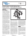 1
1
-
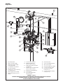 2
2
-
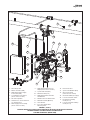 3
3
-
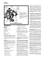 4
4
-
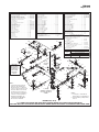 5
5
-
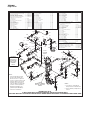 6
6
-
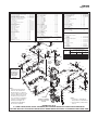 7
7
-
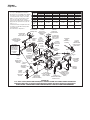 8
8
-
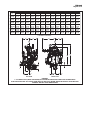 9
9
-
 10
10
-
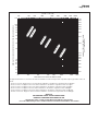 11
11
-
 12
12
-
 13
13
-
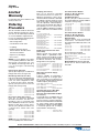 14
14


Ask a question and I''ll find the answer in the document
Finding information in a document is now easier with AI
Related papers
Other documents
-
Johnson Controls Tyco DV-5a Series User manual
-
Ames Fire & Waterworks 933GS Installation guide
-
Rain Bird HVF Installation guide
-
Rain Bird HVF Installation guide
-
Reliable Single Interlock Preaction System Specification
-
System Sensor WFDNA Series Installation And Maintenance Instruction
-
Potter CoilKeeper Owner's manual
-
Toro 730 User manual
-
Honeywell Switches User manual
-