4090-9005, -9006
Suppression Release Peripheral
Application and Installation Instructions
2008-2017 Tyco Fire Protection Products. All rights reserved.
Specifications and other information shown were current as of publication and are subject to change without notice.
TYCO, SIMPLEX, and the product names listed in this material are marks and/or registered marks. Unauthorized use is strictly prohibited.
579-385
Rev. N
READ AND SAVE THESE INSTRUCTIONS. Follow the instructions in this
installation manual. These instructions must be followed to avoid damage to this product
and associated equipment. Product operation and reliability depend upon proper
installation.
DO NOT INSTALL ANY SIMPLEX
®
PRODUCT THAT APPEARS DAMAGED.
Upon unpacking your Simplex product, inspect the contents of the carton for shipping
damage. If damage is apparent, immediately file a claim with the carrier and notify an
authorized Simplex product supplier.
ELECTRICAL HAZARD. Disconnect electrical field power when making any internal
adjustments or repairs. All repairs should be performed by a representative or authorized
agent of your local Simplex product supplier.
STATIC HAZARD. Static electricity can damage components. Handle as follows:
Ground yourself before opening or installing components.
Prior to installation, keep components wrapped in anti-static material at all times.
When the Suppression Release Peripheral (SRP) is used for field replacement, no action is
necessary. In a new installation, the software limitations in Table 1 must be adhered to.
This is because revision E and earlier SRPs sensed only normal (10 k EOL) and trouble
(open-circuit) conditions, and revision F and later SRPs sense normal (10 k EOL),
trouble (open-circuits), and supervisory (16.2 k disconnect switch) conditions. When
adding a SRP to an existing (pre-revision F) installation, it is necessary to either upgrade
the software or clip the 16.2 k resistor from the maintenance switches
Table 1. SRP Compatibility Information
4010
- SRP is compatible with 4010 IDNet and NACs
- Master software is at revision 4.01* or higher
- SFIO software is at revision 4.01* or higher
4009
- SRP is compatible with 4009 IDNet and NACs
4100U
- SRP is compatible with 4100 IDNet and NACs on the following:
SPS,RPS, XPS and XNAC (not XSIG)
- Master software is at revision 11.11* or higher
SPS is at revision 3.07* or higher
- IDNET and IDNET+ are at revision 3.07* or higher
4007ES and 4007ES Hybrid
- Software Revision 3.03 or higher
4010ES
- All revisions
- SRP is compatible with IDNet or IDNet2 and MSS(I) or ESS
4100ES
- All revisions
- SRP is compatible with IDNet or IDNet2 and SPS, or EPS, or RPS, or
XPS, or XNAC (all software revisions).
- SRP is not compatible with XSIG
* These revisions incorporate the capability to interpret the additional line condition, which is the
16.2 k supervisory resistor.
This publication describes the installation procedure for the 4090-9005 and 4090-9006
SRP. The SRP controls the actuator that activates the suppression release systems (such as
CO
2
or INERGEN), single or double interlock preaction sprinkler systems, and deluge
sprinkler systems.
With the SRP, you can upgrade the FACP to enable it to become an agent release system,
see Figure 1. Appropriate software is required.
Continued on next page
Cautions and
Warnings
Important Compatibility
Information
Introduction

Suppression Release Peripheral Application and Installation Instructions
2
Figure 1. Suppression Release Peripheral
Note: The IDNet channel supports address codes 1 through 250.
Each SRP has a unique address. The address of the SRP is set with an eight position dip
switch (Figure 1), DIP switch position 1 is the least significant bit (LSB) and position 8 is
the most significant bit (MSB). Set the address using Figure 2 as reference. Use a small
screwdriver or pen to set the switches. Write the device address for the SRP on the re-
sealable label, this information aids in troubleshooting the system.
Note: DIP switch in 1 position is ON while DIP switch in 0 position is OFF.
FigureTag FD9-385-01
0000 1000 0100 1100 0010 1010 0110 1110 0001 1001 0101 1101 0011 1011 0111 1111
0000
0 16 32 48 64 80 96 112 128 144 160 176 192 208 224 240
1000
1 17 33 49 65 81 97 113 129 145 161 177 193 209 225 241
0100
2 18 34 50 66 82 98 114 130 146 162 178 194 210 226 242
1100
3 19 35 51 67 83 99 115 131 147 163 179 195 211 227 243
0010
4 20 36 52 68 84 100 116 132 148 164 180 196 212 228 244
1010
5 21 37 53 69 85 101 117 133 149 165 181 197 213 229 245
0110
6 22 38 54 70 86 102 118 134 150 166 182 198 214 230 246
1110
7 23 39 55 71 87 103 119 135 151 167 183 199 215 231 247
0001
8 24 40 56 72 88 104 120 136 152 168 184 200 216 232 248
1001
9 25 41 57 73 89 105 121 137 153 169 185 201 217 233 249
0101
10 26 42 58 74 90 106 122 138 154 170 186 202 218 234 250
1101
11 27 43 59 75 91 107 123 139 155 171 187 203 219 235
0011
12 28 44 60 76 92 108 124 140 156 172 188 204 220 236
1011
13 29 45 61 77 93 109 125 141 157 173 189 205 221 237
0111
14 30 46 62 78 94 110 126 142 158 174 190 206 222 238
15 31 47 63 79 95 111 127 143 159 175 191 207 223 239
LSB
MSB
1 2 3 4 5 6 7 8
1111
DIP SWITCHES 5 THRU 8
ON
OFF
1 = ON 0 = OFF
251
252
253
254
255
DIPSWITCH IS SHOWN SET AT ADDRESS 7.
Figure 2. Suppression Release Peripheral Address Chart
Introduction
Setting the SRP
Address
ADDRESS SWITCH
(SW1)
BRACKET
ASSEMBLY
SUPPRESSION
RELEASE MODULE
RAC OUTPUT
(TB2)
NAC INPUT
(TB1)
LED HARNESS
PLUG (P1)
IDNet INPUT
(TB3)

Suppression Release Peripheral Application and Installation Instructions
3
Refer to the 2975-9227 enclosure installation instructions (579-403) for mounting the
enclosure box.
Follow the directions below to mount the 4090-9005 and 4090-9006 SRP to a 2975-9227
Enclosure (See Figure 3).
Note: The 4090-9006 ULC-listed SRP is shipped with the peripheral already mounted to the
enclosure, skip step 1 for the 4090-9006.
The 4090-9005 SRP mounting orientation must be with the NAC and IDNet terminals on the
left as illustrated in the figure below.
1. Secure the SRP with bracket assembly to the four enclosure, threaded mounting studs
using the four supplied nuts (do not over tighten).
2. The SRP has an optional communications LED option kit (4090-9812) that mounts to
the cover. If using the LED option kit, remove the plastic snap-in plug on the
enclosure box cover. The LED snaps into the hole on the sheet metal cover. Connect
the LED harness to connector P1 on the SRP and ensure red goes on top.
3. Perform all SRP field wiring and optional LED wiring using the wiring information in
Tables 2 and 3. Use Figure 4 and Figure 5 as a reference.
4. Secure the cover to the enclosure box by tightening the captive flat head screw on the
cover (do not over tighten).
Figure 3. SRP 2975-9227 Enclosure Mounting
Mounting the SRP
2975-9227 RED ENCLOSURE BOX
4090-9005, -9006 SUPPRESSION
RELEASE PERIPHERAL &
MOUNTING BRACKET ASSEMBLY
NUTS QTY: 4
(SUPPLIED with ENCLOSURE)
MOUNTING STUDS (4) FOR SRP
MOUNTING

Suppression Release Peripheral Application and Installation Instructions
4
IDNet Input
The SRP communicates with the FACP through the IDNet channel. The IDNet channel
connects to terminal TB3 on the SRP and accepts two 12 – 18 AWG wires on each of the
terminals.
An IDNet circuit has a communications power rating of 36.25 volts (maximum) at .5 A,
3333 baud.
NAC Input
Note: Only SRP is allowed per NAC, no EOL supervision resistor is required on the NAC. The
Releasing Appliance Circuit (RAC) supervision module must be wired to the RAC output for
proper NAC supervision.
The SRP NAC Input monitors the NAC from the FACP. The NAC interface monitors the
NAC for NO POWER, SUPERVISION, and ACTIVE states. The NAC Input connects to
terminal TB1 on the SRP and accepts two 12 – 18 AWG wires on each of the terminals.
See Table 2 for maximum NAC wiring distance calculations. Refer to NAC wiring
diagrams for more details.
Releasing Appliance Circuit (RAC) Output Interface
The SRP monitors the output RAC wiring for opens and shorts. It will NOT monitor the
coil. A coil supervision module (2081-9046) must be placed as close to the coil as possible
to monitor the wiring. The RAC device connects to terminal TB2 on the SRP and accepts
up to 12 AWG wiring.
Due to the variety of actuators that can be used with this releasing device, the
minimum allowable voltage at the end of the RAC wiring is 20.4 V DC. Line distances
must be calculated assuming a maximum voltage drop of 0.6 V (minimum SRP output –
coil supervision module – minimum actuator voltage; 21.7-.7-20.4) at the rated actuator
operating current, including the coil supervision module. See Table 3 for maximum RAC
wiring guidelines and distance calculations.
Table 2 provides the maximum NAC input wiring distances to the Suppression Release
Peripheral (SRP). The maximum distances are based on the actuator current draw, wire
gauge and total line resistance. The SRP provides a single Releasing Appliance Circuit
(RAC) to control the releasing actuator and a DC to DC regulator to ensure proper voltage
is supplied to the actuator. Due to the efficiency of the DC to DC regulator, the dedicated
NAC used to power the SRP must be rated at 2 amps for actuator loads up to 1 amp, or
3 amps for actuator loads greater than 1 amp up to 2 amps maximum. For actuator loads
up to 1.75 amps the maximum wiring distances are based on a total voltage drop of 3.4 V.
For 2 amp actuator loads the maximum wiring distance is based on a total voltage drop of
1.2 V.
Table 2. SRP NAC Wiring Distances
MAXIMUM NAC WIRING DISTANCES
Based on a total Drop of 3.4 V
RAC OUTPUT
CURRENT
(Refer to actuator
rating)
DISTANCE
TOTAL LINE
RESISTANCE
18 AWG
16 AWG
14 AWG
12 AWG
0.50 A
250’
399’
635’
1,010’
3.58
0.75 A
167’
266’
423’
673’
2.39
1.00 A
125’
199’
317’
505’
1.79
1.25 A
1
100’
159’
254’
404’
1.43
1.50 A
1
84’
133’
212’
337’
1.19
1.75 A
1
72’
114’
181’
289’
1.02
2.00 A
1,2
25’
39’
63’
100’
0.36
1
For RAC Output greater than 1.0 A, NAC must be at least 3 A Capacity
2
2.0 A RAC Output Line Distance is based on Total Drop of 1.2 V, NOT 3.4 V
SRP Terminal
Wiring
Inputs/Outputs
Wiring
Restrictions
Continued on next page

Suppression Release Peripheral Application and Installation Instructions
5
Table 3. SRP RAC Wiring Guidelines
MAXIMUM RAC WIRING DISTANCE
Based on a total Drop of 0.6 V
RAC OUTPUT
CURRENT
(Refer to
actuator rating)
DISTANCE
TOTAL LINE
RESISTANCE
18 AWG
16 AWG
14 AWG
12 AWG
0.50 A
74’
118’
188’
300’
1.06
0.75 A
50’
79’
126’
200’
0.71
1.00 A
37’
59’
94’
150’
0.53
1.25 A
30’
47’
75’
120’
0.43
1.50 A
25’
39’
63’
100’
0.35
1.75 A
21’
34’
54’
85’
0.30
2.00 A
19’
30’
47’
75’
0.27
The SRP RAC outputs are designated on the printed circuit board as RAC+ and RAC-.
The SRP RAC must connect to a 2081-9046-coil supervision module, which in turn
connects to a 12 V DC or 24 V DC actuator (see Figure 4). It can also connect to the
maintenance switches listed in Table 4. See Figure 5 for a connections diagram with a
maintenance switch.
All wiring must be 18 AWG (minimum) to 12 AWG (maximum).
Conductors must test free of all grounds.
All wiring is supervised and power limited unless otherwise noted.
Wiring between 2081-9046-coil supervision modules (Yell/Black) is not power limited.
Refer to the 2081-9046 Coil Supervision Module Wiring Instructions (574-437).
Connect 24 V DC actuator as shown, only one 24 V DC actuator per RAC +, - output.
Connect the 12 V DC actuator as shown. Two units must be connected through a
maximum of 20 feet in conduit.
For specific actuator wiring instructions, refer to the manufacturer’s recommendations.
For UL/ULC application, the RAC is a special application circuit, and must only be
used with the actuators listed in Table 5.
The RAC is compatible for use with any FM approved electric release deluge,
pre-action and refrigerated area sprinkler solenoid valve rated 22 watts or less. Refer
to the solenoid valve manufacturer’s product documentation for verification of agency
listings and power requirements.
Maximum alarm current is 2 A.
Earth Fault Detection on RAC is 2 kOhms or less.
Table 4. Maintenance and Abort Switches
PID
Description
2080-9056
Abort Switch Flush
2080-9057
Abort Switch Surface
2080-9067
Abort Switch Style C Flush
2080-9068
Abort Switch Style C Flush
2080-9059
Maint Switch w/Lamp Flush
2080-9060
Maint Switch w/Lamp Surface
Continued on next page
Wiring
Restrictions
Wiring Guidelines

Suppression Release Peripheral Application and Installation Instructions
6
Table 5. UL/ ULC Compatible Releasing Devices
MFG
NOTES
ANSUL
AUTOMAN II-C Assembly (uses solenoid 17728; coil 25924)
AUTOMAN II-C Explosion-Proof Releasing Device
(uses solenoid 31492; coil 31438)
AUTOMAN II-C Assembly (uses solenoid 68739; coil 25924)
Solenoid Electric Actuator (uses solenoid 73111; coil 73097)
CV90 HF Electric Actuator 73327 (may use 73606 in-line resistor)
LP CO2 w/ASCO solenoid 422934
LP CO2 double action 24 V solenoid 430948
LP CO2 3-way selector valve solenoid 433419
Electric Actuator – 24 VDC solenoid 570537
LPG
Solenoid Electric Actuator (uses solenoid: Flow Control 609500/671S)
Solenoid Coupling Assembly 21006401 (uses solenoid: Flow Control 609500/671S)
Solenoid Coupling Assembly 21006402 (uses solenoid: Flow Control 609500/671S)
LPG128/145/190/230-50/55 FM-200 valves (uses solenoid: Flow Control 609500/671S)
LPG128-90UL iFLOW and FM-200 valve (uses solenoid: Flow Control 609500/671S)
ASCO
Model 8210A107 (097617-005D coil) ½ in. NPS, 5/8 in. orifice. 24 VDC
Model 8210G207 (238310 coil) ½ in. NPS, ½ in. orifice.
Model 8211A107 (097617-005D coil) 24 VDC
Model 8262H182
Model EF8210G001MBMO
Model HV2628571 (23810 coil) N.C. ½ in. NPS, ½ in. orifice.
Model HV2648581 (23810 coil) N.O. ½ in. NPS, 1.2 in. orifice.
R8210A107 (097617-005D coil) ½ in. NPS, 5/8 in. orifice.
T8210A107 (097617-005D coil) ½ in. NPS, 5/8 in. orifice.
Hygood
(TSP)
Model 304.205.010 – Electrical Actuator Suppression diode
Model 304.209.001 – Electrical Actuator Bridge Rectifier
PyroChem
ECH Electrical Control Head (551201)
Explosion-Proof Electric Actuator (570147)
Removable Electric Actuator (570209) 0.2 A
Skinner
Model 71395SN2ENJ1NOH111C2 (Skinner coil H111C2) 1/4 in. NPS, 1/16 in.
Model 73212BN4TN00NOC111C2 (Skinner coil C111C2) ½ in., 5-300 psi
Model 73212BN4TNLVNOC322C2 (Skinner coil C322C2) ½ in. NPS, 0.92 A, 250 psi
Model 73218BN4UNLVNOH111C2 (Skinner coil H111C2)
Model 73218BN4UNLVNOC111C2 (Skinner coil C111C2) ½ in. NPW, 5/8 in. orifice.
Burkert
Model 5282 2/2 – Way Solenoid Valve
Minimax
Model MX1230 without diode, 24V DC, ½ in. NPT
Versa
Model CGS-4292-NB3-S20000
Table 6. Battery Calculation Guidelines
Condition
Current
Standby
0 mA*
Alarm
Refer to Table 6 Below
*= The SRP and coil supervision module looks like a 10k EOL resistor, which is
already figured into FACP standby current requirements. No additional standby
calculations are required when connecting an SRP to a FACP.
To use the table, first refer to actuator’s current rating. Then, determine the amount of
alarm current required from the NAC to supply the actuator. Use this figure to determine
alarm current battery requirements. For example, a 1.0 A actuator would require 1.71 A
alarm current from the FACP.
Continued on next page
Wiring Guidelines
(continued)
Standby Battery
Calculations

Suppression Release Peripheral Application and Installation Instructions
7
Table 7. SRP
RAC CURRENT
ALARM CURRENT REQUIRED FROM NAC
0.5 A
854 mA
0.75 A
1.28 A
1.0 A
1.71 A
1.25 A
2.14 A
1.5 A
2.56 A
1.75 A
3.0 A
2.0 A*
3.0 A
NAC INPUT FROM
FACP/NAC
EXTENDER
IDNet INPUT
FROM FACP
NAC -
NAC +
IDNet +
IDNet -
TO NEXT DEVICE
SEE
NOTE 1
BLK
RED
(ONE 24 V UNIT
PER CIRCUIT)
K
L
B
YEL
COIL
SUPERVISION
MODULE
24 V
ACTUATOR
NAC INPUT FROM
FACP/NAC
EXTENDER
IDNet INPUT
FROM FACP
NAC -
NAC +
IDNet +
IDNet -
TO NEXT DEVICE
SEE
NOTE 1
BLK
RED
COIL
SUPERVISION
MODULE
12 V
ACTUATOR
12 V
ACTUATOR
K
L
B
YEL
COIL SUPERVISION MODULE
2081-9046 LOCATED IN
VALVE JUNCTION BOX
RAC -
RAC +
IDNET +
IDNET -
TB3
TB1
TB2
RAC -
RAC +
TB1
TB3
TB2
IDNET +
IDNET -
P1 Red Black
P1 Red Black
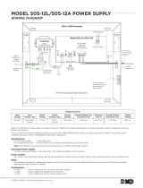
Notes:
1. Refer to Table 3 for maximum RAC wiring distance based on 0.6 V Drop, including supervision module. 0.6 V Drop per
Releasing Appliance Circuit (RAC) Output Interface description is on page 5 and Table 3. RAC wiring is class B only.
2. When connecting two wires to one terminal, position one wire on each side of the terminal screw.
3. IDNet, NAC, and RAC lines are 18 AWG (minimum) to 12 AWG (maximum).
4. Refer to the appropriate FACP instructions for IDNet and NAC wiring guidelines.
Figure 4. SRP Wiring
Continued on next page
Standby Battery
Calculations,
continued
SRP Wiring
*2.0 A rating is the same as 1.75 A rating

Suppression Release Peripheral Application and Installation Instructions
8
-385-02
Notes:
1. Connect the black wire to black and the red wire to red on the coil supervision module.
2. Refer to Table 3 for maximum RAC wiring distance based on 0.6 V, including supervision module. 0.6 V
Drop per Releasing Appliance Circuit (RAC) Output Interface description is on page 5 and Table 3. RAC
wiring is class B only.
3. When connecting two IDNet wires to one terminal, position one wire on each side of the terminal screw.
4. If a maintenance switch without a lamp (2080-9069, 2080-9070) is used, an auxiliary power source is not
needed.
Figure 5. Connections to Maintenance Disconnect Switch
Maintenance
Switch Wiring

Suppression Release Peripheral Application and Installation Instructions
9
For systems intended for Halon 1301 (NFPA 12A), Halon 1211 (NFPA 12B), or clean
agents (NFPA 2001) release, a pre-discharge NAC must be configured to warn building
occupants of the impending discharge. Refer to the applicable control panel programming
manual (574-849 for 4100U/4100ES/4010ES, 579-1167 for 4007ES and 574-052 for
4010) for programming details. Compliance with ADA requires audible and visible
notification.
Use of abort switches in a pre-action or deluge water type releasing service will void UL
864 Listing for this product and for the associated fire alarm control panel.
Program an addressable monitor point for abort operation by following the programming
details in the applicable manual. When the abort switch is activated, the control panel
halts the release or discharge of extinguishing agent. Pressing and holding the abort switch
will prevent agent release/discharge unless the manual release switch is activated. Manual
release overrides abort.
Activation of a manual release switch is indicated with a programmed red manual release
LED on the FACP. Upon activation of the manual release switch, the system will activate
the applicable releasing circuits upon expiration of the manual release timer or upon
expiration of a previously active automatic release timer if the remaining time on the
automatic release timer is less than the programmed manual release timer.
Note: Setting the manual release timer to zero will result in immediate release.
Suppression
Release
Application
Requirements
Abort Switches

FM System Requirements
579-385
Rev. N
This section describes specific requirements for Factory Mutual agent release and
preaction/deluge systems.
Use battery calculations for battery voltage to 23 V DC minimum.
Use Coil Supervision Module 2081-9046 on each releasing circuit.
Release circuit voltages must remain between 20.4 V DC and 26.4 V DC under all
load conditions. Follow wiring chart to determine maximum wiring distance from
panel to releasing appliances.
The RAC is compatible for use with any FM approved electric release deluge,
pre-action and refrigerated area sprinkler solenoid valve rated 22 watts or less.
Refer to the solenoid valve manufacturer’s product documentation for
verification of agency listings and power requirements.
Initiating device circuits must be wired Class A.
Battery standby must be 90 hours.
Release circuit voltages must remain between 20.4 V DC and 26.4 V DC under
all load conditions. Refer to Table 3 to determine maximum wiring distance
from panel to releasing appliances.
Introduction
General
Automatic
Extinguishing
Release
Requirements
Preaction/Deluge
Applications
/