Page is loading ...

4901 TrueAlert
®
Non-Addressable Horn
Installation Instructions
CAUTION: When switch SW1 is in the
SmartSync mode, the horn will not
operate unless connected to a
SmartSync control module (4905-
9938), 4010 fire alarm control panel,
or 4009 IDNet NAC extender. The
factory default setting for SW1 is
“OFF.”
Cautions and Warnings
READ AND SAVE THESE INSTRUCTIONS- Follow the instructions in this installation manual. These
instructions must be followed to avoid damage to this product and associated equipment. Product operation
and reliability depend upon proper installation.
DO NOT INSTALL ANY SIMPLEX
®
PRODUCT THAT APPEARS DAMAGED- Upon unpacking your
Simplex product, inspect the contents of the carton for shipping damage. If damage is apparent, immediately
file a claim with the carrier and notify an authorized Simplex product supplier.
ELECTRICAL HAZARD- Disconnect electrical field power when making any internal adjustments or repairs.
All repairs should be performed by a representative or authorized agent of your local Simplex product
supplier.
STATIC HAZARD- Static electricity can damage components. Handle as follows:
• Ground yourself before opening or installing components.
• Prior to installation, keep components wrapped in anti-static material at all times.
FCC RULES AND REGULATIONS – PART 15- This equipment has been tested and was found to comply with the limits
for a Class A digital device pursuant to Part 15 of the FCC Rules. These limits are designed to provide reasonable
protection against harmful interference when the equipment is operated in a commercial environment. This equipment
generates, uses, and can radiate radio frequency energy and, if not installed and used in accordance with the instruction
manual, may cause harmful interference to radio communications. Operation of this equipment in a residential area is
likely to cause harmful interference in which case the user will be required to correct the interference at his own expense.
SAFETY OF NOTIFICATION APPLIANCES - Always install, maintain, and test notification appliances within their
specifications. Failure to follow all safety precautions and instructions may result in loss of life and property due to non-
functioning notification appliances.
Some notification appliances use high voltage. To avoid electrical hazards and damage to appliances, make sure that the electrical
power for the notification appliance circuit is disconnected at the control panel. Disconnect before installing, repairing, or internally
adjusting any notification appliances.
Even with electrical power removed, some notification appliances store a high voltage charge. This high voltage can cause injury
resulting in death from electrical shock. DO NOT TOUCH EXPOSED CIRCUITRY.
The 4901-6820 and 4901-9820 TrueAlert horn (see Figure 1) is
a non-addressable wall-mounted notification appliance that
provides an audible indication of an alarm condition. It is
activated from the control panel of a UL-listed, Simplex fire
alarm system. When the notification appliance emits sound,
it indicates the possibility of an emergency situation that
requires your immediate attention.
The horn is a notification appliance that operates on a reverse
polarity notification appliance circuit (NAC). When this NAC
circuit is in the reverse polarity, or supervision state, the horn
does not operate, and introduces high impedance to the circuit.
The horn operates when the NAC changes polarity, to enter the
“alarm” state.
When the horn powers up, it checks the setting of the Switch
(SW1) to determine whether to operate in either Free-Run
(SW1 “OFF”) or SmartSync
(SW1 “ON”) Mode. If the
switch is set for Free-Run mode, the horn sounds for as long
as power is applied. Otherwise, the horn waits in silence for
commands from the NAC.
When set for SmartSync mode, the horn responds to Turn-
ON, Turn-OFF, March Time, and Temporal command
signals received from the SmartSync circuit. The horn
responds immediately on any valid command received to reset the sounder operation to the new mode. The horn will
produce an audible, ½ second pulse every 1.0 second when either March Time or Temporal command is detected, with
every fourth pulse removed, under the Temporal (Code 3) command. See Table 1 for information about sound output
levels and current draw on the TrueAlert horn.
TrueAlert
Non-
Addressable
Horn
Operation
Figure 1. TrueAlert Horn
© 2005-2015 Tyco Fire Protection Products. All rights reserved. All specifications and other information shown were current as of document revision date and are subject to change without
notice.
Tyco, Simplex, and the product names listed in this material are marks and/or registered marks. Unauthorized use is strictly prohibited.
574-720
Rev. G

4901 TrueAlert Non-Addressable Horn Installation Instructions
WARNING: Make sure that all power is disconnected before starting the installation.
CAUTION: Connect the wiring to terminals as shown. Do not loop wires under the terminals. Break the
wire runs to provide supervision of connections. Strip the lead insulation to a maximum of 3/8-inch
(9.5 mm).
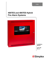
1. At the enclosure box, connect the contractor wires to the NAC+ and NAC- terminals at the rear of the horn unit. See
Figure 2.
2. When connecting more than one horn to a circuit, ensure that correct polarity is maintained for each unit.
3. When connecting the last horn on a circuit, connect an end-of-line resistor (EOLR) to the horn terminals.
TrueAlert Horn (Rear View)
Figure 2. TrueAlert Horn Wiring
TrueAlert
Non-
Addressable
Horn Wiring
Notes:
1. Notification appliances are rated per individual nameplate label.
2. Maintain correct polarity on the terminal connections.
3. Refer to the field wiring diagrams supplied with the FACP for detailed NAC wiring information.
4. These appliances were only tested to the operating voltage limits of 16 VDC and 33 VDC. Do not
operate these appliances outside these limits, as this can cause the appliance to fail to operate, and/or
cause permanent damage to this equipment.
NAC+ TERMINAL
NAC- TERMINAL
NAC TERMINALS ACCEPT
2 WIRES: #12 - #18 AWG
16-33 VDC POWER INPUT
(See Note 4)
PRODUCT ID
NAMEPLATE LABEL
IF LAST APPLIANCE
ON CIRCUIT,
CONNECT EOLR
(See Notes)
16-33 VDC FROM
NOTIFICATION APPLIANCE
CIRCUIT OR PRECEEDING
APPLIANCE
(See Notes)
2

4901 TrueAlert Non-Addressable Horn Installation Instructions
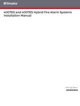
See Figure 3 for mounting the TrueAlert horn to the enclosure box. When surface mounting the horn (4905-9937
or 4905-9940
), a surface mount skirt is recommended. Refer to the 4905 TrueAlert NAC Surface Mount Skirt
Installation Instructions (574-790) for this mounting application.
Tighten mounting screws snugly (careful not to overtighten).
For semi-flush mounting, install the box, either flush with the wall, or with a maximum recess of 0.25-inch (6.35 mm).
Figure 3. TrueAlert Horn Mounting
Mounting the
TrueAlert
Non-
Addressable
Horn
BOTTOM OF UNIT
SEE NOTE 4
4-INCH (102 mm)
SQUARE
ELECTRICAL BOX
NOT SUPPLIED
HORN COVER
HOUSING
SWITCH SW1 (RECESSED IN HOUSING)
OFF = FREE-RUN MODE (SHOWN)
ON = SmartSync
MODE
(See Note 3)
NAC + and NAC - TEST
POINTS
(See Note 3)
TABS FIT INTO
SLOTS ON THE
INSIDE OF THE
HORN COVER
Notes:
1. The TrueAlert horn attaches directly to standard single-gang, double-gang, or 4-inch (102 mm) square electrical
box (not supplied) mounted semi-flush, or surface to the wall’s surface.
2. There are two holes for single-gang, and four holes for double-gang electrical box mounting. Secure the housing
to the single-gang or double-gang box using two mounting screws (#6/ 32 x 1 1/8-inch (35 mm) long, not
supplied). The two mounting screws are placed cross corner (opposite top and bottom holes) on the double-gang
installation. Mounting the horn to the 4-inch (102 mm) square electrical box is shown.
3. Switch SW1, NAC+ and NAC– test points are accessible after mounting with the horn cover removed.
4. To remove cover, depress snap release with a flat tip screwdriver while pulling up cover with your other hand.
DOUBLE-GANG
MOUNTING HOLES
(See Note 2)
SCREWS FROM 748-472
SHIP GROUP QTY: 2
(MOUNT SCREWS
CROSS CORNER)
4-INCH (102 mm)
SQUARE
MOUNTING HOLES
(See Notes 1 and 2
)
DOUBLE-GANG
MOUNTING HOLES
(See Notes 1 and 2)
SINGLE-GANG
MOUNTING HOLES
SmartSync
ON
Free-Run
4-INCH (102 mm)
SQUARE
MOUNTING HOLES
(See Note 2)
3

85
86
87
88
89
90
91
92
93
94
95
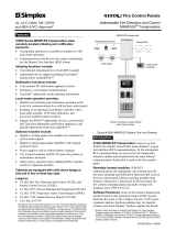
90 80 70 60 50 40 30 20 10 0 10 20 30 40 50 60 70 80 90
Angular Displacement (Degrees) on Horizontal Axis
Sound Pressure Level (dB) at 10 ft (3 m)
96
4901 TrueAlert Non-Addressable Horn Installation Instructions
Table 1. TrueAlert Horn Sound Pressure Level Measurements
VOLTAGE
(VDC)
CURRENT
(mA)
HORN MODE
(See Note 1)
SOUND PRESSURE MEASUREMENT (dBA)
ANECHOIC ROOM
AVERAGE AT TEN FEET
(See Note 2)
REVERBERANT ROOM AT
TEN FEET PER UL464
(See Note 3)
16
(Minimum)
21
Steady
93
86
Coded
89
83
24
(Nominal)
23
Steady
96
89
Coded
92
85
33
(Maximum)
27
Steady
96.3
92
Coded
92.3
88
Notes:
1. The coded category covers both Temporal and March Time
cadences.
2. Average anechoic dBA measurements are measured on the axis in a
non-reflective test chamber using fast meter response.
3. Reverberant dBA measurements are a minimum UL rating based on
sound power level measurements made in UL’s reverberant test
chamber.
4. Refer to Figure 4 for directional characteristics.
5. When used with the STI Model STI-1210D (with a flush or surface
mounted backbox) Vandal Guard, the sound output is reduced 3.1
and 6.1 dBa respectively. The guard is not listed for ULC
applications.
Notification Appliances, and the fire alarm system itself, have certain limitations and requirements for placement,
installation, and test (details on safety can be found on page 1). Since you must know the limitations and adhere to
the requirements, keep these instructions at a central location for future reference so that all people who use,
maintain, and test the fire alarm system have access to this information.
Notification appliances do not sense any hazardous conditions such as smoke, fire, or explosion. They are
activated by a control panel, as part of a system that does sense such conditions.
Notification appliances do not provide their own power. They receive their power from the fire alarm system.
If power is not supplied to the notification appliances (for whatever reason), their audible warnings will not
sound. THEREFORE, BACK-UP POWER SUPPLIES, OR OTHER BACK-UP POWER SOURCES ARE
REQUIRED FOR THE FIRE ALARM SYSTEM.
Notification appliances provide a specific rated output level of sound. The output level must meet the
requirements of the intended protected area(s). Although the 4901 TrueAlert horn notification appliance meets
the current UL standards for sound, the protected area(s) may have walls, doors, carpeting, furniture, insulation,
or other obstacles that reduce or even block the sound. For all applications, the sound output must provide
enough intensity to alert all occupants of the protected area(s), including those occupants that are sleeping or
hearing impaired for whatever reason. If these occupants cannot hear the notification appliances within the
protected area(s), you must increase the intensity of the sound output or add additional notification appliances so
that the occupants can hear the notification appliances when have been activated. Refer to Chapter 6 of the
National Fire Protection Association (NFPA) National Fire Alarm and Signaling Code 72 (2002 Edition).
Notification Appliances are not a substitute for insurance coverage. All users should have adequate levels of life
and property insurance.
The placement of notification appliances must conform to:
• Latest NFPA standards and guidelines (Refer to National Fire Alarm and Signaling Code 72, 2002 Edition,
Chapter 6)
• Sound (sound pressure level) analysis of intended protected areas
• Local authority having jurisdiction (AHJ) requirements
Notification appliances are not intended for installation within hazardous locations as defined by the National Electrical Code (NEC) or the
NFPA. Contact Simplex for information on explosion-proof notification appliances designed for hazardous environments.
Sound Pressure
Level
Measurements
Limitations and
Placement of
Notification
Appliances
Limitations
Placement
Figure 4. TrueAlert Non-Addressable Horns,
Directional Characteristics FigureTag FD4-720
574-720
Rev. G
/