CT terminals are referenced to the meter’s neutral and may be at elevated voltages.
TO AVOID DEATH OR SERIOUS PERSONAL INJURY:
• Do not contact meter terminals while the unit is connected
• Do not connect or short other circuits to the CT terminals
WARNING
For all Series 4100 meters, CTs are polarity sensitive.
Observe orientation.
NL1
X2
X1
White
Black
A
B
C
N
X1
X2
X1
X2
X1
X2
A
B
C
Diagram 1:
1-Phase Line-to-Neutral 2- Wire System 1 CT
Diagram 2:
1-Phase Line-to-Line 2-Wire System 1 C
L1 L2
X2
X1
A
B
C
N
A
B
C
White
Black
X1
X2
X1
X2
X1
X2
Use System Type 11 (2L)Use System Type 10 (1L + 1n)
L1 L2
X2
X1
X2
X1
A
B
C
N
A
B
C
N
White
Black
White
Black
X1
X2
X1
X2
X1
X2
Diagram 3:
1-Phase Direct Voltage Connection 2 CT
L1 L2 L3
X2
X1
A
B
C
N
A
B
C
X2
X1
X2
X1
White
Black
White
Black
White
Black
X1
X2
X1
X2
X1
X2
Diagram 4:
3-Phase 3-Wire 3 CT no PT
Use System Type 12 (2L + 1n) Use System Type 31 (3L)
L1NL2L3
X2
X1
A
B
C
N
A
B
C
X2
X1
X2
X1
White
Black
White
Black
White
Black
X1
X2
X1
X2
X1
X2
Diagram 5:
3-Phase 4-Wire Wye Direct Voltage Input Connection
3 CT
Use System Type 40 (3L + 1n)
White
Black
White
Black
White
Black
L1NL2L3
X2
X1
A
B
C
N
A
B
C
X2
X1
X2
X1
X1
X2
X1
X2
X1
X2
Diagram 6:
3-Phase 4-Wire Wye Connection 3 CT 3 PT
Use System Type 40 (3L + 1n)
WIRING
CONTROL POWER
SOLID STATE PULSE OUTPUTS (S4100-K)
Direct Connect Control Power
(DC Control Power)
L1NL2L3
12G
L1NL2L3
12G
L1
12G
L2 L3
Direct Connect Control Power
(Line to Neutral)
Line to Neutral from 90 Vac to 347 Vac (UL) or 300 Vac (CE)
12G
Control Power Transformer (CPT) Connection
Direct Connect Control Power
(Line to Line)
Line to Line from 90 Vac to 600 Vac (UL). In UL installations the lines may
be floating (such as a delta). If any lines are tied to an earth (such as a
corner grounded delta), see the Line to Neutral installation limits. In CE
compliant installations, the lines must be neutral (earth) referenced at
less than 300 Vac
L-N
The Control Power Transformer may be wired L-N or L-L. Output to meet
meter input requirements
DC Control Power from 125 Vdc to 300 Vdc (UL and CE max.)
Fuse Recommendations:
Keep the fuses close to the power source (obey local and national code requirements).
For selecting fuses and circuit breakers, use the following criteria:
• Select current interrupt capacity based on the installation category and fault current
capability.
• Select over-current protection with a time delay.
• Use a voltage rating sufficient for the input voltage applied.
• Provide over-current protection and disconnecting means to protect the wiring. For
DC installations, provide external circuit protection. Suggested: 0.5 A, time delay
fuses rated for DC operation at or above the supply voltage.
• Use the earth connection (G) for electromagnetic compatibility (EMC), not a
protective earth ground.
Use this section to enter:
• Modbus or BACnet communication parameters
• CT (Current Transducer) input current ranges
• The service type to be monitored
These instructions assume the meter is set to factory defaults. If it has been previously
configured, all optional values should be checked. For more options (i.e., potential
transformer ratios, etc.) and the full setup instructions, see the full installation guide for the
specific model at www.leviton.com.
The Series 4100-K has one normally open (N.O.) KY Form A output and one normally
closed (N.C.) output. One is dedicated to energy (Wh), and the other to alarm.
Daisy-chaining Devices to the Power Meter
The RS-485 slave port allows the power meter to be connected in a daisy chain with up to
63 two-wire devices.
In this bulletin, communications link refers to a chain of devices that are connected by a
communications cable.
NOTES:
• The terminal’s voltage and current ratings are compliant with the requirements of the
EIA RS-485 communications standard.
• The RS-485 transceivers are ¼ unit load or less.
• RS-485+ has a 47 k1 pull-up to +5V, and RS-485- has a 47 k1 pull-down to Shield
(RS-485 signal ground).
• Wire the RS-485 bus as a daisy chain from device to device, without any stubs.
Use 120 1 termination resistors at each end of the bus (not included).
• Shield is not internally connected to Earth Ground.
• Connect Shield to Earth Ground somewhere on the RS-485 bus (only at one point).
For all terminals on Series 4100 meters:
• When tightening terminals, apply the correct torque:
0.37 to 0.44 ft-lb (0.5 to 0.6 N-m).
• Use 14 to 24 gauge (2.1 to 0.2 mm
2
) wire.
–
+
S
120 Ω terminators on the first and last devices of the daisy chain
Shield wire
Tx
Rx
ERR
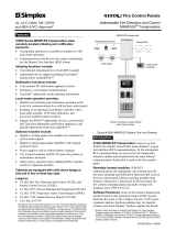
Screen Name or Units
Diagnostic
Alert
Numeric
Data
Alive Indicator
Transmit Data
Receive Data
Receive Data Error
LCD Screen:
Buttons:
+
–
(Up)
Select
(Right)
Next
(Down)
Select
(Left)
Back
D. To Enter the CT (Current Transducer) output voltage and input current ranges:
1. Navigate to the (Set Current Transducer) Setup screen
(see section A above).
2. Press to go to the screen. Use or to select the voltage
mode Current Transducer output voltage (default is ).
3. Press to go to the screen and through the digits. Use or to
select the CT size in amps (default is ).
4. Press to accept the value and go back to the screen.
RS-485 COMMUNICATIONS (S4100-K & S4100-S) DISPLAY SCREEN DIAGRAM
Page 9
Page 13
Page 10
Page 14 Page 15
Page 11 Page 12
PK-A3130-10-00-0APage 16
0.37 to 0.44 ft-l
(0.5 to 0.6 N-m)
The solid state pulse outputs are rated for 30 Vac/dc nom.
Over-Current Protective Device* (not supplied)
Power Source**
3 to 30 Vdc
6 to 30 Vac
Power Source**
3 to 30 Vdc
6 to 30 Vac
Maximum load current is 100 mA at 25 °C. Derate 0.56 mA per °C above 25 °C (e.g. 86 mA@50 °C).
* The over-current protective device must be rated for the short circuit current at the connection point.
** All pulse outputs and communication circuits are only intended to be connected to non-hazardous
circuits (SELV or Class 2). Do not connect to hazardous voltages.
~
=
≤ 100 mA
~
=
≤ 100 mA
Alarm
Energy Output
+ – S
LOAD
LOAD
FCC PART 15 INFORMATION
NOTE: This equipment has been tested by the manufacturer and found to comply with the limits for a class
B digital device, pursuant to part 15 of the FCC Rules. These limits are designed to provide reasonable
protection against harmful interference when the equipment is operated in a residential environment.
This equipment generates, uses, and can radiate radio frequency energy and, if not installed and used in
accordance with the instruction manual, may cause harmful interference to radio communications. This
device complies with part 15 of the FCC Rules. Operation is subject to the following two conditions:
(1) This device may not cause harmful interference, and
(2) this device must accept any interference received, including interference that may cause undesired
operation.
Modifications to this product without the express authorization of the manufacturer nullify this statement.
Additional Resources:
For a copy of the full installation guide for this product, visit www.leviton.com.
CHINA RoHS COMPLIANCE INFORMATION (EFUP Table)
䜘Ԧ〠
ӗ૱ѝᴹ∂ᴹᇣ⢙䍘ᡆݳ㍐Ⲵ〠৺ਜ਼䟿6XEVWDQFHV
䫵3E ⊎+J 䭹&G ޝԧ䬜&U9, ཊⓤ㚄㤟3%% ཊⓤҼ㤟䟊3%'(
⭥ᆀ㓯䐟ᶯ ; 2 2 2 2 2
2 㺘⽪䈕ᴹ∂ᴹᇣ⢙䍘൘䈕䜘Ԧᡰᴹ൷䍘ᶀᯉѝⲴਜ਼䟿൷൘6-7ḷ߶㿴ᇊⲴ䲀䟿㾱≲ԕл
; 㺘⽪䈕ᴹ∂ᴹᇣ⢙䍘㠣ቁ൘䈕䜘ԦⲴḀа൷䍘ᶀᯉѝⲴਜ਼䟿䎵ࠪ6-7ḷ߶㿴ᇊⲴ䲀䟿㾱≲
Z000057-0A
B. To Enter Modbus communication parameters:
1. Navigate to the (set communications) Setup screen
(see section A).
2. Press to go to the screen and through the address digits.
Use or to select the Modbus address (default is ).
3. Press to accept the value and go to the screen. Use or to
select the baud rate (default is ).
4. Press to go to the screen. Use or to select the parity
(default is ).
5. Press to go back to the screen.
E. To Enter the service type to be monitored:
1. Navigate to the (Set System) Setup screen (see section).
2. Press to go to the screen. Use or to select the
configuration (see wiring diagrams - default is ).
3. Press to go back to the screen.
For technical support, contact Leviton at 800-959-6004, or via email at
[email protected]C. To Enter BACnet communication parameters (S4100-S models only):
1. Navigate to the (set BACnet) Setup screen (see section A).
2. Press to go to the screen and through the address digits. Use or
to select the BACnet MAC address (default is ).
3. Press to accept the value and go to the screen. Use or to
select the baud rate (default is ).
4. Press to go to the screen and through the upper four digits of the Device
Instance. Use or to select the ID digits (default is a pseudo-random number).
5. Press to accept the value and go to the screen and through the lower
three digits of the Device Instance. Use or to select the ID digits (default
is a pseudo-random number).
6. Press to accept the value and go back to the screen.
PULSE CONTACT INPUTS (S4100-S
The S4100-S has one pulse input. This input is isolated from the measured circuits. On
models with BACnet communication (S4100-S), they are referenced to the communication
signal ground and the comm output shield terminal. Use with contacts that do not require
current to remove oxidation.
SComm
Output
+
~10 kΩ
Comm
Ground
4-10 VDC
nominal
Equivalent
Circuit
Pulse Input
Contacts
S4100-S
The Comm Shield terminal
is connected to the pulse
input common on BACnet
models only (S4100-S)
A. To Navigate to the Setup screens:
1. Press or repeatedly until screen appears.
2. Press to get to the screen.
3. Press to move through the digits. Use the or buttons to enter your
password (the default is ).
4. Press to move to the first Setup screen ( ) on S4100-K, ( )
on S4100-S.
5. Use or to select the parameter screen you want to set.
6. After you set the parameters you want, use or to select the next Setup
screen or to exit the Setup screens (return to ).
INITIAL SETUP INSTRUCTIONS
TRADEMARK DISCLAIMER: Use herein of third party trademarks, service marks, trade names, brand
names and/or product names are for informational purposes only, are/may be the trademarks of their
respective owners; such use is not meant to imply affiliation, sponsorship, or endorsement.