Page is loading ...

574-xxx
Rev. 4
Fire
Australian
Installation
Manual
4100ES-S1 Fire Indicator Panel
Installation & Maintenance
Australian
Installation &
Maintenance
Manual
LT0394
Issue 1.5


iii
Copyrights and Trademarks
2006, 2012 Tyco Australia Pty Limited. All Rights Reserved.
All specifications and other information shown were current as of document revision date,
and are subject to change without notice.
Tyco, Simplex, the Simplex logo, MAPNET II, IDNet, TrueAlarm, SmartSync,
WALKTEST, MINIPLEX, and TrueAlert are trademarks of Tyco International Services
AG or its affiliates in the U.S. and/or other countries. VESDA is a trademark of Xtralis.
Simplex fire alarm technology is protected by the following U.S. Patent Numbers:
TrueAlarm analog smoke detection: 5,155,468; 5,173,683 and 5,543,777. IDNet and
MAPNET II addressable communications; 4,796,025. TrueAlert addressable notification;
6,313,744 and 6,426,697. SmartSync horn/strobe control; 6,281,789.
Australian Standard AS 4428.1
ActivFire Listing Number afp1682
The 4100ES-S1 is a Fire Indicator Panel manufactured by Tyco Fire Protection Products
for:
Tyco Services Fire & Safety
47 Gilby Road
Notting Hill
VIC 3168
AUSTRALIA
Phone : (03) 9538-7220
Fax : (03) 9538-7255
Name
Serial #
Manufacture Date
Approvals
Manufacture
Product / Site

iv
Non-Disclosure Agreement
Tyco (THE COMPANY) and the User of this/these document(s) desire to share
proprietary technical information concerning electronic systems.
For this reason the company is disclosing to the User information in the form of this/these
document(s). In as much as the company considers this information to be proprietary and
desires that it be maintained in confidence, it is hereby agreed by the User that such
information shall be maintained in confidence by the User for a period of TEN YEARS
after the issue date and only be used for the purpose for which it was supplied.
During this period, the User shall not divulge such information to any third party without
the prior written consent of the company and shall take reasonable efforts to prevent any
unauthorised disclosure by its employees. However, the User shall not be required to
keep such information in confidence if it was in their possession prior to its receipt from
the company; if it is or becomes public knowledge without the fault of the User; or the
information becomes available on an unrestricted basis from a third party having a legal
right to disclose such information.
The User's receipt and retention of this information constitutes acceptance of these terms.
This information is copyright and shall not be reproduced in any form whatsoever.
The 4100ES-S1 Fire Indicator Panel provides a configuration programming facility,
which may be accessed via a programming computer using a “dongle”. Because this
programming facility allows the user to define in detail the operation of the 4100ES-S1
System being customised, changes may be made by the user that prevent this installation
from meeting statutory requirements.
The Company, therefore cannot accept any responsibility as to the suitability of the
functions generated by the user using this programming facility.
End User Liability Disclaimer

v
Model Number & Firmware Revision
This manual applies to product with the following:
Model number : 4100ES-S1
Firmware revision : 1.02.04 and on
Document Name : LT0394 4100ES-S1 Installation & Maintenance Manual
Issue : V1.5 14 June 2012
5 July 2006 Issue 1.0 Original based on LT0350 1.0.7
6 October 2006 Issue 1.1 References to LT0432 and 1976-181 Wiring Diagrams
added.
30 Nov. 2006 Issue 1.2 Updated drawings 1976-181 Sheets 102, 203, 500.
23 Jan. 2007 Issue 1.3 Changes to T-GEN connection, checking system wiring.
21 Feb. 2007 Issue 1.4 Changes to AIU/PPU Brigade Interface mounting
14 June 2012 Issue 1.5 Changes for 4100ES introduction
Document
Amendment Log

vi
Cautions, Warnings, and Regulatory Information
READ AND SAVE THESE INSTRUCTIONS. Follow the instructions in this
installation manual. These instructions must be followed to avoid damage to this product
and associated equipment. Product operation and reliability depends upon proper
installation.
DO NOT INSTALL ANY SIMPLEX
®
PRODUCT THAT APPEARS DAMAGED.
Upon unpacking your Simplex product, inspect the contents of the carton for shipping
damage. If damage is apparent, immediately file a claim with the carrier and notify your
Simplex product supplier.
SAFETY HAZARD - The 4100ES-S1 CPU Card includes a lithium battery. There is
danger of explosion if the battery is incorrectly replaced. Replace only with the same
or equivalent type recommended by the manufacturer. Dispose of used batteries according
to the manufacturer‟s instructions.
ELECTRICAL HAZARD - Disconnect electrical field power when making any internal
adjustments or repairs. All repairs should be performed by a representative or authorized
agent of your local Simplex product supplier.
STATIC HAZARD - Static electricity can damage components. Therefore, handle as
follows:
Ground yourself before opening or installing components (use a suitable wrist-strap
and cable clipped to the frame or an earth connection of the 4100ES-S1).
Prior to installation, keep components wrapped in anti-static material at all times.
EYE SAFETY HAZARD - Under certain fibre optic application conditions, the optical
output of this device may exceed eye safety limits. Do not use magnification (such as a
microscope or other focusing equipment) when viewing the output of this device.
RADIO FREQUENCY ENERGY - This equipment generates, uses, and can radiate
radio frequency energy and if not installed and used in accordance with the instruction
manual, may cause interference to radio communications. It has been tested and found to
comply with the limits defined in AS 4428.0-1997 and Amendment 1:2002.
SYSTEM REACCEPTANCE TEST AFTER SOFTWARE CHANGES - To ensure
proper system operation, this product must be tested in accordance with AS 1670 after
any programming operation or change in site-specific software. Reacceptance testing is
required after any change, addition or deletion of system components, or after any
modification, repair or adjustment to system hardware or wiring.
IMPORTANT: Verify 4100ES Programmer, Executive, and Slave Software
compatibility when installing or replacing system components. Refer to the relevant
Product Bulletins from Simplex Fire Products Australia (www.simplexfire.com.au) for
compatibility information.

vii
Table of Contents
Copyrights and Trademarks ........................................................................................... iii
Approvals ........................................................................................................................ iii
Manufacture .................................................................................................................... iii
Product / Site .................................................................................................................. iii
Non-Disclosure Agreement ............................................................................................ iv
End User Liability Disclaimer .......................................................................................... iv
Model Number & Firmware Revision ............................................................................... v
Document ........................................................................................................................ v
Amendment Log .............................................................................................................. v
Cautions, Warnings, and Regulatory Information ........................................................... vi
Table of Contents .......................................................................................................... vii
List of Figures ............................................................................................................... xiii
List of Tables ................................................................................................................ xiv
Chapter 1 Introduction to the 4100ES-S1 Fire Alarm System .........1
Introduction .................................................................................................................. 1
In this Chapter ............................................................................................................. 1
Basic Configuration.......................................................................................................... 2
Overview ...................................................................................................................... 2
System Design ............................................................................................................. 2
4100ES-S1 Part Codes ................................................................................................... 3
Overview ...................................................................................................................... 3
Assemblies, Cards & & Modules ................................................................................. 3
Kits ............................................................................................................................... 3
Labels (expansion/spares) ........................................................................................... 4
Looms (expansion/spares) .......................................................................................... 4
4100 Part Codes (Non-4100ES) ...................................................................................... 4
Glossary ........................................................................................................................... 5
Chapter 2 Installing 4100ES-S1 Components ..................................2-1
Introduction .............................................................................................................. 2-1
In this Chapter ......................................................................................................... 2-1
Introduction to 4100ES-S1 Cabinet ............................................................................. 2-2
Overview .................................................................................................................. 2-2
Bays ......................................................................................................................... 2-2
CPU Motherboard .................................................................................................... 2-3
CPU Card................................................................................................................. 2-4
CPU Card LEDs ....................................................................................................... 2-5
Operator Interface .................................................................................................... 2-6
Additional CPU Motherboard Modules ................................................................... 2-6
System Power Supply (SPS) ................................................................................... 2-6
The Power Distribution Interface (PDI) .................................................................... 2-8
Mains Outlet ............................................................................................................. 2-8

viii
Step 1. Mounting Cabinets .......................................................................................... 2-9
Overview .................................................................................................................. 2-9
Step 2. Mounting Card Bays to Cabinets .................................................................... 2-9
Overview .................................................................................................................. 2-9
Step 3. Configuring Cards ........................................................................................... 2-9
Overview .................................................................................................................. 2-9
CPU Motherboard Configuration ............................................................................. 2-9
CPU Daughter Card Configuration ........................................................................ 2-10
SPS Configuration ................................................................................................. 2-10
PDI Configuration .................................................................................................. 2-10
Configuring Other Cards ........................................................................................ 2-10
Step 4. Interconnecting Modules and Bays ............................................................... 2-11
Overview ................................................................................................................ 2-11
Guidelines .............................................................................................................. 2-11
Card Interconnections in the CPU Bay .................................................................. 2-11
Card Interconnections Within Expansion Bay ....................................................... 2-11
Basic Bay-To-Bay Interconnections ...................................................................... 2-11
Connecting to Motherboards ................................................................................. 2-12
Step 5. Installing Modules into Expansion Bays ........................................................ 2-13
Overview ................................................................................................................ 2-13
Placement Guidelines ............................................................................................ 2-13
Installing 4” X 5” Cards .......................................................................................... 2-15
Installing Motherboards ......................................................................................... 2-16
Step 6. Installing LED/Switch Modules into Expansion Bays .................................... 2-17
Overview ................................................................................................................ 2-17
The LED/Switch User Interface ............................................................................. 2-18
LED/Switch Controller Card ................................................................................... 2-18
Configuring the LED/Switch Controller Card ......................................................... 2-19
Mounting LED/Switch Modules to the Expansion Bay .......................................... 2-19
Mounting the Additional LED/ Switch Controller Card ........................................... 2-20
LED/Switch Modules .............................................................................................. 2-21
Wiring Instructions ................................................................................................. 2-21
4100ES Fan Control Module ..................................................................................... 2-22
Overview ................................................................................................................ 2-22
Labelling................................................................................................................. 2-22
Mounting & Connection ......................................................................................... 2-22
Programming ......................................................................................................... 2-22
Installing Other Modules ............................................................................................ 2-24
Chapter 3 Networking ........................................................................3-1
Introduction .............................................................................................................. 3-1
In this Chapter ......................................................................................................... 3-1
Network Configuration ................................................................................................. 3-2
Overview .................................................................................................................. 3-2
Ring and Star Configurations................................................................................... 3-2
Connecting Loops .................................................................................................... 3-3
System Design ......................................................................................................... 3-3
Getting Started ............................................................................................................. 3-4
Overview .................................................................................................................. 3-4
Introduction to the 4100 Network Interface Card (NIC) ............................................... 3-4
Overview .................................................................................................................. 3-4
Network Module Illustrations.................................................................................... 3-5
NIC Card LED Indications ........................................................................................ 3-5

ix
NIC Media Cards ..................................................................................................... 3-6
Requirements and Limitations ................................................................................. 3-7
Step 1. Configuring Network Cards ............................................................................. 3-7
Overview .................................................................................................................. 3-7
CPU Motherboard Jumper Settings ........................................................................ 3-7
NIC Card Address Setting ...................................................................................... 3-7
NIC Card Jumper Settings ...................................................................................... 3-8
Wired Media Card Jumper Settings ........................................................................ 3-8
Step 2. Mounting Media Cards to the NIC ................................................................... 3-9
Overview .................................................................................................................. 3-9
Media Card Mounting .............................................................................................. 3-9
Step 3. Mounting Network Cards in the 4100ES-S1 ................................................... 3-9
Step 4. Wiring Network Cards ................................................................................... 3-10
Overview ................................................................................................................ 3-10
Wiring Guidelines ................................................................................................... 3-10
Wiring Distances .................................................................................................... 3-11
Fibre-Optic Wiring .................................................................................................. 3-12
Fibre Optic Connection Types ............................................................................... 3-12
4190-9010 Coupler Requirements ........................................................................ 3-13
Wiring with the Wired Media Card ......................................................................... 3-14
Loop Wiring, mixed Fibre and Cable ..................................................................... 3-16
Chapter 4 The System Power Supply & Alarm Relay Card .............4-1
Introduction .............................................................................................................. 4-1
In this Chapter ......................................................................................................... 4-1
SPS Specifications ...................................................................................................... 4-2
Input/Output/BatterySpecifications .......................................................................... 4-2
SPS Current Consumption ...................................................................................... 4-3
SPS Adjustments ......................................................................................................... 4-4
Adjusting Voltages ................................................................................................... 4-4
Setting Jumpers and DIP Switches ......................................................................... 4-4
SPS LED Indications ................................................................................................... 4-5
Status LEDs ............................................................................................................. 4-5
Troubleshooting an SPS .............................................................................................. 4-6
Overview .................................................................................................................. 4-6
“IDNet Power Monitor Trouble” ............................................................................... 4-6
“Extra Device” .......................................................................................................... 4-6
“Class A Trouble” ..................................................................................................... 4-6
“Earth Fault Search” ................................................................................................ 4-6
“Short Circuit” ........................................................................................................... 4-6
“Channel Fail” .......................................................................................................... 4-6
“No Answer/ Bad Answer” ....................................................................................... 4-6
“Output Abnormal” ................................................................................................... 4-6
The Alarm Relay Card ................................................................................................. 4-7
Overview .................................................................................................................. 4-7
Mounting (factory installed)...................................................................................... 4-7
Configuration ........................................................................................................... 4-8
Notes ........................................................................................................................ 4-8
Warning .................................................................................................................... 4-8
Specification ............................................................................................................ 4-8
Brigade Interfaces ........................................................................................................ 4-9
Overview .................................................................................................................. 4-9
Format ...................................................................................................................... 4-9

x
Applications.............................................................................................................. 4-9
Kit Contents ............................................................................................................. 4-9
Door Mounting ......................................................................................................... 4-9
General Wiring ....................................................................................................... 4-10
Brigade Interfaces, Continued ................................................................................... 4-10
AIU/PPU Mounting ................................................................................................. 4-10
AIU/PPU Wiring ..................................................................................................... 4-10
ASE Mounting ........................................................................................................ 4-10
ASE Wiring............................................................................................................. 4-10
Chapter 5 SPS Field Wiring (4100ES-S1) ..........................................5-1
Introduction .............................................................................................................. 5-1
In this Chapter ......................................................................................................... 5-1
General Field Wiring Guidelines .................................................................................. 5-2
General Guidelines .................................................................................................. 5-2
SPS NAC Field Wiring Guidelines ............................................................................... 5-3
Overview .................................................................................................................. 5-3
Guidelines ................................................................................................................ 5-3
Allocations................................................................................................................ 5-3
Class A (loop) NAC Wiring ...................................................................................... 5-4
Class B (string) NAC Wiring .................................................................................... 5-5
Power Supply Wiring Distances .................................................................................. 5-6
Overview .................................................................................................................. 5-6
Class A NAC Wiring Table ...................................................................................... 5-6
Class B NAC Wiring Table ...................................................................................... 5-7
Using T-GEN 50 with 4100ES-S1 ............................................................................... 5-8
Overview .................................................................................................................. 5-8
Powering the T-GEN 50 .......................................................................................... 5-8
Controlling a T-GEN 50 with a Relay Module ....................................................... 5-10
T-GEN 50 Setting for Relay Operation .................................................................. 5-11
Controlling a T-GEN 50 from a NAC Output .......................................................... 5-12
T-GEN 50 Settings for NAC Operation .................................................................. 5-13
Fitting an Evacuation Control................................................................................. 5-14
Fitting a PA Microphone ........................................................................................ 5-14
100V Speaker Wiring ............................................................................................. 5-15
SPS Auxiliary Power Wiring ...................................................................................... 5-16
Overview ................................................................................................................ 5-16
Guidelines .............................................................................................................. 5-16
Wiring ..................................................................................................................... 5-17
SPS Relay Wiring ...................................................................................................... 5-18
Overview ................................................................................................................ 5-18
Aux 1 Relay............................................................................................................ 5-18
Alarm Relay Card .................................................................................................. 5-18
SPS IDNet Wiring ...................................................................................................... 5-19
Overview ................................................................................................................ 5-19
IDNet Wiring........................................................................................................... 5-19
Guidelines .............................................................................................................. 5-19
Notes ...................................................................................................................... 5-20
Class A (loop) Wiring ............................................................................................. 5-21
Class B (string) Wiring ........................................................................................... 5-22
Chapter 6 PC Software Connections ................................................6-1
Introduction .............................................................................................................. 6-1

xi
In this Chapter ......................................................................................................... 6-1
Software Modes ........................................................................................................... 6-2
Overview .................................................................................................................. 6-2
Software Modes ....................................................................................................... 6-2
Software Modes (continued) .................................................................................... 6-3
Ethernet Service Port and Serial Service Port ............................................................ 6-4
Ethernet Service Port Overview (0566-719 only) ................................................... 6-4
Serial Service Port Overview ................................................................................... 6-4
Chapter 7 Installation Checklist, Commissioning &
Maintenance .............................................................7-1
Introduction .............................................................................................................. 7-1
In this Chapter ......................................................................................................... 7-1
Alignment & Adjustment .............................................................................................. 7-2
Overview .................................................................................................................. 7-2
Power Up & Placing into Operation ............................................................................. 7-3
Maintenance ................................................................................................................ 7-4
Appendix A Card Address DIP Switch ..............................................A-1
Overview .................................................................................................................. A-1
Appendix B Programming Requirements ........................................B-1
Introduction .............................................................................................................. B-1
Required Features ................................................................................................... B-1
Notes ........................................................................................................................ B-1
Appendix C Checking System Wiring ...............................................C-1
Overview .................................................................................................................. C-1
Using the Volt/ Ohm Meter ..................................................................................... C-1
Meter Readings ....................................................................................................... C-2
Appendix D Earth Fault Detection .....................................................D-1
Overview .................................................................................................................. D-1
General Guidelines ...................................................................................................... D-2
Earth Fault Searching from the Front Panel ................................................................ D-3
Overview .................................................................................................................. D-3
Access Level Selection ............................................................................................ D-3
Starting the Earth Fault Search ............................................................................... D-3
Search Option A: Select Location ............................................................................ D-4
Search Option B: Select Channel ........................................................................... D-5
Search Option C: Last Search Result ..................................................................... D-5
Completing the Search ............................................................................................ D-5
Search Results ............................................................................................................ D-6
Overview .................................................................................................................. D-6
Non-Point Faults ...................................................................................................... D-6
Point Faults .............................................................................................................. D-6
Fault Not Found ....................................................................................................... D-7

xii
No Fault ................................................................................................................... D-7
Result Not Available ................................................................................................ D-7
Appendix E Related Documentation .................................................E-1
Appendix F Compatible Actuating Devices .....................................F-1
Introduction .............................................................................................................. F-1
In this Chapter ......................................................................................................... F-1
List of Approved Devices ............................................................................................. F-1
Compatible Detectors, IDNET ..................................................................................... F-4
Compatible Addressable Field Devices, IDNet ........................................................... F-5
Appendix G 4100ES-S1 Specifications .............................................G-1
General .................................................................................................................... G-1
Fuses ....................................................................................................................... G-1
Firmware Features ................................................................................................... G-1
Voltage & Current Ratings of Modules & Assemblies ................................................. G-2
Appendix H Power Supply & Battery Capacity Calculations .........H-1
Power Supply ........................................................................................................... H-1
Battery Capacity ...................................................................................................... H-1
Appendix I List of Drawings ..............................................................I-1

xiii
List of Figures
Figure 1-1. Basic 4100ES-S1 System ............................................................................. 1-2
Figure 2-1. CPU Motherboard (566-227) ....................................................................... 2-3
Figure 2-2. CPU Card (566-719) .................................................................................... 2-4
Figure 2-3. Operator Interface ........................................................................................ 2-6
Figure 2-4. System Power Supply .................................................................................. 2-7
Figure 2-5. The Power Distribution Interface (PDI) ......................................................... 2-8
Figure 2-6. Power and Communication Wiring for Motherboards (note that there
are limitations of where motherboards can be placed – see next section) ............ 2-12
Figure 2-7. Expansion Bay 4”x 5” Card Placement ...................................................... 2-13
Figure 2-8. Expansion Bay Motherboard Placement ................................................... 2-14
Figure 2-9. Slave Card/PDI Connection ........................................................................ 2-15
Figure 2-10. Installing the Motherboard in a 4100ES-S1 Expansion Bay ..................... 2-16
Figure 2-11. LED/Switch Modules ................................................................................. 2-18
Figure 2-12. LED/Switch Controller ............................................................................... 2-18
Figure 2-13. LED/Switch Card Mounting ....................................................................... 2-19
Figure 2-14. Controller Card Mounting .......................................................................... 2-20
Figure 2-15. LED/Switch Controller Wiring (approximately as viewed on the rear
of the open bay door) ............................................................................................. 2-21
Figure 2-16. ME0456 Fan Control Module .................................................................... 2-23
Figure 3-1. Ring/Star Configuration Example ................................................................. 3-2
Figure 3-2. Interconnected Loop Configuration .............................................................. 3-3
Figure 3-3. 4100-6014 Network Interface Card ............................................................... 3-5
Figure 3-4. The 4100-6057 Fiber-Optic Media Card ....................................................... 3-6
Figure 3-5. The 4100-6056 Wired Media Card................................................................ 3-6
Figure 3-6. Media Card Mounting .................................................................................... 3-9
Figure 3-7. Coupler Wiring ............................................................................................ 3-14
Figure 3-8. Wired Media Interconnection between CPU Motherboards in different
panels ..................................................................................................................... 3-15
Figure 3-9. Example of Ring/Loop NetworkWiring ........................................................ 3-16
Figure 4-1. The Alarm Relay Card................................................................................... 4-7
Figure 5-1. The Ferrite Bead ........................................................................................... 5-2
Figure 5-2. Class A (loop) NAC Wiring ............................................................................ 5-4
Figure 5-3. Class B (string) Wiring .................................................................................. 5-5
Figure 5-4. Taking Ancillary Power from NAC1 ............................................................... 5-9
Figure 5-5. Relay Module Connection to a T-GEN 50 .................................................. 5-10
Figure 5-6. NAC Connection to a T-GEN 50 ................................................................. 5-12
Figure 5-7. Wiring an Evacuation Controller to a T-GEN 50 ......................................... 5-14
Figure 5-8. Examples of Evacuation Controls and PA Microphone .............................. 5-15
Figure 5-9. Auxiliary Power Wiring ................................................................................ 5-17
Figure 5-10. Cable Distance & Device Limits for Common Cable Sizes....................... 5-20
Figure 5-11. Class A (loop) Wiring ................................................................................ 5-21
Figure 5-12. Class B (string) Wiring .............................................................................. 5-22
Figure 6-1. Service and Diagnostic Interface .................................................................. 6-2
Figure 6-2. Data Transfer Interface ................................................................................. 6-2
Figure 6-3. Bootloader Interface ...................................................................................... 6-3
Figure 6-4. CPU card ports ............................................................................................. 6-4
Figure 6-5. Front Panel Ethernet Service Port ................................................................ 6-4
Figure A-1. DIP Switch SWx ............................................................................................ A-1

xiv
List of Tables
Table 2-1 Master Controller LEDs 1 through 4 ............................................. 2-5
Table 2-2 Switch/LED Format ..................................................................... 2-22
Table 2-3 Switch Status .............................................................................. 2-22
Table 2-4 Module Installation Documents for 4100ES-S1 .......................... 2-24
Table 3-1 4100 NIC & Media Cards – Electrical and Environmental
Specifications ................................................................................ 3-7
Table 3-2 Wiring Distances ......................................................................... 3-11
Table 3-3 Dual Fiber Optic Cable Communications Distance Examples ... 3-13
Table 3-4 Single Fiber Optic Cable Communications Distance
Examples using 4190-9010 Bi-Directional Couplers .................. 3-13
Table 3-5 566-227 CPU Motherboard Wired Media Connections .............. 3-14
Table 4-1 SPS Input and Output Specifications ........................................... 4-2
Table 4-2 SPS Current Specifications .......................................................... 4-3
Table 4-3 Alarm Relay Card Jumper Positions ............................................. 4-8
Table 5-1 Class A Wiring Distances ............................................................. 5-6
Table 5-2 Class B Wiring Distances ............................................................. 5-7
Table A-1 Card Addresses ............................................................................A-2
Table C-1 Acceptable Zone and Signal Circuit Meter Readings .................. C-2

1-1
The 4100ES-S1 is a compact version of the 4100ES fire alarm, which is intended for use
in applications requiring only one or two loops of addressable devices.
This chapter is an overview of basic system concepts.
Refer to the page number listed in this table for information on a specific topic.
Topic
See Page #
Basic Configuration
1-2
4100ES-S1 Part Codes
1-3
4100 Part Codes (Non-4100ES)
1-4
Glossary
1-5
Chapter 1
Introduction to the 4100ES-S1 Fire Alarm System
Introduction
In this Chapter

1-2
Basic Configuration
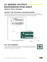
The basic version of the 4100ES-S1 is used for smaller or single-building applications. It
is ideally placed in a small building that requires a limited number of notification
appliances and initiating devices.
If a small building is being expanded, or if other buildings are being constructed in the
same general area (as in a campus application), the basic 4100ES-S1 can be expanded via
networking into one of the larger systems described in Chapter 3.
The basic 4100ES-S1 is a single cabinet containing these items: CPU, System Power
Supply, and optional slave cards.
As standard, the 4100ES-S1 has one IDNet addressable loop that can support up to 250
devices. A second IDNet addressable loop can be added by fitting a 4100-3101AU IDNet
module to the expansion bay in the cabinet (see Chapter 6).
The basic 4100ES-S1 can be expanded with a limited number of 4100-type legacy
card/modules or newer 4” x 5” 4100ES modules.
All appliances and devices are connected to this one cabinet, as shown in Figure 1-1.
ALARM
FIRE
PULL
DOWN
Addressable
station
I/O Module
Supervised IAM
Smoke sensor
with base
Remote line
powered isolator
To additional IDNET devices, up to 250 total
4100
FIRE ALARM CONTROL
PULL TO OPEN
DOOR
EMERGENCY
OPERATING
INSTRUCTI
ONS
ALARM OR TROUBLE
CONDITION:
- SYSTEM INDICATOR
FLASHING, TONE ON.
TO
ACKNOWLE
DGE:
- PRESS "ACK" LOCATED
UNDER FLASHING
INDICAT
OR.
- REPEAT OPERATION UNTIL
ALL REPORTS ARE
ACKNOWLE
DGED.
TO SILENCE
ALARM SIGNALS:
- PRESS "ALARM
SILENCE".
TO RESTORE SYSTEM
TO NORMAL:
- PRESS
"SYSTEM
RESET."
- PRESS "ACK" TO
SILENCE TONE DEVICE.
OPERATO
R
INTERFAC
E
PANEL
FIR
E
ALA
RM
SYST
EM
TROU
BLE
SIGN
ALS
SILEN
CED
POW
ER
O
N
PRIORIT
Y 2
ALA
RM
SYST
EM
SUPERVI
SORY
SYSTEM IS NORMAL
12:35:15 am MON 29 JAN
96
ACKNO
WLEDG
E
TB
L
AC
K
ACK
SUP
V
ACK
ALAR
M
ALA
RM
ACK
SILEN
CE
ALAR
M
RES
ET
SYST
EM
SI
M
PL
EX
TI
M
E
RE
C.
C
O.
21
90-
91
55
.09
A
21
90-
91
57
.01
2A
IN
ST
AL
.
IN
ST
RU
C.
57
5-
59
2
21
90-
91
61
.04
A
21
90-
91
63
.04
A
IN
ST
AL
..I
NS
TR
UC
.
57
5-
27
9
33
33
BA
UD
RA
TE
28
VD
C
51
9-
57
6
A
1
2
3
4
5
6
7
8
AD
DR
ES
S
CO
DE
1
2
3
4
5
6
7
8
A
D
D
R
E
S
S
C
O
D
E
51
9-
63
8
1 2 3 4 5 6
7 8
O
N
Thermal sensor
with base
to Device
Figure 1-1. Basic 4100ES-S1 System
Overview
System Design

1-3
4100ES-S1 Part Codes
This section lists the parts that are supported by the 4100ES-S1 Fire Alarm System.
The following is a list of assemblies, cards and modules used in 4100ES-S1:
These parts are included in the base 4100ES-S1:
742-516 CPU Motherboard (566-227)
4100-7158 CPU Card (566-719)
4100-9848AU System Power Supply, Australian version
4100-6033 Alarm Relay Card (566-058) plugged onto the SPS and used
to supply the Brigade I/F relays.
PA0915 Fuse Distribution Board, connected to the Auxiliary Power
terminals of the System Power Supply
4100-2300 Expansion Bay Assembly (includes the metalwork with the
PDI back-plane)
4100-1288 64 LED/64 Switch Controller module with mounting plate
4100-1282 8 SW/16 LED red/yellow module (2 off)
These parts may be used to expand a 4100ES-S1:
4100-1282 8 SW/16 LED red/yellow module
4100-3101AU IDNET Module – 250 point capacity
4100-3107AU IDNet+ Module – 246 point capacity, four loops
4100-3204 4 Point Relay Module
4100-3206 8 Point Relay Module
4100-1289 64 LED/64 Switch Controller module
4100-1287 24 Switch/24 red LED module
4100-1284 8 Switch 16 red/green LED module
4100-1281 8 Switch 8 yellow LED module
4100-0160 Internet Interface Module (566-355).
ME0456 Fan Control Module
The following kits are available to install in a base 4100ES-S1:
Brigade Interfaces
FP0935 ASE Door Kit (ASE not included)
FP0937 PPU/AIU Door Kit (PPU/AIU not included)
Other
4100-KT0448 Fused DC Distribution Bd, XSPS AU Mounting
4100-KT0468 4100 Motherboard to 4100U Bay, Mounting Kit
4100-0766K T-GEN 50 and 4100U Mounting Bracket Kit
ME0460 T-GEN 50 Evacuation Control Switch and Label
ME0490 T-GEN 50/4100U Dynamic Microphone and lead
Continued on next page
Overview
Assemblies, Cards &
& Modules
Kits

1-4
4100ES-S1 Part Code, Continued
LB0602 Operator I/F ISO/Test Card
LB0605 Fan Control Zone Insert Card
526-873 Slide In Label, LED Switch Module, 1 Sheet of 6
4100-1294 LED Module Slide In Labels, Panel Set
LM0309 4100U Mains Lead With Filter
LM0310 4100U Battery Lead Set, 18U-21U
734-008 Harness, Power Comms, 4 Way, 2ft Length
734-075 Harness, Power Comms, 4 Way, 8ft Length
116-226 Sw/LED Module Ribbon Cable, 26 Way, 2in
116-227 Sw/LED Module Ribbon Cable, 26 Way, 6in
The following is a list of existing 4100+/A/U cards and modules that may be used with
4100ES-S1.
4100-5004 8 AZF Monitor Zone
4100-0113 Dual RS232 Modem Interface
4100-3003 8 Relay Module
4100-4321 6 Supervised Relays
4100-3024 24 Relay Module
4100-0302 24 I/O Module
4100-0111 Quad Isolator Module
4100-6078 Modular Network Card (requires 2 media cards)
4100-6056 Wired Media Card RS485
4100-6057 Fibre Optic Media Card
4100-0154 VESDA High Level Interface
Labels
(expansion/spares)
Looms
(expansion/spares)
4100 Part Codes (Non-4100ES)

1-5
Glossary
AZF Alarm Zone Facility – means of grouping multiple detectors or devices,
and providing common indication and control.
Class A Wiring Method of connecting multiple devices or units in a loop. This requires
up to twice as much wire but means that a short or open circuit in any
one section will not prevent communication with every device.
Class B Wiring Connection of multiple devices sequentially, or with spurs, uses the
minimum amount of cable, but a single wiring fault can affect all
devices at once.
FIP Fire Indicator Panel – usually abbreviated to “panel”.
GPO General Power Outlet – mains power socket.
IDNet Individual Device Network – latest generation of Simplex analogue
addressable devices and the 2-wire loop that connects them.
MAPNet Multi-Application Peripheral Network – an earlier version of
addressable device communication superseded by IDNet. Some
MAPNet devices can be used on IDNet loops.
NAC Notification Appliance Circuit – switched DC output, usually with
supervision for powering notification appliances and warning system
devices.
NIC Network Interface Card – provides network communications between
multiple 4100/4100ES panels.
PDI Power Distribution Interface – the backplane power distribution system
used in 4100ES.
PID Product Identification (part number).
RUI Remote Unit Interface – 2-wire communications loop used to connect
4100/4100ES master panels with slave transponders.
SPS System Power Supply – the main 4100ES power supply and battery
charger module. Also includes an IDNet loop port, three NAC outputs,
and the brigade relay card.

1-6
/