Page is loading ...

Features
IDNet expansion module for 4100ES fire alarm
control panels:
Provides 250 IDNet device point control including
both QuickConnect and QuickConnect2 sensors
Extends the 4100ES QuickConnect and
QuickConnect2 sensor sensitivity to seven levels of
adjustment from 0.2% to 3.7%
Requires a single block (4” x 5”) module location
Also compatible with 4100U systems
Intended for upgrade of Simplex
®
4010 fire alarm
control panels:
Allows for system expansion beyond 250 addressable
points, up to the 2500 point capacity of the 4100ES
control panel
Systems can retain the installed QuickConnect and/or
QuickConnect2 sensors
Additional IDNet SLC (Signaling Line Circuit)
channels are available from 4100ES standard or
expansion IDNet modules
UL Listed to Standard 864
Description
4010 System Upgrade. The Simplex model 4010 fire
alarm control panel provides for up to 250 addressable
points using IDNet communications. One of the 4010
unique devices is the QuickConnect sensor.
QuickConnect sensors provide TrueAlarm analog
sensing in a feature optimized package, primarily suited to
smaller systems. The original QuickConnect sensor has been
replaced with the QuickConnect2 sensor.
When a facility expands beyond the capacity of the
4010 control panel, the preferred upgrade is the 4100ES fire
alarm control panel. Standard 4100ES IDNet signaling line
circuits (SLCs) are not compatible with QuickConnect
sensors. However, with the 4100-3106, all of the 4100ES
compatible IDNet devices and the QuickConnect and
QuickConnect2 sensors can be connected to the same fire
alarm control panel.
Expanded Sensitivity Range. Additionally, the 4100ES
with the 4100-3106 module can provide a full range of
sensitivity for the QuickConnect sensors with seven levels
of adjustment from 0.2% to 3.7%. Standard sensitivities are
1.5%, 2.0%, 2.5%, and 3.7%. Sensitivities of 0.2%, 0.5%,
and 1% are for special applications in clean areas. (For
detailed application information including sensitivity
selection, refer to Installation Instructions 574-709.)
* This product has been approved by the California State Fire Marshal (CSFM) pursuant to
Section 13144.1 of the California Health and Safety Code. See CSFM Listing 7165-0026:251
for allowable values and/or conditions concerning material presented in this document. It is
subject to re-examination, revision, and possible cancellation. This product was not approved
by MEA (NYC) as of document revision date. Additional listings may be applicable, contact
your local Simplex product supplier for the latest status. Listings and approvals under
Simplex Time Recorder Co. are the property of Tyco Fire Protection Products.
ALARMFIRE
PULL DOWN
SIM PLEX TI M E RECO RDER CO.
4090-9002
RELAY IAM
INSTAL. INSTR. 574-184
DATE CODE:
1
5
6
7
8
1
2
3
4
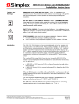
Addressable station
Monitor ZAMs
and Relay IAMs
Supervised IAM
QuickConnect
TrueAlarm sensor
Modular TrueAlarm
sensor with base
Modular TrueAlarm sensor
with IDNet isolator base
To additional IDNet
devices, up to 250 total
POWER
BEFORE
SERVICING
CAUTION
DISCONNECT
4009 IDNet NAC EXTENDER
TM
4009 IDNet NAC
Extender
New 2500 point 4100ES
Fire Alarm Control Panel
QuickConnect2
TrueAlarm sensor
Original Facility
Requirements
Facility Expansion
Requirements
Original 250 point
4010 Fire Alarm
Control Panel
To additional IDNet
devices, up to 250
total per IDNet SLC
4100-3106 IDNet module
with QuickConnect
Sensor Support
IDNet SLC
channel for
standard devices
4010 System Expansion using a 4100-3106 IDNet Module
4100-3106 Specifications
Capacity 250 points
Standby
Current
with 250 devices 275 mA
without devices 75 mA
per device 0.8 mA
Alarm
Current
with 250 devices 265 mA
without devices 115 mA
per device 1 mA
Operating Temperature
Range
32 F to 120 F (0 C to 49 C)
Humidity Range
Up to 93% RH, non-condensing
@ 90° F (32° C)
Mounting
Single 4100ES block; 4” x 5”
(102 mm x 127 mm)
Installation Instructions 574-800
Fire Control Panels
UL, ULC, CSFM Listed; 4100-3106 IDNet Expansion Module with
FM Approved* QuickConnect/QuickConnect2 Sensor Compatibility
S4100-0039-4 2/2014

Addressable Device Control Reference
Overview. The 4100ES provides standard addressable
device communications for IDNet compatible devices and
accepts optional modules for communications with
MAPNET II compatible devices. Using a two-wire
communications circuit, individual devices such as
manual fire alarm stations, TrueAlarm sensors,
conventional IDC zones, and sprinkler waterflow
switches can be interfaced to the addressable controller to
communicate their identity and status.
Addressability allows the location and condition of the
connected device to be displayed on the operator interface
LCD and on remote system annunciators. Additionally,
control circuits (fans, dampers, etc.) may be individually
controlled by using a relay IAM (individual addressable
module).
Addressable Operation. Each addressable device on
the communication channel is continuously interrogated
for status condition such as: normal, off-normal, alarm,
supervisory, or trouble. Sophisticated poll and response
communication techniques ensure supervision integrity
and allow for "T-tapping" of the circuit for Class B
(Style 4) operation. The device LED blinks to indicate
receipt of a communications poll and is steady on to
indicate an alarm (or trouble) condition.
IDNet Channel Capacity. The CPU bay system power
supply (SPS) provides an IDNet signaling line circuit
(SLC) that supports up to 250 addressable monitor and
control points intermixed on the same pair of wires.
Additional IDNet circuit modules are available for 64,
127, or 250 addressable devices.
Wiring Requirements for IDNet Communications.
Refer to the specifications chart below. Distances are for
shielded or unshielded wire. Shielded wire may provide
protection from unexpected sources of interference.
Wiring Specifications
Size 18 AWG minimum (0.82 mm
2
)
Type
Preferred Shielded twisted pair (STP)
Acceptable* Unshielded twisted pair (UTP)
Farthest Distance from
Control Panel to Device
Up to 2500 feet (762 m)
Total Wire Length Allowed
With “T” Taps for Class B
Wiring
Up to 10,000 ft (3 km).
* Some applications may require shielded wiring. Review system
with your local Simplex product supplier.
Additional Simplex Product Reference
Product Data Sheet Reference
QuickConnect2 Sensors S4098-0034
Standard TrueAlarm Sensors S4098-0019
Basic 4100ES Fire Alarm Control
Panels
S4100-0031
Basic 4100ES Fire Alarm Control
Panels with EPS/EPS+ for
IDNAC Addressable Notification
S4100-0100
Tyco Fire Protection Products • Westminster, MA • 01441-0001 • USA S4100-0039-4 2/2014
www.simplex-fire.com
© 2014 Tyco Fire Protection Products. All rights reserved. All specifications and other information shown were current as of document revision date and are subject to change without notice.
TYCO, SIMPLEX, and the product names listed in this material are marks and/or registered marks. Unauthorized use is strictly prohibited.
Slot 1 Slot 8Slot 7Slot 6Slot 5Slot 4Slot 3Slot 2
Expansion Bay Chassis
Block A
Block B
Block C
Block D
Block E
Block F
Block G
Block H
Size Definitions: Block = 4” W x 5” H card area
Slot = 2” W x 8” H motherboard with daughter card
Expansion Bay Module Loading Reference
/