MULTIPLEX 21 4237 Building Instructions
- Category
- Remote controlled toys
- Type
- Building Instructions
This manual is also suitable for
Page is loading ...

2
D
F
GB
I
E
Sicherheitshinweise
Prüfen Sie vor jedem Start den festen Sitz des Motors und der Luftschraube - insbesondere nach dem Transport, härteren Landungen
sowieAbstürzen. Prüfen Sie ebenfalls vor jedem Start den festen Sitz und die richtige Position der Tragflächen auf dem Rumpf.
Akku erst einstecken, wenn Ihr Sender eingeschaltet ist und Sie sicher sind, daß das Bedienelement für die Motorsteuerung auf "AUS"
steht.
Im startbereiten Zustand nicht in den Bereich der Luftschraube greifen.
Vorsicht in der Luftschraubendrehebene - auch Zuschauer zur Seite bitten!
Zwischen den Flügen die Motortemperatur durch vorsichtige Fingerprobe prüfen und
vor einem Neustart den Motor ausreichend abkühlen lassen. Die Temperatur ist richtig, wenn Sie den Motor problemlos berühren
können. Insbesondere bei hohen Außentemperaturen kann dieses bis zu 15 Minuten dauern.
Denken Sie immer daran: Niemals auf Personen und Tiere zufliegen.
Conseils de sécurité
Avant chaque décollage, vérifiez la fixation du moteur et de l'hélice, notamment après le transport, après les atterrissages violents et
après un “Crash”. Vérifiez également, avant chaque décollage la fixation ainsi que le positionnement de l’aile par rapport au fuselage.
Ne branchez l’accu de propulsion que si vous êtes sûr que votre émetteur est allumé et que l’élément de commande moteur est en
position “ARRET”.
Ne mettez pas vos doigts dans l’hélice! Attention à la mise en marche, demandez également aux spectateurs de reculer.
Entre deux vols, vérifiez en posant un doigt dessus, la température du moteur, laissezle refroidir suffisamment avant le prochain
décollage. La température est correcte si vous pouvez maintenir votre doigt ou votre main sur le moteur. Le temps de refroidissement
peut varier jusqu’à 15 minutes s’il fait particulièrement chaud.
Pensez-y toujours: ne volez jamais vers ou au-dessus des personnes ou des animaux.
Safety notes
Before every flight check that the motor and propeller are in place and secure - especially after transporting the model, and after hard
landings and crashes. Check also that the wing is correctly located and firmly secured on the fuselage before each flight.
Don’t plug in the battery until you have switched on the transmitter, and you are sure that the motor control on the transmitter is set to
“OFF”.
When the model is switched on, ready to fly, take care not to touch the propeller. Keep well clear of the propeller disc too, and ask
spectators to stay back.
Allow the motor to cool down after each flight. You can check this by carefully touching the motor case with your finger. The
temperature is correct when you can hold your finger on the case without any problem. On hot days this may take up to 15 minutes.
Please keep in mind at all times: don’t fly towards people or animals.
Note di sicurezza
Prima di ogni decollo controllare che il motore e la eliche siano fissati stabilmente - specialmente dopo il trasporto, atterraggi duri e se il
modello è precipitato. Controllare prima del decollo anche il fissaggio e la posizione corretta delle ali sulla fusoliera.
Collegare la batteria solo quando la radio è inserita ed il comando del motore è sicuramente in posizione ”SPENTO”.
Prima del decollo non avvicinarsi al campo di rotazione della eliche. Attenzione alla eliche in movimento - pregare che eventuali spettatori
si portino alla dovuta distanza di sicurezza!
Tra un volo e l’altro controllare cautamente con le dita la temperatura del motore e farli raffreddare sufficientemente prima di ogni nuovo
decollo. La temperatura è giusta se si possono toccare senza problemi. Specialmente con una temperatura esterna alta questo può
durare fino a 15 minuti.
Fare attenzione: Non volare mai nella direzione di persone ed animali.
Advertencias de seguridad
Compruebe antes de cada despegue que el motor y la hélice estén fuertemente sujetados, sobretodo después de haberlo transportado,
de aterrizajes más fuertes así como después de una caída. Compruebe igualmente antes de cada despegue que las alas estén bien
sujetas y bien colocadas en el fuselaje.
Conectar la batería, cuando la emisora esté encendida y Usted esté seguro que el elemento de mando para el motor esté en ”OFF”.
No meter la mano en la zona inmediata a la hélice cuando el avión esté a punto de despegar. ¡Cuidado con la zona de la hélice! ¡Pedir a
los espectadores que se aparten!
Entre los vuelos hay que comprobar cuidadosamente la temperatura del motor con el dedo y dejar que el motor se enfríe antes de volver
a despegar. La temperatura es correcta, si puede tocar el motor sin problemas. Sobretodo en el caso de temperaturas del ambiente muy
altas, esto puede tardar unos 15 minutos.
Recuerde: No volar nunca hacía personas o animales.

15
# 21 4237
Examine your kit carefully!
MULTIPLEX model kits are subject to constant quality checks throughout the production process, and we sincerely hope that you are
completely satisfied with the contents of your kit. However, we would ask you to check all the parts before you start construction,
referring to the Parts List, as we cannot exchange components which you have already modified. If you find any part is not
acceptable for any reason, we will readily correct or exchange it once we have examined the faulty component. Just send the
offending part to our Model Department. Please be sure to include the purchase receipt and the enclosed complaint form, duly
completed.
We are constantly working on improving our models, and for this reason we must reserve the right to change the kit contents in
terms of shape or dimensions of parts, technology, materials and fittings, without prior notification. Please understand that we
cannot entertain claims against us if the kit contents do not agree in every respect with the instructions and the illustrations.
Caution!
Radio-controlled models, and especially model aircraft, are by no means playthings in the usual sense of the term. Building and
operating them safely requires a certain level of technical competence and manual skill, together with discipline and a
responsible attitude at the flying field. Errors and carelessness in building and flying the model can result in serious personal
injury and damage to property. Since we, as manufacturers, have no control over the construction, maintenance and operation
of our products, we are obliged to take this opportunity to point out these hazards and to emphasise your personal responsibility.
Additional items required for the “Merlin”:
MULTIPLEX receiving system components for the Merlin
RX-6-SYNTH IPD receiver 35 MHz A+B band Order No. 5 5876
alternatively: 40 / 41 MHz band Order No. 5 5877
or RX-7-DR light M-Link receiver 2.4 GHz Order No. 5 5810
Nano S servo 4 x required (2 x ailerons, elevator, rudder) Order No. 6 5120
Battery charger:
MULTIcharger LN-3008 EQU Order No. 9 2540
for LiPo, LiIo and LiFe batteries (2S / 3S) and NiMH
and NiCd batteries (four to eight cells)
Merlin Tuning power set: Order No. 33 2653
Contents:
Himax 2212-1180 motor, BL-20 S-BEC speed controller, 7 x 4” and 8 x 5” folding
propellers, taper collet, driver and 33 mm Ø spinner
Merlin Tuning power set, Li-Batt powered: Order No. 33 3653
Contents:
As above, plus 1 x Li-Batt BX 3/1-450 (M6)
Flight battery: Li-Batt BX 3/1-450 (M6) Order No. 15 7104
Receiver battery for glider version 4AAA / Micro cells, W-format Not in MPX range
Tools:
Pliers, side-cutters, screwdriver, scissors, balsa knife.
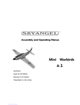
Note: please remove the illustration pages from the centre of the instructions.
Specification:
Wingspan: 783 mm
Overall length: 598 mm
All-up weight, glider, min. approx.: 265 g
All-up weight, electric, min. approx.: 325 g
Total surface area: 11.3 dm²
Wing loading, min.: 23 g/dm² glider, 29 g/dm² electric
RC functions: Aileron, elevator, rudder, motor
GB

16
Like any other aircraft, this model has static limits! Steep dives and silly, imprudent manoeuvres may cause structural failure
and the loss of the model. Please note: damage caused by incompetent flying is obvious to us, and we are not prepared to
replace components damaged in this way. It is always best to fly gently at first, and to work gradually towards the model’s
limits. The aircraft is designed to cope with our ‘Tuning’ (upgrade) power system, but is only capable of withstanding the flight
loads if it is built exactly as specified, and is in perfect structural order (i.e. not damaged). Further upgrade measures are
possible, but should only be attempted if you have plenty of experience in this field, as additional structural reinforcements will
be required.
Important note
This model is not made of styrofoam™, and it is not possible to glue the material using white glue, polyurethane or epoxy;
these adhesives only produce a superficial bond which gives way when stressed. For most joints use medium-viscosity
cyano-acrylate glue, preferably our Zacki-ELAPOR®, # 59 2727 - the cyano glue optimised specifically for ELAPOR®
particle foam. At some points the extremely low-viscosity (thin) type, Zacki ELAPOR super liquid, # 59 2728, is required.
If you use Zacki-ELAPOR® you will find that you do not need cyano ‘kicker’ or activator for most joints. However, if you wish
to use a different adhesive, and are therefore obliged to use kicker / activator spray, we recommend that you apply the
material in the open air as it can be injurious to health.
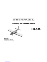
1. Before assembling the model
Please check the contents of your kit before you start working on
it.
You will find Figs. 1 + 2 and the Parts List helpful here.
Please do not throw away the EPS packaging carrier (speckled
white), as it is the ideal support for transporting the finished
model, and is required for use with the transport bag, # 76
3316. If you want to fit the completed electric version of the
model in the packaging carrier, always fix the propeller with a
rubber band, otherwise it may be damaged.
2. Preparation
2.1 Preliminary assembly of the servo assemblies “AQR”,
“AQL”, “AS” and “AH”,
Fig. 3
Cut down the servo output arms (with 1 mm Ø linkage holes) to
the shapes shown in Fig. 3, then fit the output arms on the servos
as shown in the drawing, after setting the servos to neutral from
the transmitter - don’t forget to centre the trims! The aileron
pushrods are later connected to the second hole from centre
(lever length approx. 10 mm) of the servo output arms.
The rudder and elevator pushrods are later connected to the first
hole from centre (lever length approx. 8 mm) of the servo output
arms.
Clip the rudder and elevator servos into the servo frames 44.
We have assigned capital letters to these preliminary steps: the
aileron servo assemblies are termed “AQ”-“R”ight and “L”eft;
the rudder servo assembly is termed “AS”, and that for the
elevator“AH”.
Before installing the servos please check that the servo output
arms do not foul any part of the model. You may need to trim
away a little foam around the output arms, or cut back the arms
themselves, to provide proper clearance.
2.2 Preliminary assembly of the control surface horn
assemblies “RA”, Fig. 4
Fit the socket-head grubscrews 24 in the three twin pushrod
connector barrels 23. The swivel barrels are then pushed into
the control surface horns 22 until they snap into place.
2.3 Preliminary assembly of the elevator crank mechanism
“HM”, Fig. 5
Mount the swivel pushrod connector 25 on the elevator crank 54
using the nut 27 and the washer 26, taking care to fit the parts
the right way round. Lightly tighten the nut with your fingers (the
pushrod connector must be free to rotate), then apply a drop of
glue to the outside of the nut to prevent it working loose. Fit the
socket-head grubscrew 24 in the pushrod connector, then place
the prepared crank 54 in the bearing housing 50. Close the
housing by fitting the cover 51 using the screws 30. Check that
the system works smoothly, and make any adjustments required.
2.4 Preliminary assembly of the two fuselage nose-cones:
“Glider” and “Power-glider”.
2.4.1 Glider: preliminary assembly of the glider nose-cone unit
“S”, Fig. 6
Fix the fuselage nose-cone 43 to the fuselage nose fairing /
motor bulkhead 42 using the two screws 37.
2.4.2 Power-glider: preliminary assembly of the power unit
“AE”, Figs. 7 + 8
This description covers the optional power set, # 33 2653 (this
set is the perfect match for the Merlin, as everything harmonises
correctly. The power unit is supplied with two different propellers:
with the smaller prop the motor operates at optimum efficiency,
thereby providing maximum flying times. With the larger prop the
motor is operating close to its performance limit, and with a
good flight battery (e.g.# 15 7104) the model then has vertical
climb capability):
Screw the motor to the fuselage fairing / motor bulkhead 42
using the four screws supplied with the power set. Fit the propeller
driver as shown in the drawing. Ensure that there is 1 mm
clearance between the motor bulkhead and the propeller driver
when the parts are in place; check that the driver does not foul
the screw-heads.
3. Completing the fuselage
3.1 Completing the “outside” of the right-hand fuselage shell,
Fig. 9
Lay the right-hand fuselage shell 4 “flat” on your working surface
(table). Cut the fuselage longeron 69 to a length of 510 mm, and
glue it in the external channel in the fuselage shell, taking care to
secure it along its full length. Use a cloth to wipe off excess
adhesive immediately.
Caution: it is essential that the fuselage shells lie flat (straight)
on the bench surface when the longerons are fitted, as you
will not be able to correct any error subsequently! This is the
stage at which you produce either a straight or a bent fuselage.
Don’t blame the foam parts if the fuselage ends up crooked!
Cut the aerial sleeve 67 to a length of 320 mm and glue it in the
fuselage shell. Note: install the sleeve even if you are installing
a 2.4 GHz system, as it stiffens the fuselage!
Page is loading ...
Page is loading ...
Page is loading ...
Page is loading ...
Page is loading ...
Page is loading ...
Page is loading ...

24
3.2 Completing the “inside” of the right-hand fuselage shell,
Fig. 10
Turn the fuselage shell over, cut the longeron 70 to a length of
276 mm and glue it in place. Now glue the wing retainer plate 49
and the fuselage hatch frame 40 in the right-hand fuselage side,
and align everything very carefully.
Ensure in particular that the wing retainer plate is correctly
positioned, otherwise it will not be possible to insert the wing
panels later. The best method of checking the position of the
wing retainer plate before gluing it to the fuselage shell is to
slide the right-hand wing panel into place temporarily.
The prepared elevator servo assembly AH can now be glued in
place: apply the adhesive to the long side of the servo frame 44
only. Deploy the servo lead towards the nose, and temporarily
secure it with adhesive tape. Finally glue the prepared elevator
mechanism HM to the fuselage shell.
3.3 Installing the elevator pushrod, Fig. 11 (see also Fig. 22)
Cut down the snake inner sleeve 63 to a length of 170 mm, and
the outer sleeve 65 to 140 mm. Slip the inner and outer sleeves
over the steel elevator pushrod 61. Set the servo output arm to
neutral from the transmitter, and connect the pre-formed end of
the steel pushrod to the innermost hole (lever length approx. 8
mm) of the servo output arm, working from the outside. Slip the
opposite end of the steel pushrod through the swivel pushrod
connector 25 mounted on the elevator mechanism HM, and
temporarily tighten the grubscrew 24 at the neutral position. The
outer sleeve can now be glued permanently in the channel in the
fuselage.
3.4 Completing the “outside” of the left-hand fuselage shell,
Fig. 12
Lay the left-hand fuselage shell 3 “flat” on your working surface
(table). Cut the fuselage longeron 68 to a length of 470 mm, and
glue it carefully in the fuselage shell, following the same procedure
as described in Step 3.1.
3.5 Joining the fuselage shells, Fig. 13
Offer up the two fuselage shells “dry” (no glue), and check that
they fit together neatly; it is a good idea to insert the left-hand
wing panel to check alignment. When you are confident that
everything fits snugly, glue the two fuselage shells together.
You will undoubtedly have noticed that the elevator servo is now
“locked in”. Normally you will never again need access to the
servo, but if it should develop a fault you can “get at it” by cutting
open the fuselage at the point marked XX. Once you have replaced
the servo, the new “hatch” can be fixed in place again with a few
drops of cyano.
Apply glue to the joint surfaces, place the fuselage shells
together and align them accurately, working smoothly and
rapidly. Check that the fuselage is straight (i.e. neither bent
nor twisted). Insert the tailplane and the wing panels to check
alignment. If necessary, you will find that the position of the
fuselage shells can be adjusted slightly for a brief period after
joining, as the cyano adhesive takes a few minutes to cure
completely.
Glue the twin rudder horn (RA) 22 in place after completing this
stage.
3.6 Installing the rudder linkage, Fig. 14 (see also Fig. 25)
Glue the prepared rudder servo assembly AS in the fuselage,
applying the adhesive to the long sides of the servo frame 44
only. Deploy the servo lead towards the receiver compartment,
and temporarily tape it in place.
Cut the snake inner sleeve 64 to a length of 230 mm, and the
outer sleeve 66 to 180 mm. Slip the inner and outer sleeves over
the steel pushrod 62. Set the servo output arm to neutral from
the transmitter, and connect the pre-formed pushrod end (Z-
bend) to the innermost hole (lever length approx. 8 mm) of the
servo output arm, working from the outside. Slip the opposite
end of the steel pushrod through the swivel barrel 23 of the
rudder horn SA, and tighten the grubscrew 24 to fix it at the
neutral position. The outer sleeve can now be glued in the channel
in the fuselage.
3.7 Completing the glider / power-glider versions
3.7.1 Completing the glider version, Fig. 15
Glue the prepared glider nose-cone S to the fuselage.
3.7.2 Completing the power-glider version, Figs. 16 + 17
Glue the prepared power assembly AE to the fuselage as shown,
then temporarily install the speed controller, as described in
Step 7.2, and carry out a test-run (take care!) to check the direction
of rotation of the motor (anti-clockwise as seen from the front). If
the motor shaft spins in the wrong direction, swap over any two
of the three wires between the motor and the controller.
The propeller blades can now be fitted, as shown in Fig. 17.
4. Completing the tailplane, Fig. 18
Glue the left-hand tailplane panel 7 to the “tailplane joiner with
shaft” 52, and glue the right-hand tailplane panel 8 to the
“tailplane joiner with retainer” 53.
Temporarily install the tailplane in the fuselage by pushing both
panels in to the point where they engage together. To remove the
tailplane, press on the point marked X to unlatch the retainer.
5. Completing the wings
5.1 Installing the wing spars and wing retainers, Fig. 19
Remove rough edges from the wing spars 60 and check that
they are a snug fit in the wing panels. When you are satisfied
with the fit, glue the spars in the wings together with the wing
retainers 47 + 48. These joints must be strong, so take care at
this point! Glue the two twin horns 23 in the recesses in the
ailerons.
5.2 Installing the wing-mounted servos, Fig. 20
Cut the slots in the wing recesses to accept the servo mounting
lugs, and remove a little extra foam to accommodate the servo
lead. Push the prepared servo assemblies AQR and AQL into
the wing from the underside to the point where they lie flush with
the top surface of the wing; apply a drop of cyano to the servo
mounting lugs to fix them in place. Connect the two aileron
pushrods 29 to the holes in the servo output arms located 10
mm from the shaft centre, working from outside to inside, then
install the two prepared pushrods by connecting them to the
pushrod barrel connectors 23 and the twin aileron horns 22.
Check once again from the transmitter that the servos are at
neutral, then tighten the socket-head grubscrews 24 to clamp
the pushrods.
5.3 Releasing the ailerons, Fig. 21
The ailerons are released by cutting a slot 1 mm wide at both
ends using a sharp balsa knife; these points are marked with
an X.
Check that the ailerons move freely in both directions, then
temporarily fix the servo fairings 45 + 46 to complete the wings.
6. Joining the wings and fuselage, Fig. 22
Run the aileron servo leads through the wing retainer plate and
into the fuselage, so that they dangle out of the opening in the
underside. The wing panels can now be inserted into the
fuselage; ensure that the spars slide into the wing retainers on
each side. Push the wing panels together so that the projecting
tongues 47/48 engage inside the Wing retainer plate 49.To
remove the wings it is necessary to press the tongues down
gently with one finger until the panels can be withdrawn.
7 Installing the RC components, checking the working systems
7.1 Glider version, Fig. 23

25
Install the remaining RC system components in the model in
the arrangement shown in the illustration. Note that the position
of these items determines the Centre of Gravity. Use the Velcro
(hook-and-loop) tape 20 + 21 to secure the parts.
7.2 Power-glider version, Fig. 24
Install the remaining RC system components in the model as
shown in the illustration, using the Velcro tape 20 + 21. For the
power-glider the receiver has to be installed further aft in the
fuselage; check that the cables are long enough to allow the
plugs and sockets to be connected outside the fuselage. The
speed controller can be secured in the space under the canopy.
7.3 Control surface settings (guide only!) and initial test-run
Control surface travels (measured at the widest point of the
control surface):
Ailerons: 12 / 6 mm +/-
Elevator: 6 / 6 mm +/-
Rudder: 12 / 12 mm +/-
Flaps: < 4 mm down
Spoilers: 7 mm up
Elevator trim compensation:
Spoilers 1 mm “down”
Flaps < 1 mm +/-
Motor < 1 mm “down”
Centre of Gravity: approx. 40 mm aft of
the wing root leading edge
Longitudinal dihedral: 1 - 1.5°
(This setting is correct when the socket-head grubscrew is visible
through the hole in the side of the fuselage.)
Motor downthrust (fixed): approx. 10° down, sidethrust: 0°
Ensure that all the receiving system components are correctly
installed and connected. Check the control surface settings, and
the direction of rotation of all the servos. Ensure that none of the
electrical leads can foul or get tangled in the motor when it is
rotating (glue or tape them in place!). Check the direction of
motor rotation once again (injury hazard!).
The tailplane is at the correct neutral position when you can see
the socket-head grubscrew through the hole in the side of the
fuselage, as shown in Fig. 27. Before you tighten the grubscrew,
remember to check from the transmitter that the elevator servo
is exactly at neutral (centre)!
7.4 Replacing the elevator servo
Normally the servo will never need to be replaced, but if it should
develop a fault, cut along the narrow channel as shown in Fig.
22, and remove the “hatch” thus formed. Replace the servo, then
stick the hatch back in place with a few drops of cyano. If you use
a really sharp knife and work neatly, the repair will be virtually
invisible.
8. Rudder servo cover, Fig. 25
The rudder servo recess can now be sealed by applying the
sticker 6*. This is accomplished by cutting a piece of the decal
sheet backing paper (30 x 40 mm, rounded corners) and placing
it centrally over the appropriate sticker from the decal sheet. This
“hatch cover” can now be applied over the servo well. Please
ensure that the adhesive cannot possibly stick the servo output
arm, and prevent it moving!
9. Aileron servo fairings, Fig. 26
The aileron servo fairings 45 + 46 can now be stuck permanently
to the wing. Glue the two servo covers 36 to the top surface of the
wing panels.
10. Centre of Gravity position, Fig. 27
The CG can be corrected by adjusting the position of the flight
battery, and by adding a little additional ballast if required. The
CG must be located exactly 40 mm aft of the wing root leading
edge (i.e. exactly coincident with the servo lead channel).
11. Preparations for the first flight
Please wait for a day with as little breeze as possible for the
model’s initial test-flight. The evenings hours are often ideal for
calm conditions. If this is your first radio-controlled model
aeroplane, look for an experienced model flyer who is prepared
to help you, as it is very difficult to master the skills all by yourself.
Locate the nearest model flying club or clubs and ask them for
suitable contacts. Your local model shop should be able to
furnish you with addresses of clubs. Our flight simulator for the
PC is a very useful aid for those first steps in model flying; the
simulator can be downloaded from our website www.multiplex-
rc.de at no charge. A suitable interface lead for MPX transmitters
(Order No. # 8 5153) can be obtained from your model shop.
12. Be sure to carry out a range check before the first flight!
Just before the flight, charge up the transmitter battery and the
flight pack using the recommended procedures. Ensure that
“your” channel is not already in use before you switch the
transmitter on. Ask your assistant to walk away from the model,
holding the transmitter. The transmitter aerial should be fitted
but completely collapsed. Your assistant should operate one of
the functions constantly while you watch the servos. The non-
controlled servos should stay motionless up to a range of about
60 m, while the controlled one should follow the stick movements
smoothly and without any delay. Please note that this check can
only give reliable results if the radio band is clear of interference,
and if no other radio control transmitters are in use - even on
different channels. If the initial range check is successful, repeat
it with the motor running at “half-throttle”. There should be no
more than a very slight reduction in effective radio range with the
motor turning. If you are not sure about anything, please don’t
risk a flight. Send the whole system (including battery, switch
harness and servos) to the Service Department of your RC
system manufacturer and ask them to check it.
13. Important points prior to the first flight
Glider
A test-glide can provide a useful pointer to the model’s trim: hold
it at shoulder-height and push it forward firmly into any breeze. If
the model veers to one side, apply opposite rudder trim to correct
it. If one wing hangs down, you need to correct the aileron trim.
Flying at the slope
Ridge soaring is an extremely attractive form of model flying.
Flying for hours on end in slope lift, without needing any outside
aid for launching, must be one of the finest of modelling
experiences. But to fly out over the valley, search for a thermal,
“milk” the lift to the limits of vision (take care: the model is small!),
bring it down again in a continuous series of aerobatic
manoeuvres, and then to repeat the whole show - that must
surely be the last word in model flying.
But take care - there are dangers for your model lurking at the
slope. Firstly, in most cases landing is much more difficult than
at a flat field site. It is usually necessary to land in the lee of the
hill where the air is turbulent; this calls for concentration and a
confident, high-speed approach. A landing on the slope face, i.e.
right in the slope lift, is even more difficult. Here the trick is to
approach slightly downwind, up the slope, and flare at exactly
the right moment, just before touch-down.
Electric flight
The electric-powered version gives you the maximum measure
of independence: from a flat field you can reach a sensible height

26
(around 50 to 100 m) about ten times from a single battery charge,
whilst at the slope you can use the motor to get you “back home”
if the dreaded downdraft appears (downdraft: the opposite of a
thermal, forcing you to land down in the valley when the lift fails).
Aerobatics
With the recommended power system the Merlin flies in a very
similar manner to a hot-line electric model: it has vertical climb
capability, and can carry out any aerobatic manoeuvre you can
name. As such it makes a thoroughly enjoyable model even for
the experienced flyer. It’s a great model to keep with you at all
times.
14. Safety
Safety is the First Commandment when flying any model aircraft.
Third party insurance is a basic essential. If you join a model
club suitable cover will usually be available through the
organisation. It is your personal responsibility to ensure that
your insurance is adequate (powered model aircraft). Make it
your job to keep your models and your radio control system in
perfect order at all times. Check the correct charging procedure
for the batteries you are using. Make use of all sensible safety
systems and precautions which are advised for your system. An
excellent source of practical accessories is the MULTIPLEX main
catalogue, as our products are designed and manufactured
exclusively by practising modellers for other practising modellers.
Always fly with a responsible attitude. You may think that flying
low over other people’s heads is proof of your piloting skill; others
know better. The real expert does not need to prove himself in
such childish ways. Let other pilots know that this is what you
think too. Always fly in such a way that you do not endanger
yourself or others. Bear in mind that even the best RC system in
the world is subject to outside interference. No matter how many
years of accident-free flying you have under your belt, you have
no idea what will happen in the next minute.
All of us in the MULTIPLEX team hope you have many hours of
pleasure building and flying your new model.
MULTIPLEX Modellsport GmbH & Co. KG
Product development and maintenance
Klaus Michler

27
Part No. Description MaterialDimensions
No. off
1 1 KIT building instructions Paper, 80 g/m² A4
2 1 Decal set Printed adhesive film 500 x 175 mm
3 1 L.H. fuselage shell Moulded Elapor foam Ready made
4 1 R.H. fuselage shell, incl. fin Moulded Elapor foam Ready made
5 1 L.H. wing panel Moulded Elapor foam Ready made
6 1 R.H. wing panel Moulded Elapor foam Ready made
7 1 L.H. tailplane panel Moulded Elapor foam Ready made
8 1 R.H. tailplane panel Moulded Elapor foam Ready made
Small items set
20 3 Velcro tape, “mushroom” Plastic 25 x 60 mm
21 3 Velcro tape, “felt” Plastic 25 x 60 mm
22 3 Twin control surface horn Plastic Ready made
23 3 Twin pushrod connector Metal Ready made, 6 mm Ø
24 4 Socket-head grubscrew Metal M3 x 3 mm
25 1 Swivel pushrod connector Metal Ready made, 6 mm Ø
26 1 Washer Metal M2
27 1 Nut Metal M2
28 1 Allen key Metal 1.5 mm A/F
29 2 Pre-formed aileron pushrod (Z-bend) Metal 1 Ø x 50 mm
30 2 Countersunk screw (tailplane housing) Metal M2 x 8 mm
36 2 Wing servo well cover Plastic 35 x 35 mm
37 2 Cheesehead screw, glider nose-cone Metal M2.5 x 8mm
Plastic parts set
40 1 Fuselage hatch frame Inj. moulded plastic Ready made
41 1 Fuselage hatch Inj. moulded plastic Ready made
42 1 Fuselage fairing / motor bulkhead Inj. moulded plastic Ready made
43 1 Glider nose-cone Inj. moulded plastic Ready made
44 2 “Nano” servo frame, upright Inj. moulded plastic Ready made
45 1 L.H. servo fairing Inj. moulded plastic Ready made
46 1 R.H. servo fairing Inj. moulded plastic Ready made
47 1 L.H. wing retainer Inj. moulded plastic Ready made
48 1 R.H. wing retainer Inj. moulded plastic Ready made
49 1 Wing retainer plate Inj. moulded plastic Ready made
50 1 Tailplane bearing housing Inj. moulded plastic Ready made
51 1 Tailplane bearing housing cover Inj. moulded plastic Ready made
52 1 Tailplane joiner with shaft Inj. moulded plastic Ready made
53 1 Tailplane joiner with retainer Inj. moulded plastic Ready made
54 1 Tailplane crank Inj. moulded plastic Ready made
Wire and rod, wing spars
60 2 Wing spar CFRP flat strip 6 x 1.5 x 225 mm
61 1 Steel elevator pushrod, with Z-bend Metal 0.8 Ø x 210mm
62 1 Steel rudder pushrod, with Z-bend Metal 0.8 Ø x 275mm
63 1 Elevator snake inner sleeve Plastic 2 / 1 Ø x 170mm (230mm*)
64 1 Rudder snake inner sleeve Plastic 2 / 1 Ø x 230mm
65 1 Elevator snake outer sleeve Plastic 3 / 2 Ø x 140mm (200mm*)
66 1 Rudder snake outer sleeve Plastic 3 / 2 Ø x 180mm (200mm*)
67 1 Aerial sleeve Plastic 3 / 2 Ø x 320mm
68 1 L.H. fuselage longeron GRP rod 1.3 Ø x 470mm (510mm*)
69 1 R.H. fuselage longeron GRP rod 1.3 Ø x 510mm
70 1 Top fuselage longeron GRP rod 1.3 Ø x 276mm (510mm*)
* Supplied length => cut to length as required.
Page is loading ...
Page is loading ...
-
 1
1
-
 2
2
-
 3
3
-
 4
4
-
 5
5
-
 6
6
-
 7
7
-
 8
8
-
 9
9
-
 10
10
-
 11
11
-
 12
12
-
 13
13
-
 14
14
-
 15
15
-
 16
16
-
 17
17


MULTIPLEX 21 4237 Building Instructions
- Category
- Remote controlled toys
- Type
- Building Instructions
- This manual is also suitable for
Ask a question and I''ll find the answer in the document
Finding information in a document is now easier with AI
Related papers
-
MULTIPLEX Twister Assembly Manual
-
-
-
HiTEC Funcub Owner's manual
-
-
-
-
-
-
Other documents
-
 Aeronaut Premiant II Building Instructions
-
 Aeronaut Xenon RC Building Instructions
-
Merlin CESSNA T-206 User manual
-
aero-naut Joker RC Building Instructions
-
Merlin pilot 500 User manual
-
 skyangel Mini Warbirds A-1 Assembly And Operating Manual
-
-
Ripmax WOT4-E Quick start guide
-
Ripmax mini Bossanova User manual
-
 skyangel HR-100 Assembly And Operating Manual


