Page is loading ...

Xenon
Xenon building instructions
1
Building Instructions
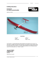
Xenon RC model aircraft
Order No. 1311/00
The “Xenon” is a high-performance electric-powered thermal soarer. Its low all-up weight and
aerodynamically efficient wingtips guarantee superb handling and flying qualities, combined with a
broad speed range and low rate of sink.
Specification
Wingspan approx. 2500 mm
Length approx. 1340 mm
Wing area approx. 53.5 dm²
All-up weight approx. 1.2 - 1.5 kg
Wing loading approx. 22.5 - 28 g / dm²
RC functions: Aileron, elevator
rudder, flaps,
throttle

Xenon
Xenon building instructions
2
Parts List
1.) Fuselage, pigmented white 1 GRP, ready made
2.) Canopy, locating peg and GRP tongue 1 Ready made
3.) Rudder, pigmented white 1 GRP, ready made
4.) Tailplane and elevator, covered 1 Wooden construction, ready made
5.) Wing centre section with flaps, covered 1 Wooden construction, ready made
6.) Outboard wing panels with ailerons, covered 2 (l + r) Wooden construction, ready made
7.) Wing joiner, incorporating dihedral 2 GRP / CFRP, 8 Ø x 115 mm
8.) Wing incidence peg 2 CFRP, 3 Ø x 20 mm
9.) Front wing locating peg 1 Beech, 4 Ø x 38 mm
10.) Wing retainer screw 1 Nylon, M5 x 20 mm
11.) Servo well cover, aileron / flap 2 pairs Vac.-moulded plastic
12.) Motor bulkhead 1 GRP, ready made
13.) Rudder hinge 2 Ready made
14.) Clevis, threaded coupler and pin 6 Ready made
15.) Aileron / flap pushrod 4 Pre-formed wire, 73 mm
16.) Rudder pushrod 1 Pre-formed wire, 50 mm
17.) Elevator pushrod 1 Pre-formed wire, 20 mm
18.) Servo mount 4 pairs Wood, ready made
19.) Short horn (ailerons, rudder) 3 Plastic, ready made
20.) Long horn (elevator, flaps) 3 Plastic, ready made
21.) Rudder / elevator servo well covers 2 GRP, ready made
22.) Self-tapping screw 8 1.9 x 6.5 mm
23.) Tailplane retainer screw 1 Aluminium, M4 x 70 mm
24.) Screw guide 1 Plastic, 5 Ø x 4 Ø x 63 mm
25.) Screw guide support block 1 Balsa, 6 x 10 x 64 mm
26.) Captive nut 1 Ready made, M4
27.) Decal set 1 set Ready made
28.) Building instructions 1 Ready made
Essential items
Building board (e.g. 16 mm hardwood board), balsa knife, metal file, ruler, straight edge, screwdriver,
5-minute epoxy adhesive, thin and thick cyano-acrylate, paper masking tape, soldering iron, 4 m x 0.4
sq mm twisted servo cable, six-pin connector.
Recommended RC equipment
Six servos (all 9 - 13 g types)
Receiver (min. five channels)
Recommended power system
Motor: Actro CL6 (No. 7001/06)
Actro C8 (No. 7002/38)
Speed controller: Actronic 45 BEC (No. 7002/51)
Battery: 3S LiPo / LiIon
Folding propeller: CAMcarbon 13 x 8” (No. 7234/57)

Xenon
Xenon building instructions
3
Wing
The wing consists of three panels: the centre section, which is screwed to the fuselage, and the
two outboard panels, which plug into the centre section. All the wing panels are of traditional built-
up construction and are supplied assembled and film-covered. The ailerons and camber-changing
flaps are already hinged, and the facing ribs at the dihedral breaks are correctly angled.
The centre section is fixed to the fuselage by means of a central screw. Melt the covering film over
the screw-hole using the tip of a hot soldering iron; the heat in the tip will immediately glue the
surrounding film down again. A locating peg has to be glued in the leading edge of the wing; mark
the position of the hole in the fuselage on the leading edge before drilling the hole for the peg.
Open up the servo wells using a small soldering iron.
The aileron and flap servos are installed using the servo mounts supplied. To determine their
exact position, push the mounts onto the servo, and place this assembly in the servo well “dry” (no
glue). Mark the exact position where the mounts are to be installed.
Glue the servo mounts in the wing using thick cyano or 5-minute epoxy. Allow the glue to set hard.
Check that the servo output arms are exactly at right-angles to the hinge pivot axis, then fix the
servos in the mounts using hot-melt adhesive.
Cut off the connector end of the servo leads. For each servo draw a twisted extension cable (not
included in the kit) through the wing panels. You will need to fit three-pin plugs and sockets at the
transition point between the centre section and the outboard wing panels.
Solder the twisted extension cables to the servo leads, and fit a heat-shrink sleeve over each
soldered joint for additional protection. An alternative is to install extension leads terminating in
sockets, and connect the servo plugs to them. In this case you do not need to cut off the servo
leads, but the connectors must be secured with adhesive tape to avoid any danger of them
working loose.
A six-pin plug and socket connection is required at the transition from the wing centre section to
the fuselage. Note that all the positive servo wires can be soldered to a common pin, as can the
negative wires.
Connect the radio control system, and check the operation of the installed servos from the trans-
mitter. At this point you can also check the servo neutral positions, and set the correct directions of
rotation.
Glue the horns in the flaps and ailerons prior to installing the linkages; the horns must line up
accurately with the servo output arms.
The short horns are intended for the ailerons; the linkage hole should be located exactly over the
aileron hinge pivot axis. Glue the longer horns in the flaps, as described for the ailerons.
The linkages themselves are each assembled from a pre-formed wire pushrod, a threaded coupler
and a plastic clevis. Take care to produce sound soldered joints between the threaded couplers
and the rods. Epoxy can be used as an alternative.
Carefully cut out the servo well covers and fix them to the wings using clear adhesive tape, after
checking that the servo output arms do not foul the inside of the well covers when they deflect.
Join the wing panels using the CFRP / GRP joiner rods. Note that the joiners incorporate the cor-
rect dihedral.
Glue the incidence pegs in the outboard panels to prevent them rotating on the joiner rods. Leave
about 10 mm projecting, and sand the exposed ends to a rounded profile.
The outboard panels are held in place by strips of adhesive tape applied to the top surface of the
wing along the separation line.
Tailplane
The tailplane is screwed to the tail end of the fuselage, and can be removed for ease of transport.
Use a soldering iron to remove the covering film over the central hole in the tailplane, then glue
the metal captive nut in the hole from above (!) using 5-minute epoxy. It is a good idea to remove
a little more film all round the hole, to achieve as strong a glued joint as possible.
The top surface of the tailplane is that to which the elevator is attached using an adhesive tape
hinge.

Xenon
Xenon building instructions
4
The next step is to install the screw guide support block and the actual screw guide (plastic tube),
to allow the tailplane to be screwed in place. Glue the tube to the balsa block using 5-minute
epoxy.
Glue this assembly in the fuselage, exactly vertical and exactly below the hole in the tailplane
saddle (fuselage). Now drill a hole in the bottom of the fuselage so that the retaining screw can be
passed through the guide.
The tailplane can now be screwed to the fuselage.
At this point attach the wing to the fuselage, and sight along the fuselage from the nose to check
whether the tailplane is exactly parallel to the wing. If not, carefully file away material from the
tailplane saddle to correct. Take great care here: the model’s flying characteristics depend to a
large extent on correct alignment of the flying surfaces.
The elevator servo should be glued to the servo well cover using 5-minute epoxy: roughen the
GRP surface thoroughly before applying glue, as the production process tends to leave traces of
mould release agent which could cause the glued joint to fail.
Extend the elevator servo lead with twisted cable so that it reaches the area under the wing,
where the receiver will be installed.
Assemble the elevator linkage as described for the ailerons and flaps; the system consists of a
horn, pre-formed wire pushrod, clevis and threaded coupler. Here again it is important that the
linkage hole in the horn is located exactly over the hinge pivot axis.
Finally fix the servo well cover to the fuselage using four self-tapping screws.
Rudder
The rudder is attached to the fin by means of two hinges; the hinge slots are already prepared.
Glue the hinges in place using 5-minute epoxy after applying a tiny drop of oil to the pivot pins to
prevent them becoming jammed.
The rudder servo is glued to the servo well cover using 5-minute epoxy, as described previously
for the elevator; roughen the GRP surface thoroughly before applying glue, as the production
process tends to leave traces of mould release agent which could cause the glued joint to fail.
Extend the rudder servo lead with twisted cable so that it reaches the area under the wing, where
the receiver will be installed.
Assemble the rudder linkage as described for the ailerons and flaps; the system consists of a
horn, pre-formed wire pushrod, clevis and threaded coupler. Once again it is important that the
linkage hole in the horn is located exactly over the hinge pivot axis.
Finally fix the servo well cover to the fuselage using four self-tapping screws.
Fuselage
The canopy is detachable, to ensure that the battery can be swapped easily during a flying ses-
sion.
Glue the GRP tongue to the inside of the canopy in such a way that it engages under the fuse-
lage flange. At the front end it is located by a steel pin glued into the canopy.
Alternatively you may prefer to attach the canopy using adhesive tape or two small self-tapping
screws.
Installing the electric motor
The first step is to glue the GRP motor bulkhead in the fuselage: press it firmly into position, tack it
in place with thin cyano, and then apply a fillet of 5-minute epoxy to secure it. The front face of the
fuselage defines the correct thrustline of the motor: the motor shaft should be inclined down by
about 2°, with a very little sidethrust (approx. 1° to the right, as seen from the tail).
Allow the glue to set hard, then slide the propeller / spinner onto the motor shaft. You may need to
sand back the front face of the fuselage until it matches the diameter of the spinner accurately,
and lines up correctly. Please work slowly and only remove material in small increments - your
reward will be a perfect result.
The motor can now be screwed to the bulkhead, and connected to the speed controller. Check the
motor’s direction of rotation at this point; in fact, it is best to check this before installing the motor.
A small block of wood with a central hole can be pushed onto the shaft to help you see its

Xenon
Xenon building instructions
5
direction of rotation. Don’t use the propeller for this - injury hazard!
Assemble and install the folding propeller, hub and spinner as described in the instructions sup-
plied with the parts.
Fix the speed controller to the fuselage side using a small patch of Velcro (hook-and-loop) tape.
The wires between the speed controller and the motor should also be secured to avoid any
chance of them fouling the rotating parts of the motor. Don’t pack the controller in foam, as this
could cause it to overheat.
The flight battery is secured to the bottom of the fuselage, again using Velcro tape.
Final work
The correct Centre of Gravity (75 mm from the root leading edge) can be set by adjusting the
position of the flight battery. This CG location is a safe value for the first few flights. Later on you
may wish to adjust the CG to suit your personal preference - but by no more than +/- 5 mm.
When you have found the correct flight pack location, secure it with Velcro tape, and mark its
position.
Check the control functions: the rudder should deflect to a maximum of 25 mm either side of
neutral. The correct elevator travels are 10 mm up and 8 mm down. Check, and then check again,
that the control surfaces actually move in the correct direction, i.e. “left stick” really does equate to
the model turning “left”.
The ailerons should deflect 12 mm up and 8 mm down. Remember that for a right turn the right
aileron rises, and the left aileron falls.
Set the flaps to deflect up by 2 mm, and down by as much as possible. This function should be
assigned to a slider on the transmitter, so that you have proportional control of the flaps. You will
find that varying the flap settings gives you very wide control of your model’s performance in the
air.
The “butterfly” or “crow” setting can be programmed to act as a landing aid: both ailerons up as far
as possible, and both flaps down as far as possible. You will need to compensate for the resultant
pitch trim change by applying about 2 mm down-elevator, but the exact value needs to be found
by test-flying. In this configuration the model can approach for landing at a very steep angle
without gaining speed.
The plotted stickers can now be applied to the finished model, using the arrangement shown in the
kit box illustration.
The first flight
Once you have completed all the checks, there is nothing to stop you carrying out the model’s first
flight. If you have little or no experience in model flying, we urgently recommend that you join a
model flying club and ask a proficient model pilot to help you: he will carry out the initial test-flights
for you, and then help you to learn the art of model flying step by step.
It is also possible to learn to fly without outside help: first wait for a day with little or no breeze.
Launch the model with a firm push forward into any wind, keeping the wings and fuselage level.
Allow the aircraft to climb at a shallow angle, initially using the elevator only to adjust the rate of
climb. Don’t let the model slow up too much. If it turns to one side, gently move the rudder in the
opposite direction to return to straight flight.
Once the model is at a safe altitude, switch the motor off and allow it to glide. Use the controls
very gently at first until you feel familiar with the aeroplane’s response to commands. Don’t get
over-confident too quickly, and maintain plenty of height at all times - model flying is a sophis-
ticated skill which needs to be learned - just like driving a car or riding a bike.
Always land the model with its nose pointing directly into wind. Let it glide towards the ground at a
shallow angle, and don’t apply up-elevator until it is just about to touch down. Never carry out any
major corrections with the rudder when the model is close to the ground!
Safety notes, hazard warnings
Model flying is a fascinating hobby. However, we urge you to observe the following basic rules
when flying a model aircraft, as this will avoid annoying and endangering anyone else.
In Germany you are only permitted to fly model aircraft using a 35 MHz or 2.4 GHz radio control
system.
Your model should only be flown at a site where you will not annoy or endanger anyone; it is al-

Xenon
Xenon building instructions
6
ways best to use approved model flying sites.
Never fly towards or over spectators. Keep any high-risk flying manoeuvres well away from other
people.
Never attempt to repair your radio control system; always leave such work to the experts. Any
home modifications to your RC system inevitably invalidate its official approval.
Do not switch your transmitter on until and unless you have ensured that you will not cause inter-
ference to any other radio control systems in the vicinity; typically through a “channel clash” (two
transmitters on the same frequency).
If possible, join a model flying club, where you will find plenty of friendly people to help with all
your queries and problems.
Please note: if damage ensues due to failure to observe these instructions, the guarantee is
rendered invalid. We accept no liability for consequent damage which results from such ac-
tions. Please follow the building instructions to the letter when completing and operating this
model. The building instructions include information on safe flying. This model is in no respect
a children’s toy.
All of us in the aero-naut Modellbau team hope you have many hours of fun with your “Xenon”!
aero-naut Modellbau GmbH & Co KG, Stuttgarter Strasse 18-22, 72766 Reutlingen, www.aero-naut.com
/