Page is loading ...

Function introduction
Important: Read All Instructions Prior to Installation
Product Data
Safety & Warnings
• DO NOT install with power applied to device.
• DO NOT expose the device to moisture.
Quick Start
How to install:
• Step 1: turn on your wall controller.
• Step 2: activate inclusion mode on your Z-Wave controller.
• Step 3: activate inclusion mode of your wall controller by pressing the “inclusion/exclusion” button or long
press “ALL ON/OFF” button over 3 seconds.
Product Description
The Wall controller is a Security Enabled Z-Wave Plus device that can both control other Z-Wave devices and
activate scenes in Gateways. The wall controller can be included and operated in any Z-Wave network with
other Z-Wave certified devices from other manufacturers and/or other applications. All non‐battery operated
nodes within the network will act as repeaters regardless of vendor to increase reliability of the network.
Although it is controlling other devices, the device cannot act as Z-Wave network controller (primary or
secondary), so a security enabled controller is needed for take full advantage of all functionally for the device.
It also supports the Over The Air (OTA) feature for the product’s firmware upgrade.
The wall controller has following functions:
1.Control of groups of other Z-Wave devices using 'ON', 'OFF', Dim and Color Control commands.
2. Activation of scenes in Gateways.
The encryption modes that the wall controller supports are S0, S2 Unauthenticated. When the wall controller is
being included into a Z-Wave network, you can use your primary controller/gateway to enable one encryption
mode or disable encryption. (The primary controller/gateway shall support encryption mode configuration).
09.ZV9002T3US.04765
Z-Wave Frequency
Power Supply
Power Consumption
Operating temperature
Relative humidity
Dimensions
Material
908.42 MHz (US)
100-240VAC, 50/60Hz
< 0.5W
0 to 40°C
8% to 80%
75x120x29.1mm
Tempered glass panel with capacitive touch buttons
Installation Guide
Please read carefully the enclosed user manual before installation of wall controller, in order to ensure an
error-free functioning.
The wall controller unit supplied as complete set for flush mounting in the standard US size wall boxes.
ATTENTION: Only authorized technicians under consideration of the country specific installation
guidelines/norms may do works with 100-240V mains power. Prior to the assembly of the product, the voltage
network has to be switched OFF and ensured against re-switching.
Inclusion (Add the device to a Z-Wave network)
1. Set primary controller/gateway into inclusion mode (Please refer to your primary controllers manual on how
to turn your controller into inclusion).
2. Make sure the wall controller does not belong to any Z-Wave network (please refer to the part “How to check
whether the wall controller included to a network” of this manual).
3. Short press the “inclusion/exclusion” button, or press and hold down “ALL ON/OFF” button for over 3
seconds, the wall controller will be set to inclusion mode, and waiting to be included, then LED indicator turns
on and blinks 6 times quickly to indicate successful inclusion.
Once the wall controller quits “inclusion mode”, the LED indicator will turns off. There are 3 methods for the wall
controller to quit “inclusion mode”:
1. Automatically quits after successful inclusion.
2. Quits after 25 seconds timeout.
3. Press and hold down “ALL ON/OFF” button for over 3 seconds, or short press the “inclusion/exclusion”
button to quit.
Exclusion (Remove the device from a Z-Wave network)
There are two exclusion methods:
Method 1: Exclusion from the primary controller/gateway as follows:
1. Set the primary controller/gateway into exclusion mode (Please refer to your primary controllers manual on
how to set your controller into exclusion).
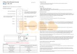
Z-Wave Wall Controller SR-ZV9002T3-CCT-US
Inclusion/Exclusion” Button
Back side
19.4 mm 43.58 mm
65.58 mm
AC Power input
83.00 mm
Front side
L L N N
PRI:
Uin=100- 240 VAC
Iin=15mA MA X
Out=Z-Wav e Sig nal
SR-ZV9002T3
-CCT-US
SW1
Z-Wav e Controller
0% PWM1 + 100% PWM2
ALL ON/OFF button, broadcast to turn on/off all
LED indicator
Decrease whole brightness Increase whole brightness
Save and recall 3 scenes
Color Wheel for adjusting relative
brightness between PWM1 and PWM2
Group 4
100% PWM1 + 0% PWM2
50% PWM1 +50% PWM2
Group 2
Group 3
100% PWM1 + 0% PWM20% PWM1 + 100% PWM2

2. Short press the “inclusion/exclusion” button, or press and hold down “ALL ON/OFF” button for over 3
seconds, the wall controller will be set to exclusion mode, and waiting to be excluded, then LED indicator turns
on and shows 3 short blinks and 1 long blink to indicate successful exclusion.
Once the wall controller quits “exclusion mode”, the LED indicator will turns off. There are 3 methods for the
wall controller to quit “exclusion mode”:
1. Automatically quits after successful exclusion.
2. Quits after 25 seconds timeout.
3. Press and hold down “ALL ON/OFF” button for over 3 seconds, or short press the “inclusion/exclusion”
button to quit.
Method 2: Factory reset the wall controller will force the wall controller to be excluded from a network. (please
refer to the part “Factory Reset” of this manual)
Note: Factory reset is not recommended for exclusion, please use this procedure only if the primary
controller/gateway is missing or otherwise inoperable.
How to check whether the wall controller already included to a network
Operate any button to check if there is indication from the LED indicator, and no LED indication means the wall
controller does not belong to any network.
If the wall controller already belongs to a network, follow the exclusion process before including it in your
network. Otherwise inclusion of this device will fail.
Factory Reset
Press and hold down “inclusion/exclusion” button for over 8 seconds, LED indicator will blink slowly to indicate
successful factory reset, release “inclusion/exclusion” button, the wall controller will restart automatically.
Association
Z-Wave devices control other Z-Wave devices. The relationship between one device controlling another device
is called association. In order to control a different device, the controlling device needs to maintain a list of
devices that will receive controlling commands. These lists are called association groups and they are always
related to certain events (e.g. button pressed). In case the event happens all devices stored in the respective
association group will receive a common wireless command.
Association Groups:
Each group supports maximum 12 nodes for association, the same device can be associated with multiple
groups on the wall controller simultaneously, to ensure better control experience, the wall controller shall
remove the associated devices that are not under working status from association groups in time.
Set and unset associations:
(Note: All association information will be cleared automatically once the wall controller is excluded from a
network.)
Associations can be assigned and remove either via Z-Wave commands or using the device itself.
1. Set association by operating primary controller/gateway to send packets to the wall controller:
The primary controller/gateway sends packets to the wall controller using “Command Class ASSOCIATION” or
“Command Class Multi Channel Association”
2. Set association by operating the wall controller and devices to be controlled:
To control a Z-Wave device from the Wall Controller the node ID of this device needs to be assigned to one of
the four association groups. This is a three-step process:
1. Press and hold down “ALL ON/OFF” button on the wall controller for over 3 seconds, LED indicator turns on.
2. Click any Group number button on the wall controller within 25 seconds to add the device to be controlled to
the association group, double click any Group number button on the wall controller within 25 seconds to
remove the device to be controlled to the association group.
3. Operate the device to be controlled to send Node Information Frame (please refer to the device manual)
within 15 seconds, or set the device to exclusion mode within 15 seconds, since it will send Node Information
Frame in exclusion mode, LED indications are as follows:
LED blinks 5 times to indicate that the wall controller failed to add the associated device (the association group
has already added maximum quantity associated devices that it supports ).
LED blinks 10 times to indicate that the wall controller added the associated device successfully.
LED blinks 8 times to indicate that the wall controller removed the associated device successfully.
To remove all associated devices in an association group on the wall controller directly:
1. Press and hold down “ALL ON/OFF” button on the wall controller for over 3 seconds, LED indicator turns on.
2. Click any Group number button on the wall controller 5 times continuously within 25 seconds to remove all
associated devices of this group, LED indicator blinks 8 times to indicate that the associated devices are
removed successfully.
Group
Identifier Group Name Max Nodes Description
1. Send “Command Class Device Reset Locally” to
associated devices of this group to report factory
reset information when factory reset the wall
controller.
2. Double click a group number of the wall controller
to send command to associated devices of this
group using “Command Class Central Scene”.
1. Press and hold down button "1" to activate group
in order to switch the associated devices with a
Basic Set or dim these devices by using the two
brightness buttons or adjust color temperature by
using color wheel.
2. Short press Scene button S1/S2/S3, direct control
of associated devices using Scene Activation Set,
Scene ID = 0x10 / 0x20 / 0x30.
3. Press and hold down Scene button S1/S2/S3,
direct control of associated devices using Scene
Conf Set, Scene ID = 0x10 / 0x20 / 0x30.
1
2
Lifeline
Launch 1
1
12
1. Press and hold down button "3" to activate group
in order to switch the associated devices with a
Basic Set or dim these devices by using the two
brightness buttons or adjust color temperature by
using color wheel.
2. Short press Scene button S1/S2/S3, direct control
of associated devices using Scene Activation Set,
Scene ID = 0x10 / 0x20 / 0x30.
3. Press and hold down Scene button S1/S2/S3,
direct control of associated devices using Scene
Conf Set, Scene ID = 0x10 / 0x20 / 0x30.
4Launch 3 12
1. Press and hold down button "2" to activate group
in order to switch the associated devices with a
Basic Set or dim these devices by using the two
brightness buttons or adjust color temperature by
using color wheel.
2. Short press Scene button S1/S2/S3, direct control
of associated devices using Scene Activation Set,
Scene ID = 0x10 / 0x20 / 0x30.
3. Press and hold down Scene button S1/S2/S3,
direct control of associated devices using Scene
Conf Set, Scene ID = 0x10 / 0x20 / 0x30.
3Launch 2 12

Choose the objects you would like to control:
• Short press Group number button 1, all associated devices of Association Group 2 are the objects which the
command will be sent to.
• Short press Group number button 2, all associated devices of Association Group 3 are the objects which the
command will be sent to.
• Short press Group number button 3, all associated devices of Association Group 4 are the objects which the
command will be sent to.
Control the objects you would like to control:
• Double click Group number button 1-3, activation of scenes in Gateways using Command Class Central
Scene.
• Short press Scene button S1/S2/S3, direct control of associated devices using Scene Activation Set, Scene
ID = 0x10 / 0x20 / 0x30 to the last used Group 2, 3 or 4.
• Press and hold down Scene button S1/S2/S3, direct control of associated devices using Scene Conf Set,
Scene ID = 0x10 / 0x20 / 0x30 to the last used Group 2, 3 or 4.
• Short press “ALL ON/OFF” button, direct control of associated devices using Basic Set On/Off commands.
• Short touch or slide touch the “Color Wheel”, direct control of associated devices using Color Switch Set
commands.
• Press and hold down brightness down and brightness up buttons, direct control of associated devices using
Multilevel Switch Start Level Change Set commands.
Node Information Frame
The Node Information Frame is the business card of a Z-Wave device. It contains information about the device
type and the technical capabilities. The inclusion and exclusion of the device is confirmed by sending out a
Node Information Frame. Beside this it may be needed for certain network operations to send out a Node
Information Frame.
How to send out Node Information Frame:
Set the wall controller into inclusion/exclusion mode: press and hold down “ALL ON/OFF” button for over 3
seconds, or short press the “inclusion/exclusion” button, LED indicator turns on to indicate the wall controller
has already sent out Node Information Frame, the user can repeat the operation to set the wall controller to quit
“inclusion/exclusion mode”.
• Short press buttons and , direct control of associated devices using Color Switch Set commands.
IP Rating
Frequency
SDK
Explorer Frame Support
Device Type
Generic Device Class
Specific Device Class
Routing
FLiRS
IP 20
908.42 MHz (US)
Up to 100 m outside, on average up to
40 m inside buildings
6.71.01
Yes
Wall Controller
Wall Controller
Basic Wall Controller
Yes
No
Wireless Range
Z-Wave Plus Info
Parameter
Z-Wave Plus Version
Role Type
Node Type
Installer Icon Type
User Icon Type
Value
1
Slave Always On
ZWAVEPLUS
0x1600 (ICON_TYPE_GENERIC_WALL_CONTROLLER)
0x1600 (ICON_TYPE_GENERIC_WALL_CONTROLLER)
Manufacturer Specific
Parameter
Manufacturer ID
Product Type ID
Product ID
Value (hex)
0x0330
0x0301
0xa101
SUPPORTED COMMAND CLASS
Node Info
V2
V1
V1
V2
V1
V4
V3
V1
V1
V2
COMMAND_CLASS_ZWAVEPLUS_INFO
COMMAND_CLASS_SECURITY
COMMAND_CLASS_SECURITY_2
COMMAND_CLASS_TRANSPORT_SERVICE
COMMAND_CLASS_SUPERVISION
COMMAND_CLASS_SWITCH_MULTILEVEL
COMMAND_CLASS_SWITCH_COLOR
COMMAND_CLASS_SCENE_ACTIVATION
COMMAND_CLASS_SCENE_ACTUATOR_CONF
COMMAND_CLASS_MANUFACTURER_SPECIFIC
Support S2
YES
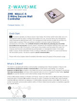
0% PWM1 + 100% PWM2
ALL ON/OFF button, broadcast to turn on/off all
LED indicator
Decrease whole brightness Increase whole brightness
Save and recall 3 scenes
Color Wheel for adjusting relative
brightness between PWM1 and PWM2
100% PWM1 + 0% PWM2
50% PWM1 +50% PWM2
100% PWM1 + 0% PWM20% PWM1 + 100% PWM2
3 Groups
Operating the device Technical Data

Wiring diagram
AC 100-240V
AC Power
50/60Hz
Installation
L L N N
PRI:
Uin=100 -240VAC
Iin=15m A MAX
Out=Z-Wave Signal
SR-ZV9002T3
-CCT-US
SW1
Z-Wave Controller
V2
V1
V3
V3
V2
V1
V1
V4
COMMAND_CLASS_VERSION
COMMAND_CLASS_ASSOCIATION_GRP_INFO
COMMAND_CLASS_MULTICHANNEL_ASSOCIATION
COMMAND_CLASS_CENTRAL_SCENE
COMMAND_CLASS_ASSOCIATION
COMMAND_CLASS_POWERLEVEL
COMMAND_CLASS_DEVICE_RESET_LOCALLY
COMMAND_CLASS_FIRMWARE_UPDATE_MD
YES
YES
YES
YES
YES
YES
YES
YES
/