Page is loading ...

Function introduction
Important: Read All Instructions Prior to Installation
Product Data
Safety & Warnings
• This device contains a button lithium battery that shall be stored and disposed properly.
• DO NOT expose the device to moisture.
Quick Start
How to install:
• Step 1: turn on your remote control.
• Step 2: activate inclusion mode on your Z-Wave controller.
• Step 3: activate inclusion mode of your remote control by pressing and holding down both buttons and of
Group 2 together over 3 seconds.
Product Description
The remote control is a Z-Wave device that can both control other Z-Wave devices and activate scenes in
Gateways. The remote control may be used with all devices certified with the Z-Wave Plus certificate and
should be compatible with such devices produced by other manufacturers.
Although it is controlling other devices, the device cannot act as Z-Wave network controller (primary or
secondary) and will always need a Z-Wave network controller to be included into a Z-Wave network. It also
supports the Over The Air (OTA) feature for the product’s firmware upgrade.
The remote control has following functions:
1. Control of groups of other Z-Wave devices using 'ON', 'OFF' and Dim commands.
2. Activation of scenes in Gateway mode.
The encryption modes that the remote control supports are S0, S2 Authenticated, S2 Unauthenticated. When
the remote control is being included into a Z-Wave network, you can use your primary controller/gateway to
enable one encryption mode or disable encryption. (The primary controller/gateway shall support encryption
mode configuration).
09.ZV9001K8.04772
Installation Guide
Please read carefully the enclosed user manual before installation of remote control, in order to ensure an
error-free functioning.
The remote control unit supplied as complete set for flush mounting in the standard circular European wall
boxes with 60mm diameter.
Inclusion (Adding to a Z-Wave network)
Step 1. Make sure the remote control does not belong to any Z-Wave network, short press any button, if LED
indicator does not turn on, the remote control does not belong to any network, then continue step 2,if LED
indicator turns on, it means the remote control has already been included to a network, please first set the
remote control to exclusion mode (refer to the part "Exclusion" of this manual),then continue step 2.
Step 2. Set primary controller/gateway into inclusion mode (Please refer to your primary controllers manual on
how to turn your controller into inclusion).
Step 3. Press and hold down both buttons and of Group 2 over 3 seconds, LED indicator turns on, the
remote control will be set to inclusion mode, and waiting to be included, after 10s LED indicator blinks 6 times
quickly to indicate successful inclusion. The remote control is a sleepy device, after inclusion it will not enter
into sleepy mode immediately, and will continue activation status for 30s and wait data interaction from the
gateway, the LED indicator will stay solid on, please be patient to wait LED indicator to turn off.
Exclusion (Removing from a Z-Wave network)
There are two exclusion methods:
Method 1: Exclusion from the primary controller/gateway as follows:
1. Set the primary controller/gateway into exclusion mode (Please refer to your primary controllers manual on
how to set your controller into exclusion).
2. Press and hold down both buttons and of Group 2 over 3 seconds, LED indicator turns on, the remote
control will be set to exclusion mode, and waiting to be excluded, after 7s LED indicator blinks 4 times quickly to
indicate successful exclusion.
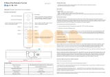
NAMRON Z-WAVE 4 KANALER BRYTER
Front side
Back side
Z-Wave Frequency
Power Supply
Operating temperature
Relative humidity
Dimensions
Waterproof Grade
868.42MHz
3VDC(1xCR2450 battery)
0 to 40°C
8% to 80%
71.2x71.2x13.6mm
IP20
Group 3 Group 3
Group 2:
Click to turn on, Press and
hold down to increase light
intensity
Group 2:
Click to turn off, Press and
hold down to decrease light
intensity
Press and hold down both keys together for 3s to be added to or
removed from Z-Wave network by Z-Wave master (primary) controller.
Group 4 Group 4
Group 5 Group 5
55.57 mm
71.20 mm
11 mm
Battery: CR2450
Before the first use, please open the battery
cover and remove the protective film
55.57 mm
71.20 mm

Method 2: Factory reset the remote control will force the remote control to be excluded from a network. (please
refer to the part “Factory Reset” of this manual)
How to check whether the remote control already included to a network
Short press any button, if LED indicator blinks 3 times, the remote control does not belong to any network, if
LED indicator turns on, it means the remote control has already been included to a network.
If the remote control already belongs to a network, follow the exclusion process before including it in your
network. Otherwise inclusion of this device will fail.
Factory Reset
Press and hold down both buttons and of Group 2 for over 10 seconds, LED indicator turns on and then
blinks 4 times quickly to indicate successful factory reset. Please use this procedure only when the network
primary controller is missing or otherwise inoperable.
Association
Z-Wave devices control other Z-Wave devices. The relationship between one device controlling another device
is called association. In order to control a different device, the controlling device needs to maintain a list of
devices that will receive controlling commands. These lists are called association groups and they are always
related to certain events (e.g. button pressed). In case the event happens all devices stored in the respective
association group will receive a common wireless command.
Association Groups:
Each group supports maximum 5 nodes for association, the same device can be associated with multiple
groups on the remote control simultaneously, to ensure better control experience, the remote control shall
remove the associated devices that are not under working status from association groups in time.
Association
Groups
Group
Name
Max
Nodes Description
Group 1 Lifeline 5
1. Send Command Class "Device Reset Locally Notification V1" to
associated devices of this group to report factory reset information
when factory reset the remote control.
2. When remote control battery power value changes, send
Command Class "Battery Report V1" to associated devices of this
group to report power value information.
3. Short press or press and hold down any button to send scene
activation command to the associated devices of this group using
Command Class “Central Scene Notification V3”
Group 2 Launch 1 5
Short press / button of Group 2 to send ON/OFF command to
associated devices of this group using Command Class "Basic Set
V2".
Press and hold down / button of Group 2 to send light intensity
increase/decrease command to associated devices of this group
using Command Class "Multilevel V4".
Group 3 Launch 2 5
Short press / button of Group 3 to send ON/OFF
command to associated devices of this group using
Command Class "Basic Set V2".
Press and hold down / button of Group 3 to send
light intensity increase/decrease command to
associated devices of this group using Command Class
"Multilevel V4".
Set and unset associations:
(Note: All association information will be cleared automatically once the remote control is excluded from a
network.)
There are two methods to set associations:
1. Set association by operating primary controller/gateway to send association command to the remote control:
When set association from primary controller/gateway, the remote control shall be activated first, if it is not
activated, you should activate it manually.
The primary controller/gateway sends association command to the remote control using “Command Class
ASSOCIATION” or “Command Class Multi Channel Association”
2. Set association by operating the remote control and devices to be controlled:
To control a Z-Wave device from the remote control the node ID of this device needs to be assigned to one of
the two association groups. This is a three-step process:
1. Press and hold down both buttons and of Group 2 over 3 seconds, LED indicator turns on.
2. Short press ON button of any group within 7s to associate the device to this group, short press OFF button of
any group within 7s to remove association of the device from this group.
3. Operate the device to be controlled to send Node Information Frame (please refer to the device manual)
within 10 seconds, or set the device to exclusion mode within 10 seconds, since it will send Node Information
Frame in exclusion mode, LED indications are as follows:
Group 4 Launch 3 5
Short press / button of Group 4 to send ON/OFF
command to associated devices of this group using
Command Class "Basic Set V2".
Press and hold down / button of Group 4 to send
light intensity increase/decrease command to
associated devices of this group using Command Class
"Multilevel V4".
Group 5 Launch 4 5
Short press / button of Group 5 to send ON/OFF
command to associated devices of this group using
Command Class "Basic Set V2".
Press and hold down / button of Group 5 to send
light intensity increase/decrease command to
associated devices of this group using Command Class
"Multilevel V4".

Operating the device
• Short press or press and hold down any button to send scene activation command to association group 1
using Command Class “Central Scene Notification V3”.
• Short press / button of Group 2, send ON/OFF command to all associated devices of Association Group
2.
• Press and hold down / button of Group 2, send light intensity increase/decrease command to all
associated devices of Association Group 2.
• Short press / button of Group 3, send ON/OFF command to all associated devices of Association Group
3.
• Press and hold down / button of Group 3, send light intensity increase/decrease command to all
associated devices of Association Group 3.
• Short press / button of Group 4, send ON/OFF command to all associated devices of Association Group
4.
• Press and hold down / button of Group 4, send light intensity increase/decrease command to all
associated devices of Association Group 4.
• Short press / button of Group 5, send ON/OFF command to all associated devices of Association Group
5.
• Press and hold down / button of Group 5, send light intensity increase/decrease command to all
associated devices of Association Group 5.
Technical Data
Battery Type
Frequency
Wireless Range
SDK
Explorer Frame Support
Device Type
Generic Device Class
Specific Device Class
Routing
FLiRS
1*CR2450
868.42 MHz
up to 100 m outside, on average up to 40 m inside buildings
6.71.01
Yes
Wall Controller
Switch Remote
Switch Remote Multilevel
No
No
Z-Wave Plus Info
Parameter
Z-Wave Plus Version
Role Type
Node Type
Installer Icon Type
User Icon Type
Value
1
Slave Portable
ZWAVEPLUS
0x0b00 (ICON_TYPE_GENERIC_REMOTE_CONTROL_SIMPLE)
0x0b00 (ICON_TYPE_GENERIC_REMOTE_CONTROL_SIMPLE)
How to communicate with the device
The remote control is under sleepy mode for most of the time to save battery power. It can not receive wireless
command under sleepy mode. Before the gateway interacts data with the remote, the remote control shall be
activated manually first. Short press any button to activate the remote control for 3s, and press and hold down
and buttons of Group 2 over 1 second to activate the remote control for 7s.
Node Information Frame
The Node Information Frame is the business card of a Z-Wave device. It contains information about the device
type and the technical capabilities. The inclusion and exclusion of the device is confirmed by sending out a
Node Information Frame. Beside this it may be needed for certain network operations to send out a Node
Information Frame.
How to send out Node Information Frame:
Set the wall controller into inclusion/exclusion mode: and press and hold down and buttons of Group 2
over 3 seconds, LED indicator turns on to indicate the wall controller has already sent out Node Information
Frame, the user can repeat the operation to set the wall controller to quit “inclusion/exclusion mode”.
LED blinks twice to indicate that the remote control failed to add the associated device (the association group
has already added maximum quantity associated devices that it supports ).
LED blinks 5 times to indicate that the remote control added the associated device successfully.
LED blinks 8 times to indicate that the remote control removed the associated device successfully.
To remove all associated devices in an association group on the remote control directly:
1. Press and hold down both buttons and of Group 2 over 3 seconds, LED indicator turns on.
2. Click OFF button of any group on the remote control 5 times continuously within 7 seconds to remove all
associated devices of this group, LED indicator blinks 8 times to indicate that the associated devices are
removed successfully.
Group 3 Group 3
Group 2:
Click to turn on, Press and
hold down to increase light
intensity
Group 2:
Click to turn off, Press and
hold down to decrease light
intensity
Press and hold down both keys together for 3s to be added to or
removed from Z-Wave network by Z-Wave master (primary) controller.
Group 4 Group 4
Group 5 Group 5
Manufacturer Specific
Parameter
Manufacturer ID
Product Type ID
Product ID
Value (hex)
0x0330
0x0003
0xa305

SUPPORTED COMMAND CLASS
• COMMAND_CLASS_ZWAVEPLUS_INFO_V2
• COMMAND_CLASS_ASSOCIATION_V2
• COMMAND_CLASS_MULTI_CHANNEL_ASSOCIATION_V3
• COMMAND_CLASS_CENTRAL_SCENE_V3
• COMMAND_CLASS_ASSOCIATION_GRP_INFO_V1
• COMMAND_CLASS_TRANSPORT_SERVICE_V2
• COMMAND_CLASS_VERSION_V2
• COMMAND_CLASS_MANUFACTURER_SPECIFIC_V2
• COMMAND_CLASS_DEVICE_RESET_LOCALLY_V1
• COMMAND_CLASS_FIRMWARE_UPDATE_MD_V4
• COMMAND_CLASS_POWERLEVEL_V1
• COMMAND_CLASS_BATTERY_V1
• COMMAND_CLASS_SECURITY_V1
• COMMAND_CLASS_SECURITY_2_V1
• COMMAND_CLASS_WAKE_UP_V2
• COMMAND_CLASS_SUPERVISION_V1
• COMMAND_CLASS_CONFIGURATION_V1
Controlled Command Classes
• COMMAND_CLASS_CENTRAL_SCENE_V3
• COMMAND_CLASS_BASIC_V2
• COMMAND_CLASS_SWITCH_MULTILEVEL_V4
• Multi Channel V3
• Security_V1
• Security_2_V1
①
silicone gel battery cover
Use tool to open the
1.Remove battery insulator
2.Install the controller to wall(2 methods)
Method 1:Stick 3M glue on the
back of the bracket and then stick
the bracket to the wall
Method 2:Screw the bracket
to the wall
After the bracket is fixed,clip
the frame and control part to the
bracket in sequence
②Pull out the
battery insulator
③Install the silicone
battery cover back
Installation
Importer:
Namron AS
Nedre kalbakkvei 88B
1081 Olso
Norway
Made in China
Size Descriptio n Defaul t Valu e
Para mete r
HEX (DEC)
1. Value=0x55AA, other values
are invalid, factory reset the
wall controller
2
0x01(1)
(Only write in parameter,
no report feedback when
get the parameter)
Configuration Command Class
/