Page is loading ...

!1
Key Ring Controller KFOB2
Quick Start
Please refer to the chapters below for detailed information about all aspects of the products usage.
The device operates in normal control mode or in management mode. Pushing all four buttons
for 5 sec. will turn the device into management mode (indicated by blinking green LED). The
management mode will time out after 10 seconds if no further button is pushed. Button 3
confirms standard inclusion or exclusion started by a primary controller, button 2 issues a
Node Information Frame or wakeup notification, button 4 is used to add devices into association
groups and button 1 confirms inclusion or exclusion in NWI (network wide inclusion) mode.
What is Z-Wave?
This device is equipped with wireless
communication complying with the Z-Wave
standard. Z-Wave is the international standard
for wireless communication in smart homes and
buildings. It is using the frequency of 868.42
MHz (EU) or 908 MHz (US) to realize a very stable
and secure communication between devices of
different origin, type and brand. Each message is
reconfirmed (two-way communication) and every
mains powered node can act as a repeater for
other nodes (meshed network) in case the
receiver is not in direct wireless range of the
transmitter.
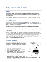
Z-Wave
differentiates
between
Controllers and
Slaves. Slaves
are either
sensors (S) trans-
mitting metered or
measured data or
actuators (A) capable to execute an action.
Controllers are either static mains powered
controllers (C) also referred to as gateways or
mobile battery operated remote controls (R). This
results in a number of possible communication
patterns within a Z-Wave network that are partly or
completely supported by a specific device.
1. Controllers control actuators.
2. Actuators report change of status back to
controller.
3. Sensors report change of status of
measured values to controller.
4. Sensors directly control actuators.
5. Actuators control other actuators.
6. Remote controls send signals to static
controllers to trigger scenes or other
actions.
7. Remote controls control other actuators.
Product description
The Z-Wave.Me Key Fob is a Z-Wave device that
can both control other Z-Wave devices and
activate predefined scenes in an IP gateway.
Although it is controlling other devices, the KFOB
can’t act as Z-Wave network controller (primary or
secondary) and will always need a Z-Wave network

!
2
controller to be included into a Z-Wave network.
The device can be used in different modes that are
selected by configuration parameters:
1. Control of groups of other Z-Wave devices
using ‘ON’, ‘OFF’ and Dim commands.
2. Control of devices in proximity of the FOB
using ‘ALL ON’ or ‘ALL OFF’ commands.
3. Control of a device in proximity of the FOB
using ‘ON’ and ‘OFF’ commands.
4. Activation of predefined scenes in Gateways or
other Z-Wave devices.
Installation Guidelines
The device comes ready to use with a battery
already installed. On factory default the device is
not included in any network and any button push
will result in a long red blink indicating an error.
This behavior can be used to test the factory
default or exclusion state.
For battery change, the device needs to be opened
by removing the three little screws on the backside
of the device. During reassembly, watch the
position of the white rubber and make sure the
silver buttons fit exactly into the nipples of the
rubber.
The device can be operated in two different modes:
• Operation Mode: This is the mode where the
device is controlling other Z-Wave devices or
is activating scenes.
• Management Mode: The device is turned into
the management mode by pushing all four
buttons for 5 sec. A blinking green LED
indicates the management mode. In the
management mode the buttons of the device
have different functions. If no further action is
performed the device will turn back to the
normal mode after 10 sec. Any management
action terminates the management mode as
well.
In management mode the following actions can be
performed:
• Button 1 - Network Wide Inclusion: The
device can be included into a Z-Wave
Network from any physical location in the
network. This requires a primary controller
supporting Explorer Frames. This mode lasts
for 20 seconds and stops automatically. Any
button press stops the mode as well.
• Button 2 - Send Node Information Frame and
Wake up Notification. (See explanation in the
respective chapters below)
• Button 3 – Standard Inclusion/Exclusion
Mode: The device is included or excluded
from a controller in direct wireless range. Any
button press stops the mode. Performing an
exclusion of the device from a network resets
the device into its factory default.
• Button 4 - Association Set: To assign target
devices to one of the four association groups.
Refer to the manuals section about
association for more information how to set
and unset association groups.
Behavior within the Z-Wave network
On factory default, the device does not belong to
any Z-Wave network. The device needs to join an
existing wireless network to communicate with the
devices of this network. This process is
called Inclusion. Devices can also leave a
network. This process is called Exclusion. The
primary controller of the Z-Wave network initiates
both processes. This controller will be turned into
exclusion respective inclusion mode. Please refer
to your primary controllers manual on how to turn
your controller into inclusion or exclusion mode.
Only if the primary controller is in inclusion or
exclusion mode, this device can join or leave the
network. Leaving the network - i.e. being excluded -
sets the device back to factory default.
Z-Wave knows two types of inclusion processes: The standard
inclusion requires that both controller and the device to be
included are in physical proximity of few meters. The network
wide inclusion allows including a device on every position in
the network as long as there is at least one wireless
connection to a device already included in the network. This
function however requires that both controller and the device to
be included support so-called explorer frames. Please refer to
the technical data of the devices for more information about
explorer frame support.
If the device already belongs to a network, follow
the exclusion process before including it in your
network. Otherwise inclusion of this device will fail.
Once the controller is turned into
standard inclusion mode, turn the Key
Fob into management mode and hit
Button 3. Entering management mode and hitting
button 3 when the controller is in exclusion mode

!
3
exclude the device. To include/exclude the device
in the Network Wide Inclusion Mode turn the
KFOB into management mode and hit Button 1.
Operating the device
Depending on the button mode and command set
configured the key fob can be used in different
ways.
Button modes:
Control with two groups of two buttons (This is
the default mode) One group (No. 1) of devices is
controlled by button 1 and 3, the other group (No.
2) is controlled by button 2 and 4. Clicking the
larger button turns the loads ’ON’, clicking the
smaller button turns the loads ‘OFF’. If double
clicks are enabled in configuration parameters #1
or #2, groups No 3 and No 4 are controlled by short
double click of the buttons.
Dimming commands are sent by holding down the
buttons (Dim UP using Buttons 1 and 2, Dim Down
using Buttons 3 and 4) respective Click + Hold in
case the double click option is enabled.
Control with single buttons In this mode a group
of devices is controlled by a single button: single
click turns ‘ON’; double click turns ‘OFF’ devices in
the group. In case dimmers are controlled, holding
down the button will dim up, click and hold down
will dim down the load. The group number
corresponds to the button label.
Control Commands:
The configuration parameter #11…#14 specifies
what commands are sent when the buttons are
operated.
Direct Control of associated devices using ‘ON’,
‘OFF’, ‘DIM UP’ and ‘DIM DOWN’
(This is the default mode No. 1). Devices in
association groups are controlled using Basic ‘ON’
and ‘OFF’ commands and Dim Start/Stop
commands. This mode implements the
communication pattern 7. The parameter value No.
2 disables the use of Dim commands.
Control of Devices in proximity
Basic ‘ON’, ‘OFF’ and Dim Start/Stop commands
are sent to the device nearest to the Fob. (50...100
cm) Attention: In case there is more than one Z-
Wave device nearby all these devices may be
switched. For this reason the proximity function
should be handled with care. This mode
implements the communication pattern 7.
Control of neighboring devices using the ‘ALL
ON’ and ‘ALL OFF’ commands.
The special commands ‘ALL ON’ resp. ‘ALL OFF’
are sent as broadcast to all devices in direct
wireless range. The devices act according to their
individual settings for ‘Switch ALL’ commands. This
mode implements the communication pattern 7.
Simple Scene Activation using configurable
scene control commands
Associated devices in an association group are
controlled by individual commands defined by Z-
Wave command class ‘Scene Controller
Configuration’. One scene number can be
configured per association group. On default, the
scene number equals the association group
number as shown in the figure below. This mode
implements communication patterns 6 and 7. This
mode is typically used to activate scenes in IP
gateways but can also be used to activate
predefined scenes in other scene-capable devices.

!
4
Enhanced Scene Activation
In this mode every button action can issue a scene
activation command with a dedicated number. The
scene number is a combination of the group
number and the action performed on the button and
has always two digits. The group number defines
the upper digit of the scene number, the action the
lower digit. The following actions are possible:
• 1 = On
• 2 = Off
• 3 = Dim Up Start
• 4 = Dim Down Start
• 5 = Dim Up Stop
• 6 = Dim Down Stop
Example: Clicking/double clicking the button 1 will
issue a scene activation command for scene 11
(button 1 click, event on) and scene 12 (button
double click 1, event off, single button control is
used in this example). This mode implements the
communication pattern 6.
Child Protection
The device can be turned into a child protection
mode. In this mode all local operation is disabled.
The child protection mode MUST be turned on
wirelessly. However, in protected by sequence
mode it is possible to unlock the device for local
operation by pressing any button for 5 seconds.
The unlock state will last for 5 seconds.
Wakeup Intervals - how to
communicate with the device?
This device is battery operated and turned into
deep sleep state most of the time to save battery
power. Communication with the device is limited. In
order to communicate with the device, a static
controller C is needed in the network. This
controller will maintain a mailbox for the battery
operated devices and store commands that cannot
be received during deep sleep state. Without such
a controller, communication may become
impossible and/or the battery lifetime is significantly
decreased.
The device will stay awake right after
inclusion for 2.5 seconds allowing the
controller to perform certain
configuration actions. It is possible to manually
wake up the device by pushing button 2 in
management mode.
The minimum allowed wakeup time is 240s but it’s
strongly recommended to define a much longer
interval since the only purpose of a wakeup should
be the reporting of the battery status or an update
of the child protection settings. Defining Node id of
0 as a destination of the Wakeup Notification will
disable the periodical wakeup function entirely.
It is possible to set the node ID to 255 to send wakeup notifications as
broadcast. In this mode device takes more time to go to sleep and drains
battery faster, but can notify all it's direct neighbors about a wakeup.
Node Information Frame
The Node Information Frame is the business card
of a Z-Wave device. It contains information about
the device type and the technical capabilities. The
inclusion and exclusion of the device is confirmed
by sending out a Node Information Frame. Beside
this it may be needed for certain network
operations to send out a Node Information Frame.
Pressing Button 2 in management mode will issue
a Node Information Frame.
LED Control
• Confirmation - green 2 sec
• Failure - red 2 sec
• Button press confirmation - green 1/4 sec
• Waiting for Network Management mode
selection - green blinks
• Waiting for group selection in Association
Set Mode - green fast blink
• Waiting for NIF in Association Set Mode -
green-red-off blink
Associations
Z-Wave devices control other Z-Wave devices. The
relationship between one device controlling another
device is called association. In order to
control a different device, the
controlling device needs to maintain a
list of devices that will receive
controlling commands. These lists are
called association groups and they are always
related to certain events (e.g. button pressed,
sensor triggers,...). In case the event happens, all
devices stored in the respective association group
will receive a common wireless command.
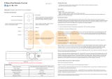
Association Groups
1
By button 1 or single clicks of buttons 1 and 2 (max 8 nodes)
2
By button 2 or double clicks of buttons 3 and 4 (max 8 nodes)
3
By button 3 or single clicks of buttons 1 and 2 (max 8 nodes)

!
5
4
By button 4 or double clicks of buttons 3 and 4 (max 8 nodes)
The IP gateway that will receive the scene
activation commands must be placed on all
association groups.
Set and unset associations to actuators
Associations can be assigned and removed either via Z-
Wave commands or using the device itself.
To control a Z-Wave device from the Key Fob, the Node
id of this device needs to be assigned to one of the four
association groups. This is a three-step process:
1. Turn the Key Fob into management mode and hit
button 4 within 10 sec. (LED is blinking green when
management mode is reached).
2. Within 10 sec. push the button of the Key Fob you
like the Z-Wave actuator to be controlled with. After
10 sec. the devices goes back to sleep. Single click
means adding to this association group, double
click means removing the node selected in step
(3) from this association group.
3. Find the Z-Wave actuator you like to control by the
device. Hit the button on the device to issue a Node
Information Frame within 20 sec. A common way is
hitting a control button one or three times. Please
consult the manual of the device to be controlled for
more information how to issue a Node Information
Frame. Any button press on Key Fob at this stage will
terminate the process.
Configuration Parameters
Z-Wave products are supposed to work out of the
box after inclusion, however certain configuration
can adapt the function better to user needs or
unlock further enhanced features.
Pair Mode for Button 1 and 3
(Parameter Number 1)
Pair Mode for Button 2 and 4
(Parameter Number 2)
Value
Description
0
Separately
1
In pair without double clicks (Default)
2
In pair with double clicks
Control Commands on Group 1
(Parameter Number 11)
Control Commands on Group 2
(Parameter Number 12)
Control Commands on Group 3
(Parameter Number 13)
Control Commands on Group 4
(Parameter Number 14)
Value
Description
0
Disabled
1
Switch On/Off and Dim (send Basic Set and Multilevel)
(Default)
2
Switch On/Off only (send Basic Set)
3
Switch All
4
Send Scenes
5
Send Preconfigured Scenes
6
Control devices in proximity
Typical click timeout
(Parameter Number 20)
Typical time used to differentiate click, hold and
double click
Value
Description
1 — 100
in 10ms units (Default 50)
Send the following Switch All commands
(Parameter Number 21)
Value
Description
1
Switch off only (Default)
2
Switch on only
255
Switch all on and off
Invert buttons
(Parameter Number 22)
Value
Description
0
No (Default)
1
Yes
LED confirmation mode
(Parameter Number 24)
This allows saving battery power
Value
Description
0
No confirmations
1
Confirm button press
2
Confirm button press and delivery (Default)
Send unsolicited Battery Report on Wake Up
(Parameter Number 30)

!6
Value Description
0 No (Default)
1 To same node as wake up notification
2 Broadcast to neighbors
Batteries
The unit is operated by batteries. Use only
batteries of correct type. Never mix old and
new batteries in the same device. Used
batteries contain hazardous substances and
should not be disposed of with household
waste!
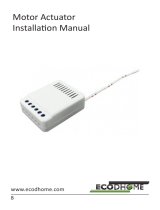
Technical Data
!
IP Rating IP 20
Battery Type 1 * CR2032
Frequency
EU: 868.4 MHz (EN 300 220) or
RU: 869.0 MHz (GKRCh/EN 300 200) or
US: 908.4 MHz (FCC CFR47 P 15.249)
Wireless Range Up to 100 m outside, on average up to 20 m
inside buildings
Explorer Frame
Support
Yes
SDK 4.54 pl1
Device Type Slave with routing capabilities
Specific Device Class Multilevel Remote Switch
Routing No
FLiRS No
Firmware Version 1.3
Dimensions 50 x 30 x 10 mm
Weight 30 gr.
Z-Wave.Me guarantees that every device is free from
physical defects in material and workmanship under
normal use for one year from the date of purchase. If
the product proves defective during this one-year
warranty period, Z-Wave.Me will replace it free of
charge. Z-Wave.Me does not issue any refunds. This
warranty is extended to the original end user
purchase only and is not transferable. This warranty
does not apply to: (1) damage to units caused by
accident, dropping or abuse in handling, or any
negligent use; (2) units which have been subject to
unauthorized repair, taken apart, or otherwise
modified; (3) units not used in accordance with
instruction; (4) damages exceeding the cost of the
product; (5) transit damage, initial installation costs,
removal cost, or reinstallation cost. For information on
additional devices, please visit us online.
This equipment has been tested and found to
comply with the limits for a Class B digital
device, pursuant to Part 15 of the FCC Rules.
These limits are designed to provide reasonable
protection against harmful interference in a
residential installation. This equipment
generates, uses and can radiate radio frequency
energy and if not installed and used in
accordance with the instructions, may cause
harmful interference to radio communications.
However, there is no guarantee that interference
will not occur in a particular installation. If this
equipment does cause harmful interference to
radio or television reception, which can be
determined by turning the equipment off and on,
the user is encouraged to try to correct the
interference by one or more of the following
measures:
(1) Reorient or relocate the receiving antenna.
(2) Increase the separation between the
equipment and receiver. (3) Connect the
equipment into an outlet on a circuit different
from that to which the receiver is connected. (4)
Consult the dealer or an experienced radio/TV
technician for help. Any changes or modification
not expressly approved by the party responsible
for compliance could void the user's authority to
operate the device.
Where shielded interface cables have been
provided with the product or specified additional
components or accessories elsewhere defined to
be used with the installation of the product, they
must be used in order to ensure compliance with
FCC regulations.
CE for Class B ITE (Following European standard
EN55022/1998; EN61000- 3-2/1995; EN61000-
3-3/1995, EN55024/1998, EN60950-1/2001)
!
/