Devolo MT:2653 User manual
- Category
- Gateways/controllers
- Type
- User manual

Devolo MT:2653
Quick Start
C This remote control has two modes:
the normal operation for daily use
and management mode for setup. Pushing all
four buttons for 1 sec. turns the device into
management mode (indicated by slow blinking
green LED). Management mode time-out is 10
sec.
In factory default mode pushing one of the four
buttons for 1 sec will start different inclusion
modes:
• Button 1: Include (Add) KFOB as sec.
controller
• Button 2: Include (add) KFOB as
secondary controller - non secure
• Button 3: Include (add) new device into
KFOBS network
• Button 4: Include (add) new device into
KFOBS network - non secure
The process for button 1 and 2 are indicated
with fast red/green blinking, the process for
button 3 and 4 show a fast green blinking. Every
button push stops the process. This fast
inclusion only works when device is in
factory default. Once one device is included or
the fob is included as secondary controller
further inclusion and exclusion operation require
to turn the device into management mode. In
management mode
• Button 1: Include or Exclude the device as
secondary controller
• Button 2: Issue Wakeup Notification and
send out Node Information Frame
• Button 3 followed by short click of button
1: Start Secure Inclusion
• Button 3 followed by short click of button
2: Start Unsecure Inclusion
• Button 3 followed by short click of button
3: Start Exclusion
• Button 3 followed by short click of button
4: Start Primary Handover
Attention: For convenience reason some special
short cut apply IF and only IF the KFOB is the
primary controller of the network: The first
device included into a button group will
define the commands sent out by this group
regardless of the default value of the
configuration parameters 11-14. If the device is
a door lock the button group will turn into door
lock control (value=7). For dimmers and motor
controls the value changes into Multilevel Switch
Control (value=1). All other devices will turn the
button group into Basic control (value=2). All
configuration values can be changed if needed.
When KFOB is primary controller the very first
device included will be automatically put
into button group A and the command set will
change according to the rules just mentioned. All
other devices need ot be put in button groups
manually.
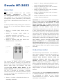
Product description
The Secure Key Fob Controller is a 4 button Z-
Wave device capable to act both as primary or
secondary controller. The four buttons can
control other Z-Wave devices such as
switches, dimmer and even door locks
directly. Various options - configurable by Z-
Wave configuration commands - define the
actions and the commands used for this control.
It is possible to use two sets of buttons (one of
on/open/up and one for off/closed/down) or 4
single buttons to control 4 different groups of
devices.
The controller also allows triggering scenes in
a central controller. Again different modes can
be configured to adapt to the various
implementations of scenes in different central
controllers in the market.

Control options also include special modes like
'all on/off' or always controlling the Z-Wave
device in proximity to the fob.
The device supports secure
communication when included with enhanced
security option and when communicating to a
device also supporting enhanced security option.
Otherwise the device will automatically turn into
normal communication. to maintain backward
compatibility.
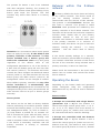
Installation Guidelines
The device comes ready to use with a battery
already installed.
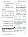
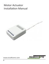
For battery change the
device needs to be
opened by removing the
three little screws on the
backside of the device.
Use a screwdriver or any
other usable device to
gently push out the
battery as shown on the picture. During
reassembly watch the position of the white
rubber and the make sure the silver buttons fit
exactly into the nipples of the rubber.
The device can be operated in two different
modes: the operation mode and the
management mode:
• Operation Mode: This is the mode where
the device is controlling other devices.
• Management Mode: The device is turned
into the management mode by pushing
all four buttons for one second. A
blinking LED indicates the management
mode. In the management mode buttons
of the device have different functions. If
no further action is performed the device
will turn back to the normal mode after 10
sec. Any management action terminates
the management mode as well.
In management mode the following actions can
be performed:
• Button 1 - Inclusion/Exclusion: Every
inclusion or exclusion attempt is confirmed
by hitting this button. Single Click is used
for standard inclusion and exclusion,
double click is used for network wide
inclusion. With this operation the device
can be included into a Z-Wave Network
from any physical location in the network.
This requires a primary controller
supporting network wide inclusion. This
mode lasts for 20 seconds and stops
automatically. Any button press stops the
mode as well.
• Button 2 - Send Node Information Frame
and Wake up Notification. (see explanation
below)
• Button 3 - Activates the primary
controller management menu. The
following sub menu items are available:
• Button 3 followed by short click
of button 1: Start Secure Inclusion
(Add)
• Button 3 followed by short click
of button 2: Start Unsecure
Inclusion (Add)
• Button 3 followed by short click
of button 3: Start Exclusion
(Remove)
• Button 3 followed by short click
of button 4: Start Primary
Handover
• Button 3 followed by pushing
button 4 for 5 seconds: Factory
Default Reset. After clicking on
button 3 keep button 4 pushed for 4
seconds
• Button 4 - Enter into Association mode to
assign target devices to one of the four
associations. Refer to the manuals section
about association for more information
how to set and unset association groups.
In factory default mode pushing one of the four
buttons for 1 sec will start different inclusion
modes:
• Button 1: Include KFOB as secondary
controller
• Button 2: Include KFOB as secondary
controller - non secure
• Button 3: Include new device into KFOBS
network
• Button 4: Include new device into KFOBS
network - non secure

The process for button 1 and 2 are indicated
with fast red/green blinking, the process for
button 3 and 4 show a fast green blinking. Every
button push stops the process. This fast
inclusion only works when device is in factory
default.
Attention: For convenience reason some special
short cut apply IF and only IF the KFOB is the
primary controller of the network: The first
device included into a button group will
define the commands sent out by this group
regardless of the default value of the
configuration parameters 11-14. If the device is
a door lock the button group will turn into door
lock control (value=7). For dimmers and motor
controls the value changes into Multilevel Switch
Control (value=1). All other devices will turn the
button group into Basic control (value=2). All
configuration values can be changed if needed.
When KFOB is primary controller the very first
device included will be automatically put
into button group A and the command set will
change according to the rules just mentioned. All
other devices need ot be put in button groups
manually.
Factory Reset
The device can be set back to factory defaults
without performing an exclusion process. Please
executes the following steps: (1) Turn the device
into Management Mode, (2) click on Button 3,
(3) keep button 4 pushed for 10 seconds. For
first 5 seconds the green LED will blink, then it
turns into long red/shot green blinking until
reset is complete. Please use this procedure only
if the device is secondary controller and the
primary controller is missing or otherwise
inoperable.
Behavior within the Z-Wave
network
I On factory default the device does not belong
to any Z-Wave network. The device needs to
join an existing wireless network to
communicate with the devices of this network.
This process is called Inclusion. Devices can
also leave a network. This process is called
Exclusion. Both processes are initiated by the
primary controller of the Z-Wave network. This
controller will be turned into exclusion respective
inclusion mode. Please refer to your primary
controllers manual on how to turn your
controller into inclusion or exclusion mode. Only
if the primary controller is in inclusion or
exclusion mode, this device can join or leave the
network. Leaving the network - i.e. being
excluded - sets the device back to factory
default.
If the device already belongs to a network,
follow the exclusion process before including it in
your network. Otherwise inclusion of this device
will fail. If the controller being included was a
primary controller, it has to be reset first.
Please check the instructions in the quick start
section how to include and exclude the device
from a network.
Operating the device
Depending on the button mode and operating
modes configured using the configuration
parameters the key fob can be used in different
ways.
Button modes:
4 Groups are controlled with single button
(parameter 1/2 = 0) The four buttons 1-4
control one single control group each: 1->A, 2-
>B, 3->C, 4->D. Single click turns devices in
the control group on, double click turns them
off. Click and hold can be used for dimming.
2 Groups are controlled with two buttons
(parameter 1/2 = 1) The buttons 1 and 3
control the control group A (button on turns on,
buttons turns off), the buttons 2 and 4 control
the control group B (button on turns on, buttons

turns off). In case dimmers are controlled,
holding down the larger button will dim up,
holding down the smaller button will dim down
the load. Releasing the button will stop the
dimming function.
4 Groups are controlled with two buttons
and double click (parameter 1/2 = 2) This
mode enhances the previous mode and allows to
control two further control groups C and D using
double clicks.
Operating modes:
The devices supports 8 different operating
modes - this means the kind of command sent
out when pushing a button. Operating modes
either directly control other devices or they issue
various scene activation commands to a central
controller. Operating modes for direct device
control are:
• Direct Control of associated devices
with On/Off/Dim commands
(parameter 11...14 = 1). Devices are
controlled using Basic Set On/Off
commands and Switch-Multilevel Dim
Start/Stop. This mode implements
communication pattern 7.
• Direct Control of associated devices
with only On/Off commands
(parameter 11...14 = 2). Devices are
controlled using only Basic Set On/Off
commands. On dimming Up event On is
sent, on dimming Down Off is sent. This
mode also implements communication
pattern7.
• Switch All commands (parameter
11...14 = 3) In this mode a all
neighboring devices will receive Switch-
All Set On/Off command and interpret it
according to their membership in Switch-
All groups. This mode implements
communication pattern 7.
• Direct Control of Devices in proximity
(parameter 11...14 = 6). Basic Set and
Switch-Multilevel Dim commands are sent
to a device in proximity (50...100 cm)
from the Fob. Attention: In case there are
more than one Z-Wave devices nearby all
these devices may be switched. For this
reason the proximity function should be
handled with care. This mode implements
communication pattern 7
• Door Lock Control (parameter 11...14
= 7) This mode allows direct control
(open/close) of electronic door locks using
secure communication. The mode
implements communication pattern 7.
Operating modes for scene activation are:
• Direct Activation of preconfigured
scenes (parameter 11...14 =
5) Associated devices in an association
group are controlled by individual
commands defines by Z-Wave command
class ‘Scene Controller Configuration’. This
mode enhances mode Direct Control of
associated devices with On/Off/Dim
commands and implements
communication patterns 6 and 7. Please
turn the button mode to 'separate' to allow
different a scene id on every button.
• Scene Activation in IP Gateway
(parameter 11...14 = 4) If configured
correctly the buttons can trigger a scene in
a gateway. The scene number triggered is
a combination of the group number and
the action performed on the button and
has always two digits. The group number
defines the upper digit of the scene
number, the action the lower digit. The
following actions are possible: 1 = On, 2 =

Off, 3 = Dim Up Start, 4 = Dim Down
Start, 5 = Dim Up Stop, 6 = Dim Down
Stop
Example: Clicking/double clicking the
button will issue scene triggers, scene 11
(button 1 click, event on), scene 12
(button double click 1, event off, single
button control is used in this example)
• Activation of Central Scenes
(parameter 11...14 = 8,Default) Z-
Wave Plus introduces a new process for
scene activation - the central scene
control. Pushing a button and releasing a
button sends a certain command to the
central controller using the lifeline
association group. This allows reacting
both on button push and button release.
This mode implements communication
patterns 6 but requires a central gateway
supporting Z-Wave Plus.
Child Protection
The device can be turn into a child protection
mode. In this mode all local operation is
disabled.
The child protection mode MUST be turned on
wirelessly. However in protected by sequence
mode it is possible to unlock the device for local
operation by pressing any button within 5 sec.
The unlock-state will last for 5 seconds.
Wakeup Intervals - how to
communicate with the device?
W This device is battery operated and turned
into deep sleep state most of the time to save
battery life time. Communication with the device
is limited. In order to communicate with the
device, a static controller C is needed in the
network. This controller will maintain a mailbox
for the battery operated devices and store
commands that can not be received during deep
sleep state. Without such a controller,
communication may become impossible and/or
the battery life time is significantly decreased.
This device will wakeup regularly and announce
the wakeup state by sending out a so-called
Wakeup Notification. The controller can then
empty the mailbox. Therefore, the device needs
to be configured with the desired wakeup
interval and the node ID of the controller. If the
device was included by a static controller this
controller will usually perform all necessary
configurations. The wakeup interval is a tradeoff
between maximal battery life time and the
desired responses of the device.
The device will stay awake right after inclusion
for 10 seconds allowing the controller to perform
certain configuration. It is possible to manually
wake up the device by pushing button 2 in
management mode.
The minimum allowed wakeup time is 240s but
it’s strongly recommended to define a much
longer interval since the only purpose of a
wakeup should be the reporting of the battery
status or an update of the child protection
settings. The device has a periodic wakeup
function however this function is disabled by the
configuration parameter #25. This will protect
the battery in case the controller is accidently
configuring a wakeup interval. A wakeup of the
fob outside the range of the controller will lead
to lots of unsuccessful communication attempts
draining the battery. Defining Node id of 0 as a
destination of the Wake up Notification will
disable the periodical wakeup function as well.
It is possible to set the node ID to 255 to send wakeup
notifications as broadcast. In this mode device takes more time
to go to sleep and drains battery faster, but can notify all it's
direct neighbors about a wakeup.
Node Information Frame
NIF The Node Information Frame is the
business card of a Z-Wave device. It contains
information about the device type and the
technical capabilities. The inclusion and
exclusion of the device is confirmed by sending
out a Node Information Frame. Beside this it
may be needed for certain network operations to
send out a Node Information Frame.
Pressing Button 2 in management mode will
issue a Node Information Frame.
LED Control

1. Confirmation - green 1 sec
2. Failure - red 1 sec
3. Button press confirmation - green 1/4 sec
4. Waiting for Network Management mode
selection - slow green blinks
5. Waiting for group selection in Association
Set Mode - green fast blink
6. Waiting for primary controller function
selection - green fast blink
7. Waiting for NIF in Association Set Mode -
green-red-off blink
Associations
A Z-Wave devices control other Z-Wave devices.
The relationship between one device controlling
another device is called association. In order to
control a different device, the controlling device
needs to maintain a list of devices that will
receive controlling commands. These lists are
called association groups and they are always
related to certain events (e.g. button pressed,
sensor triggers, ...). In case the event happens
all devices stored in the respective association
group will receive a common wireless command.
Association Groups:
1
Lifeline (max. nodes in group: 10)
2
Control Group A, controlled by button 1 or
single clicks of buttons 1 and 3 (max. nodes
in group: 10)
3
Control Group B, controlled by button 2 or
single clicks of buttons 2 and 4 (max. nodes
in group: 10)
4
Control Group C, controlled by button 3 or
double clicks of buttons 1 and 3 (max.
nodes in group: 10)
5
Control Group D, controlled by button 4 or
double clicks of buttons 2 and 4 (max.
nodes in group: 10)
Set and unset associations to
actuators
Associations can be assigned and remove either
via Z-Wave commands or using the device itself.
To control a Z-Wave device from the Key Fob
the node ID of this devices needs to be assigned
to one of the four association groups. This is a
three-step process:
1. Turn the Key Fob into management mode
and hit button 4 within 10 sec. (LED is
blinking green when management mode
is reached).
2. Within 10 sec. push the button you like
the Z-Wave actuator to be assigned with.
After 10 sec. the devices goes back to
sleep. Single click means adding to
this association group, double click
means removing the node selected in
step (3) from this association group.
3. Find the Z-Wave actuator you like to
control by the key fob. Hit the button on
the device to issue a Node Information
Frame within 20 sec. A common way is
hitting a control button one or three
times. Please consult the manual of the
device to be controlled for more
information how to issue an Node
Information Frame. Any button press on
Key Fob at this stage will terminate the
process.
Special Functions as Z-Wave
Controller
As long as this device is not included into a Z-
Wave network of a different controller it is able
to manage its own Z-Wave network as primary
controller. As a primary controller the device can
include and exclude other devices in its own
network, manage associations, and reorganize
the network in case of problems. The following
controller functions are supported:
Include (add) other device in
own network
CI Communication between two Z-Wave devices
only works if both belong to the same wireless
network. Joining a network is called inclusion
and is initiated by a controller. The controller
needs to be turned into the inclusion mode.
Once in this inclusion mode the other device
needs to confirm the inclusion - typically by
pressing a button.
For Inclusion of Z-Wave devices into the own
network the following two options exist:

• In factory-default state only: Hit Button 3
(secure) or button 4 (normal) to turn the
controller into inclusion state. Consult the
manual of the new device how to start the
inclusion process.
• Always: Turn into management mode by
pressing all 4 buttons for 5 seconds. The
green LED will start blinking slowly. Now
hit button 3 to activate the primary
controller functions. The green LED will
blink faster. Now Hit Button 1 (secure) or
button 2 (normal) to turn the controller
into inclusion state. Consult the manual of
the new device how to start the inclusion
process.
Exclude (Remove) device from
network
The primary controller can exclude (remove)
devices from the Z-Wave network. During
exclusion the relationship between the device
and the network of this controller is terminated.
No communication between the device and other
devices still in the network can happen after a
successful exclusion. The controller needs to be
turned into the exclusion mode. Once in this
exclusion mode the other device needs to
confirm the exclusion - typically by pressing a
button.
Attention: Removing a device from the network
means that it is turned back into factory default
status. This process can also exclude devices
from it's previous network.
Turn into management mode by pressing all 4
buttons for 5 seconds. The green LED will start
blinking slowly. Now hit button 3 to activate the
primary controller functions. The green LED will
blink faster. Now Hit Button 3 again to turn the
controller into exclusion state. Consult the
manual of the new device how to start the
exclusion process.
Shift Primary Role to a different
Controller
The device can hand over its primary role to
another controller and become secondary
controller. Turn into management mode by
pressing all 4 buttons for 5 seconds. The green
LED will start blinking slowly. Now hit button 3
to activate the primary controller functions. The
green LED will blink faster. Now Hit Button 4 to
turn the controller into primary shift mode.
Consult the manual of the new device how to
start the primary shift process for the new
primary controller.
Configuration Parameters
Z-Wave products are supposed to work out of
the box after inclusion, however certain
configuration can adapt the function better to
user needs or unlock further enhanced features.
Button 1 and 3 pair mode (Number
1, Size 1)In separate mode button 1 works with
group A, button 3 with groups C. Click is On,
Hold is dimming Up, Double click is Off, Click-
Hold is dimming Down. In pair button 1/3 are
Up/Down correspondingly. Click is On/Off, Hold
is dimming Up/Down. Single clicks works with
group A, double click with group C.
Value
Description
0
Separately
1
In pair without double clicks (Default)
2
In pair with double clicks
Button 2 and 4 pair
mode (Number 2, Size 1)In separate mode
button 2 works with control group B, button 4
with control group D. Click is On, Hold is
dimming Up, Double click is Off, Click-Hold is
dimming Down. In pair button B/D are Up/Down
correspondingly. Click is On/Off, Hold is dimming
Up/Down. Single clicks works with group B,
double click with group D.
Value
Description
0
Separately
1
In pair without double clicks (Default)
2
In pair with double clicks
Command to Control Group A-D (Parameter
11-14, Size 1)This parameter defines the
command to be sent to devices of control group
A-D when the related button is pressed.
Value
Description
0
Disabled
1
Switch On/Off and Dim (send Basic Set

and Switch Multilevel)
2
Switch On/Off only (send Basic Set)
3
Switch All
4
Send Scenes
5
Send Preconfigured Scenes
6
Control devices in proximity
7
Control DoorLock
8
Central Scene to Gateway (Default)
Send the following Switch All commands (
Number 21, Size 1)
Value
Description
1
Switch off only (Default)
2
Switch on only
255
Switch all on and off
Invert buttons (Number 22, Size 1)
Value
Description
0
No (Default)
1
Yes
Blocks wakeup even when wakeup interval
is set ( Number 25, Size 1)If the KFOB wakes
up and there is no controller nearby, several
unsuccessful communication attempts will drain
battery.
Value
Description
0
Wakeup is blocked (Default)
1
Wakeup is possible if configured
accordingly.
Send unsolicited Battery Report on Wake
Up (Number 30, Size 1)
Value
Description
0
No
1
To same node as wake up notification
(Default)
2
Broadcast to neighbors
Technical Data
IP Rating
IP 20
Battery Type
1 * CR2032
Frequency
ZMEE*: 865-869 MHz
ZMEU*: 908-915 MHz
ZMEA*: 921 MHz
Wireless Range
up to 100 m outside, on
average up to 20 m inside
buildings
Explorer Frame
Yes
SDK
6.52
Device Type
Portable controller
Routing
No
FLiRS
No
Firmware
1.0
Battery Life
> 2 years
FCC Number
2AAYU-KFOBUS
This equipment has been tested and found to
comply with the limits for a Class B digital device,
pursuant to Part 15 of the FCC Rules. These
limits are designed to provide reasonable
protection against harmful interference in a
residential installation. This equipment generates,
uses and can radiate radio frequency energy and
if not installed and used in accordance with the
instructions, may cause harmful interference to
radio communications. However, there is no
guarantee that interference will not occur in a
particular installation. If this equipment does
cause harmful interference to radio or television
reception, which can be determined by turning the
equipment off and on, the user is encouraged to
try to correct the interference by one or more of
the following measures:
(1) Reorient or relocate the receiving antenna.
(2) Increase the separation between the
equipment and receiver.
(3) Connect the equipment into an outlet on a
circuit different from that to which the receiver is
connected. (4) Consult the dealer or an
experienced radio/TV technician for help. Any
changes or modification not expressly approved
by the party responsible for compliance could void
the user's authority to operate the device.
Where shielded interface cables have been
provided with the product or specified additional
components or accessories elsewhere to be used
with the installation of the product, they must be
used in order to ensure compliance with FCC
regulations.
CE for Class B ITE (Following European standard
EN55022/1998; EN61000- 3-2/1995; EN61000-3-
3/1995, EN55024/1998, EN60950-1/2001)
-
 1
1
-
 2
2
-
 3
3
-
 4
4
-
 5
5
-
 6
6
-
 7
7
-
 8
8


Devolo MT:2653 User manual
- Category
- Gateways/controllers
- Type
- User manual
Ask a question and I''ll find the answer in the document
Finding information in a document is now easier with AI
Other documents
-
Popp POPE009204 User manual
-
 Z-Wave.Me ZME_WALLC-S User manual
-
 Z-Wave.Me KFOB2 Quick start guide
-
Popp Wall Controller 2 User manual
-
Z-Wave SR-ZV2833PAC Push-Button Coupler Operating instructions
-
 Ecodhome 1320 Installation guide
-
 ROBB SR-ZV9001K12-Z4-DIM User manual
-
-
Schwaiger ZHS03 User manual
-
ROBB ROB-100-006-0 User manual


