Page is loading ...

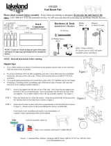
Please check contents before assembly. If any items are missing or damaged, do not take the unit back to
the store. Call 1-800-427-5136 for customer service and we will save you time by correcting any problems di-
rectly for you.
CF400/CF500 CEDAR LOG A-FRAME
A-FRAME COMPONENTS
1 - Top Rail
4 -Legs
6 - Braces
NOTE: Cracks or Checks in logs are part of the natural
beauty of cedar logs and should not be considered de-
fects.
A-FRAME HARDWARE
(Shown smaller than actual size)
2 - 8”
Bolts
2 - 1/2”
Nylock Nuts
2 - 3/8”
Nuts
2 - 1/2” x 6”
Eye Bolts
12 - 1/4” x 3”
Hex Washer
Head Screws*
4 - 1/2” Washers
* Lag Screws and
Washers may be
substituted for
Hex Washer
Head Screws
4 - 3/8” Washers
3/4” deep well
socket
9/16 deep well
socket
9/16” wrench
7/16” socket or
wrench
3/8” socket or
wrench
Power Drill
Tools that May Be Needed
Hammer
Tape Measure
Pencil
TIPS
A battery operated or electric drill will
make
assembly faster and easier.
Use a good quality penetrating oil or wood
deck sealer with a UV inhibitor & an anti-
fungal. (Make sure product is intended for
outdoor use.)
Read all instructions before
starting.
To start hex washer head screws, hammer into
wood about 1/2” then use wrench or socket to
tighten.
Do not completely tighten any screws until the
unit is fully assembled and setting on a level
surface.
If you have hardware left over after completing
your unit, it most likely has been assembled in-
correctly, and may not be safe to use. Please
call Customer Service at 1-800-427-5136, for
assistance.
Check all nuts and bolts for tightness before
and during each usage season.
NOTE:
Look for videos on:
https://www.youtube.com/watch?
v=Iqul3dHxNMo
https://www.youtube.com/watch?v=-OmqxSrmkYM

See figure 1A. Place a 1/2” washer
on the 6” eye bolt. Drive the eye
bolt through the hole in top rail, on
the opposite side from the counter
bore. Place 1/2” washer on the 6” eye
blot in the counter bore, then place
nylock nut on the eye bolt in the
counter bore. Tighten with 3/4”
socket. Repeat this process on the
other side. See figure 1B Lay top rail
on the ground with eye bolts down.
Lay top of legs parallel to top rail as
shown in figure 1B and attach all legs
with 8” bolts, 3/8” washers, and nuts,
using a washer on both ends of the
bolt. Repeat process on opposite side.
DO NOT TIGHTEN YET.
STEP 1
A-FRAME ASSEMBLY
figure 1A
1/2” NYLOCK NUT
1/2” WASHER
1/2” WASHER
6” EYE BOLT
3/8” NUT
3/8” WASHER
8” BOLT
3/8” WASHER
figure 1B
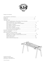
Pre-measure and mark rail and legs for
braces. Mark position of leg braces 32”
from the top of the legs as illustrated in
figure 2. Mark position of rail to leg brace
22 1/2” from the end of top rail and 24”
from the top of legs as shown in figure 2.
STEP 2
STEP 3
This will set your swing seat at
an average height from the
ground. If you wish to raise
the seat higher, attach leg
braces more than 32” from the
top of the legs. To lower the
seat height, attach them at a
point less than 32” from the
top of the legs.
(TWO PEOPLE RECOMMENDED.)
Lift top rail with legs attached allowing legs
to swing into position underneath. Attach
braces (as illustrated in figure 3) to pre-
marked positions tapping 3” hex washer head
screws with a hammer to start them into legs
and tightening them with a 7/16” wrench.
After all 6 braces are attached and frame is
setting on firm level surface, tighten them
securely. Now tighten the nuts and bolts that
attach the legs to the top rail with 9/16”
wrench, making sure bolts are TIGHT.
Factory: 1 Lakeland Place, Edmore, MI 48829, Phone: (800) 427-5136, Fax: (989) 427-5824
www.lakelandmills.com
Lakeland Mills recommends:
WeatherSeal Premium Oil-Based Exterior Wood Stain & Sealant
www.ContinentalProd.com
/