Page is loading ...

The Grace Machine Quilter
Assembly Steps:
Step 1: Attaching Legs to Frame Ends. . . . . . . . . . . . . . . . . . . . . . . . . . . . . . . . . . . . . . . .1
Step 2: Brace Assembly. . . . . . . . . . . . . . . . . . . . . . . . . . . . . . . . . . . . . . . . . . . . . . . . . . . .2
Step 3: Brace to End Assembly. . . . . . . . . . . . . . . . . . . . . . . . . . . . . . . . . . . . . . . . . . . . . 3
Step 4: Middle Leg Assembly . . . . . . . . . . . . . . . . . . . . . . . . . . . . . . . . . . . . . . . . . . . . . . 4
Step 5: Attaching the Middle Leg Assembly. . . . . . . . . . . . . . . . . . . . . . . . . . . . . . . . . . . .4
Step 6: Pole Mount End Hardware Install. . . . . . . . . . . . . . . . . . . . . . . . . . . . . . . . . . . . .5
Step 7: Pole Mount End to End Assembly. . . . . . . . . . . . . . . . . . . . . . . . . . . . . . . . . . . . 6
Step 8: Rail Assembly. . . . . . . . . . . . . . . . . . . . . . . . . . . . . . . . . . . . . . . . . . . . . . . . . . . . . 6
Step 9: Cog Wheel to Rail Assembly. . . . . . . . . . . . . . . . . . . . . . . . . . . . . . . . . . . . . . . . . 7
Step 10: Cog Stop Installation. . . . . . . . . . . . . . . . . . . . . . . . . . . . . . . . . . . . . . . . . . . . . . 8
Step 11: Frame Adjustment. . . . . . . . . . . . . . . . . . . . . . . . . . . . . . . . . . . . . . . . . . . . . . . . 9
Step 12: Right and Left Angled Leg Brace Assembly. . . . . . . . . . . . . . . . . . . . . . . . . .. . 9
Step 13: Table Top Assembly. . . . . . . . . . . . . . . . . . . . . . . . . . . . . . . . . . . . . . . . . . . . . 10
Step 14: Track Installation. . . . . . . . . . . . . . . . . . . . . . . . . . . . . . . . . . . . . . . . . . . . . . . . 11
Carriage Sub-Assemblies:
Sub Assembly 1: Wheels to Top and Bottom Plates. . . . . . . . . . . . . . . . . . . . . . . . . . . 12
Sub-Assembly 2: Left Handle Structure. . . . . . . . . . . . . . . . . . . . . . . . . . . . . . . . . . . . . 13
Sub-Assembly 3: Right Handle Structure. . . . . . . . . . . . . . . . . . . . . . . . . . . . . . . . . . . . 14
Sub-Assembly 4: Connecting the Handles. . . . . . . . . . . . . . . . . . . . . . . . . . . . . . . . . . . 15
Sub-Assembly 5: Attaching Platform and Bracket. . . . . . . . . . . . . . . . . . . . . . . . . . . . . 16
Sub-Assembly 6: Attaching Left Gear Linkage and Rear Lower Speed Control Lever. 17
Sub-Assembly 7: Attaching Right Gear Linkage. . . . . . . . . . . . . . . . . . . . . . . . . . . . . . . .18
Sub-Assembly 8: Attaching the Rear Upper Speed Control Lever. . . . . . . . . . . . . . . . . . 19
Sub-Assembly 9: Attaching the Lever Linkage. . . . . . . . . . . . . . . . . . . . . . . . . . . . . . . . .20
Sub-Assembly 10: Attaching the Front Speed Control Lever. . . . . . . . . . . . . . . . . . . . . 21
Sub-Assembly 11: Attaching the Pedal Clamp. . . . . . . . . . . . . . . . . . . . . . . . . . . . . . . . .23
Sub-Assembly 12: Assembling and Attaching the Stylus. . . . . . . . . . . . . . . . . . . . . . . . . . 24
Sub-Assembly 13: Attaching the Sewing Machine to the Top Plate . . . . . . . . . . . . . . . . 26
Sub-Assembly 14: Eyelet Assembly. . . . . . . . . . . . . . . . . . . . . . . . . . . . . . . . . . . . . . ... . . 26
Fabric Installation and Use of Frame:
Method #1: Hemming Your Fabric. . . . . . . . . . . . . . . . . . . . . . . . . . . . . . . . . . . . . . . . . . 27
Method #2: Cloth Leaders. . . . . . . . . . . . . . . . . . . . . . . . . . . . . . . . . . . . . . . . . . . . . . . . . .30
Placing the Top and Bottom Plates onto the Table. . . . . . . . . . . . . . . . . . . . . . . . . . . . . . 30
Rolling your fabric. . . . . . . . . . . . . . . . . . . . . . . . . . . . . . . . . . . . . . . . . . . . . . . . . . . . . . . . 31
The Four-Inch Principle. . . . . . . . . . . . . . . . . . . . . . . . . . . . . . . . . . . . . . . . . . . . . . . . . . . 31
EdgeMaster
TM
Assembly. . . . . . . . . . . . . . . . . . . . . . . . . . . . . . . . . . . . . . . . . . . . . . . . . . . 32
Carriage Stop Assembly. . . . . . . . . . . . . . . . . . . . . . . . . . . . . . . . . . . . . . . . . . . . . . . . . . . . 32
Turning Your Quilt Around. . . . . . . . . . . . . . . . . . . . . . . . . . . . . . . . . . . . . . . . . . . . . . . . .33
Optional Fourth Pole Assembly. . . . . . . . . . . . . . . . . . . . . . . . . . . . . . . . . . . . . . . . . . . . . . 34
Trouble Shooting Tips: . . . . . . . . . . . . . . . . . . . . . . . . . . . . . . . . . . . . . . . . . . . . . . . . . . . . 34
1
. . . . . . . . . . . . . . . . . . . . . . . . . . . . . . . . . . . . 36
. . . . . . . . . . . . . . . . . . . . . . . . . . . . . .36
Hand Quilting Configurations. . . . . . . . .
Sewing Machine Tips: . . . . . . . . . . . . . . . . .
Available A
. . . . . . . . . . . . . . . . . . . . . . . . . . . . . . . . . . . . . . 35
ccessories . . . . . . . . . . . . . .
atent Pending
opyright October 2002
m M. Bagley, GraceWood, Inc.
eproduction Prohibited)
P
C
Ji
(R

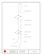
1-Left Frame End
1-Left Front
Leg
1-Left Back
Leg
Grace Machine Quilter
Parts List
1-Right Frame End
Inside View
1-Right Front
Leg
1-Right Back
Leg
4-Table Brace
1-Left Pole Mount End
1-Right Pole Mount End
1-Middle
Leg
1-Middle
Leg Brace
1-Right Angled
Leg Brace
2-Carriage
Stop
1-Left Angled
Leg Brace
1-Opposing
Middle Leg
2-Clamping
Bracket
2-Base
2-Clamping
Lever
2

3
1-Table Left Side
1-Table Right Side
1-Table Middle
Section
3-34" Rail
3-70" Rails
3-Square
End Cap
6-Leader Dowel
3-Coupler
3-Round
End Cap
3-Cog
Stop
1-60" Track
1-52" Track
3-Cog
Wheel
2-34" Track
2-20" Track

4
26-1/4" X 45mm Connector Bolt
8-1/4" X 35mm Connector Bolt
4-5/16" X 2" Hex Bolt
4-5/16" X 1 1/2" Hex Bolt
2-1/4" X 3/4" Hex Bolt
4- 5/16" X 2" Carriage Bolt
3-1/4" X 1 1/2" Truss Bolt
8-5/16" Flat
Washer
26-Rectangle
Nut Threaded
8-1/4" Flat
Washer
4-5/16"
Jamb Nut
4-Roller
Bushings
4-1 1/2" Fender
Washer
4-5/16"
Wing Nut
4-1/4"
Wing Nut
2-1/4" X 1 1/2" Carriage Bolt
2-Rectangle
Nut Unthreaded
1-4mm Alan
Wrench
Grace Machine Quilter Hardware
***Drawings display hardware in actual size***

5
Carriage Assembly Parts List
1-Bottom Plate
1-Top Plate
1-Left Main Handle
2-Lower
Rear Handle
1-Right Main Handle
1-Foot Pedal Plate
1-Lamp Holding Plate
1-Rear Lower
Speed Control
Lever
1-Left Gear
Linkage
1-Right Gear
Linkage
1-Rear Upper
Speed Control Lever
2-3/4"
Spacer
1-3/4"
Pocketed
Spacer
1-Front Speed
Control Lever
1-Lever
Linkage
1-Pedal
Clamp
2-Ball
Clamp
1-1/2"
Spacer
1-Ball
Swival
1-Pointer

6
Hardware for Carriage Assembly
8-1/4" X 1" Hex Bolt
1-1/4" X 70mm Connector Bolt
1-1/4" X 60mm Connector Bolt
5-1/4" X 50mm Connector Bolt
5-1/4" X 45mm Connector Bolt
2-1/4" X 40mm Connector Bolt
6-1/4" X 35mm Connector Bolt
2-1/4" X 3" Carriage Bolt
1-8mm X 25mm Bolt
3-1/4" Wing Nut
24-1/4" Nylock Nut
4-1/4" Square N
1-1/4" X 1 1/4"
2-1/4" Jamb Nu
6-5/16" Flat Washer
37-1/4" Flat Wash
2-Eyelet Screw
er
t
Thumb Screw
ut
8-Wheels

7
The Grace Machine Quilter
Instructions For Assembly & Use
Before You Begin
¾ Using the parts list as a reference, take the parts out of both boxes and make sure that you have them all. (If
there is something missing or broken, contact the Grace Company. We will promptly ship any needed item).
NOTE: The dowels are packaged inside the aluminum rails.
“This is a new product! We welcome your feedback on this product or these instructions. If you
encounter a problem during assembly or use of the Grace Machine Quilter, and you can’t seem to
overcome it, call us before frustration sets in! 1-800-264-0644.” --Grace
NOTE! Read each step all the way through before actually assembling parts in that step.
¾ Identify Hardware Packets:
--Main Hardware Packet (M)
--Carriage Assembly Hardware Packet (C)
¾ For ease in identifying bolts, keep the “C” packet sealed until
you work on the Carriage Sub-Assemblies.
¾
Because the connector bolts are so close in length, to assist in
distinguishing the different sizes, we recommend standing them on
end and grouping them according to length.
Tools Needed
¾
Alan Wrench
(Provided for use with all connector bolts)
¾ ½” Socket or Combination Wrench
¾ 7/16” Socket or Combination Wrench
Note: To help you distinguish wood parts, all end pieces are
marked with an “L” or “R” grooved into the wood on the
inside of the part.
Step 1: Attaching Legs to Frame Ends
Parts Needed: 1 – Left Front Leg 1 – Left Frame End
1 – Left Back Leg 1 - Right Frame End
1 – Right Front Leg 1 – Alan Wrench
1 – Right Back Leg
8 – ¼” x 35mm Connector Bolts (shortest)
¾ The Right Frame End will be connected to the outside of the
two right legs using two connector bolts each.
¾ Line up the front and back legs to the Right Frame End.
NOTE: be sure the “R’s” are all facing the same direction.
¾ Place the connector bolts through the holes from the outside
of the Frame End.
¾ Thread the bolts into the legs. The leg holes contain a metal
insert that will receive the threaded bolt.
¾ Using the Alan Wrench, tighten the Connector Bolts in all four bolts.
¾ Repeat this process for the Left Frame End.
Inside View
Right Side
Front of
Frame
Back of
Frame
35mm connector bolt
Left Assembly
Inside View
Front of
Frame
Back of
Frame
35mm connector bolt

Step 2: Brace Assembly
es
8
5/16 X 1 1/2 hex bolt
5/16 flat washe
r
Parts Needed: 4 – Brac
4 – 5/16” x 1 ½
5/16” Flat Washers
¾ he braces determines what size frame you will have. (Queen
N
t
N
¾ Put a washer onto the bolt. P brace and into the hole
of the second brace. The bolt wil e o
process for all four bolts.
tely
tighten the bolts at this time—
!
after installing the rails and
” Hex Bolt
4 –
Queen size
The manner in which you assemble t
size pictured above, Crib below).
the curved ends as pictured. The opposite end of
the (see
picture above).
ce. As you pair the braces
together, be sure the inserted T-Nuts are visible,
r
uts to ull ou using
ome a rt.
T-nut on the Outside
¾ To join, place the braces together overlapping
brace has a key that should always face up
OTE! There is a metal T-nut already inserted in
he end of each bra
facing toward the outside (away from the othe
brace—see right)! Failure to do so may force the T-
p t of the brace, ca the braces to
c pa
ut the bolt with washer through the slot of one
l com ut through the T-Nut on the opposite end. Repeat this
¾ NOTE! Do not comple
ze
FINGER TIGHTEN ONLY
You will completely tighten them
adjusting your frame (Step 11).
Crib Si
5/16 X 1 1/2 hex bolt
5/16 flat washer
Key

S
45mm connector
bolt
fitting the keyed end of the brace into the
tep 3: Brace to End Assembly
Assembly
ssembly
Br
– ¼” (longer)
4 – Rectangle Nuts
1 – Alan Wrench
¾ Connect the brace to the Left and Right Ends by
slots of the Frame Ends. Line up the Frame End holes with the opening in the brace. (Remember to
keep the brace’s keyed end up).
¾ Push a connector bolt through the Frame End hole and into the open slot of the brace.
¾ Thread a rectangle nut onto the end of the
bolt, so that it rests in the cross portion of the
slot (see close-up below right).
connector bolt, holding the nut in place.
¾ Repeat this process to connect the
remaining three brace ends.
Parts Needed: Left Frame End
Right Frame End A
Two ace Assemblies
4 x 45mm Connector Bolts
¾ Using an Alan Wrench tighten the
Key
rectangle
nut
45mm connector
bolt
Cross Portion
of slot
Right Side
45mm connector
bolt
9

Step 4: Middle Leg Assembly
Parts Needed: 1 – Middle Leg
1 – Opposing Middle Leg
r Bolts
2 – Rectangle Nuts
ench
Connect the Center Legs by placing the connector bolts through each leg hole as pictured, and into
the Center Brace. (There is no specific front or back Leg, but the two legs are slightly different based on
the position of the hole in the “I” slot).
¾ Thread a rectangle nut onto the ends of the bolts.
¾ Holding the nuts in the cross portion of the slot, tighten
the conne bol
Step 5: Attaching the Middle Leg Assembly
1 – Middle Leg Brace
2 – ¼” x 45mm Connecto
1 – Alan Wr
¾
NOTE: If the Center Brace is placed backward between the
two legs, the holes will not line up properly.
Middle Legs
& Brace
10
Queen Size
5/16 X 2
hex bolt
5/16 flat
washer
ctor ts using the Alan Wrench.
Parts Needed: 1 – Middle Leg Assembly
4
4 – 5/16” Flat washers
¾ With the em to the
Brace/End Assembly. First
1 – Brace/End Assembly
– 5/16” x 2” Hex Head Bolt
se pieces assembled, attach th
putting the Middle Legs
sideways inside the braces (see illustration top of next page).
¾ Second, put 5/16” flat washers on each of four hex head
bolts. Put those bolts through the two queen size or crib size slots on both sides of the Brace Assembly
and into the two holes at the tops of the Center Legs.
¾ These bolts will go into the inserted T-Nuts of the
Middle Legs.
¾ NOTE! Leave these loose by ONLY FINGER
TIGHTENING them at this time. You will tighten
them after the rails are installed into the frame (Step 11).
rectangle
nut
45mm
connector
bolt
T-nuts
5/16 X 2
hex bolt
5/16 flat
washer
Crib Size

Step 6: Pole Mount End Hardware Install
ount 1 – Left Pole Mount
lts 4 – Roller Bushings
4 – 5/16” Jamb Nuts
¾ The Pole Mount Ends are designed to be adjustable both for height and front to back positioning.
¾ As you install two carriage bolts into each of the Left and Right ends, keep in mind the following:
1. Be sure the bolts are put through th
of the part.
tightened. The roller
bushings will fit loosely on
the bolt.
Parts Needed: 1 – Right Pole M
4 – 5/16” x 2” Carriage Bo
4 – 1/4” Flat Washers
Left Pole Mount End
Insid
arriage bolt
5/16 jamb
nut
roller
bushing
e Pole Mount Ends so the heads show on the inside
2. Each carriage bolt can be placed in one of seven
matching
holes. (i.e. If the front bolt
placed in hole #1, the back bolt must also be placed in ho
is
le #1).
sitioning is achieved by placing the two carriage
in the center (#4) holes (each in the hole fourth from the front). This is based on a
machine with a throat length of about 7 inches.
t to reposition the rails by placing the bolts in
the throat of the machine, the closer the bolts should be
to the front (holes #1, #2 etc.)
5. The jamb nuts should be
completely tightened with a
wrench.
6. The nylon roller bushings
should be placed on the
bolts after the jamb nuts are
Right Pole Mount End
5/16 X 2
carriage bolt
1/4 flat
washer
5/16 jamb
nut
roller
bushing
1
2
4
3
5
6
7
3. A good average setting for front-to-back rail po
bolts
4. Depending upon the machine you may later wan
different holes. A good rule of thumb is the bigger
e view
5/16 X 2
c
1/4 flat
washer
6
7
1
2
3
4
5
1
2
3
4
5
6
7
7
6
5
4
3
2
1
11
Inside View

Step 7: Pole Mount End to Frame End Assembly
4 – 1½” Fender Washers
4 – 5/16” Wing Nuts
Now you are ready to attach the Pole
Mount Ends to the rest of the End Assembly.
First, position the Pole Mount Ends in the
inside of the End Assembly.
End
carriage bol
¾ Place a fender washer and wing nut on
each bolt.
¾ As you tighten, make sure the part is level
by looking at the bottom of the Pole Mount
End and the grooved lines on the inside of the
Frame End Piece. (A good estimated setting is
to line up the bottom of the Pole Mount End
on the 3
rd
line up on the set of lines closest to
the table tops. However , you will readjust this
to your machine later).
¾ Complete this step for both sides.
¾
¾ Holding the outer side of the Pole Mount
to the slots of the End Piece, fit the two
ts through the slots.
Step 8: Rail Assembly
3 or 4* – 70” (Longer) Rails
3 or 4* – 34” (Shorter) Rails w/ coupler
Parts Needed:
¾ If you are setting up your frame in Crib Size, you will be
ssembly:
For Queen Size, these parts are also required:
5/ g
*Needed with Optional Fourth Pole
using the Long 70” Aluminum Rails by themselves. The Queen
Size set-up requires the following a
¾ Construct your queen size rails by connecting the long and
short aluminum rails using the aluminum connectors.
cap
cog
wheel
Inside View
16 win
nut
round end
cap
34 inch
rail
Queen Size
coupler
70 inch
rail
square end
Left End Assembly
fender washer
Right End Assembly
Inside View
fender
washer
5/16 wing
nut
12

Step 9: R
arts Needed: 3 or 4* Round End Caps
3 – Ratchet Wheels
with the ratchet wheel. The round end cap goes on the left side (opposite the ratchet wheel). Line up
the smaller end of the cap so the grooves match those
rts Needed: 3 or 4* Round End Caps
3 – Ratchet Wheels
with the ratchet wheel. The round end cap goes on the left side (opposite the ratchet wheel). Line up
the smaller end of the cap so the grooves match those
atchet Wheel to Rail Assembly
P
3 or 4* Square End Caps 3 or 4* Square End Caps
*Needed with Optional Fourth Pole
*Needed with Optional Fourth Pole
¾ Complete the rail by adding a rail cap on each end. The¾ Complete the rail by adding a rail cap on each end. The square end cap goes on the right end along
on the rail and push the cap into the rail until it is
set in place.
ight at first. It may help on this first assembly, to put the end
g the end of the rail onto a carpeted floor a couple of
while the ratchet wheel on the middle rail is
the opposite.
To be sure about tooth d
i
square end cap goes on the right end along
on the rail and push the cap into the rail until it is
set in place.
ight at first. It may help on this first assembly, to put the end
g the end of the rail onto a carpeted floor a couple of
while the ratchet wheel on the middle rail is
the opposite.
To be sure about tooth d
i
¾ NOTE: The end caps may be a little t
caps in place and completely seat them by drivin
times.
¾ NOTE: The end caps may be a little t
caps in place and completely seat them by drivin
times.
Crib Size
l70 inch rai
ca
Now add the black ratchet wheel over th
wheel goes on the optional Fourth Pole assemb
nubs on the square end caps.
NOTE! Pay close attention to the toot
ection:
Now add the black ratchet wheel over th
wheel goes on the optional Fourth Pole assemb
nubs on the square end caps.
NOTE! Pay close attention to the toot
ection:
¾ e square pole cap on the right end of each rail (no ratchet
ly). Line up the notches on the Ratchet Wheel with the
h
dir
1. The ratchet wheel teeth on the two outside
frame,
¾ e square pole cap on the right end of each rail (no ratchet
ly). Line up the notches on the Ratchet Wheel with the
h
dir
1. The ratchet wheel teeth on the two outside
frame,
round end
p
square end
ca
p
cog wheel
rails face toward the table side of therails face toward the table side of the
2.
¾
2.
¾
irection, you
tchet stop once it is
llustration bottom of
Now put the rails into the frame. This
le
irection, you
tchet stop once it is
llustration bottom of
Now put the rails into the frame. This
le
can double check the fit of the ratchet can double check the fit of the ratchet
wheel with its ra
assembled (see
wheel with its ra
assembled (see
next page). next page).
illustration shows the frame from the tab
side, right end. The rails will simply slide
into place as you put them into the proper
grooves.
illustration shows the frame from the tab
side, right end. The rails will simply slide
into place as you put them into the proper
grooves.
¾ See diagram on page 33 for placement
of the fourth pole into the frame.
¾ See diagram on page 33 for placement
of the fourth pole into the frame.
13
Right Frame End Assembly

Step 10: Ratchet Stop Installation
bolts, or else
they will
puncture the
wood!
FINGER
TIGHTEN
ONLY!!
Parts Needed: 3 – Ratchet Stops
3 – ¼” x 1 ½” Truss Bolts
NOTE! Do not
over-tighten the
e of Frame
2
¾ Install the three ratchet stops to Right Pole Mount End by putting a ¼” x 1 ½” Truss Bolt through
the hole in each ratchet stop, and into the metal insert as pictured.
Right Sid
cog stop
1/4 X1 1/
truss bolt
14

Step 1
¾ With the rails now in place it is time to adjust the frame to the rails.
work
ere is no
end of the rail and the End Piece.
snuggly with no gaps into the end pieces.
be able to roll freely.
NOTE! As you tighten the bolts connecting the braces, be sure the brace pieces a
with each other so that there is no sagging. You may eye sight along the top edge
straightness.
¾ Also tighten the bolts that attach the Center Leg support assembly, making sure they are properly set
to hold up the table.
1: Frame Adjustment
This adjustment will only
gap between the
They should still
re aligned
to confirm
¾ NOTE! Be aware that as you apply the table tops (in step 13), it may be necessary to
readjust the braces so that holes line up.
Step 12: Right and Left Angled Leg Brace Assembly
if you have left the bolts loose that connect the Braces and Center Legs. If they are tight, you
must loosen them at this point.
¾ Standing at the Left End of the frame, push the frame all the way in so th
¾ Check each rail to make sure they fit
Parts Needed: 1 – Right and Left Angled Leg Brace
2 – ¼” x 45 mm Connector Bolt
2 – Rectangle Nuts
1 – Alan Wrench
¾ Connect the right and left Angled
Brace to the Front Legs of the frame
by putting a 45mm connector bolt
through the front leg and into the slot
in the Angled Brace.
¾ Put a rectangle nut in the cross slot
in the brace and thread the bolt
through it.
¾ Tighten the connector bolt using
the Alan wrench.
¾ You
will attach
angle
brace to the
table top in
the next
step.
the top of
the
note letter
15
Left Side of Frame
Inside View
rectangle nut
45mm
Connector
bolt
Left Side of Frame
Inside View
note letter
rectangle nut
45mm
connector
bolt

Step 13: Table Top Assembly
Parts Needed: 1 – Table Left Side
1 –Table Middle Section
1 –Table Right Side
18 – ¼” x 45mm Connector Bolts
18 – Rectangle Nuts
1 – Alan Wrench
¾ For queen size assembly, all
three Table Sections will be used.
For crib size, the center Table Leaf
will be omitted.
¾ The Left Side is the one
with the slots. The Right Side
has circular holes.
e table side of
t
ht
Side at the right of the frame.
s to
the Brace Assembly using 45 mm
c
¾ Standing at th
he frame, lay these pieces onto the
Brace Assembly as pictured,
beginning with the Table Rig
¾ Connect the Table section
onnector bolts and rectangle nuts.
¾ Completely tighten
each connector bolt using
the Alan wrench.
¾ Referring to the
illustration on the left, be
sure you put a connector
bolt through each hole
on the Table Tops.
Queen size
45mm connector
rectangle nut
Crib Size
bolt
16

Leg/Table Support Assembly
¾ Now connect the Table Tops to the Front Leg Support
installed in Step10.
¾ Line up the top of the support brace with its corresponding
hole in the Left and Right Table Sides.
¾ Insert a 45 mm connector bolt and rectangle nut and
completely tighten using an Alan wrench.
Step 14: Track Installation
you
45mm connector
bolt
rectangle nut
Parts Needed: 1 –60” Track
1 –52” Track
the top and bottom grooves.
left, as pictured above.
t thr
on-thr
slightly bigger hole (they should be the only two left!
¾ flat
head so that it sits flush against the edge of the trac
2 –20” Track
*2 –34” Track
2 –1/4” x ¾” Hex
Head Bolts
2 – ¼” Flat washer
2 –Unthreaded
Rectangle Nuts
2 –1/4” Wing Nuts
*queen size only
¾ Start on the right side and place the
52” Track into the top track groove
(closest to the rails).
¾ Place the 60” Track into the bottom track groove and slide it all the way to the right.
, next insert one 34” track into
slide hem a
For both crib and queen size assembl
the top and bottom grooves and
y, place a 20” Track into
Place these pieces to the furthest
You will secure these tracks in place by placing a ¾” hex head
Left Angled
Leg Support
Brace
Crib size
52 inch
track
60 inch
track
20 inch
track
¾ If you are doing the queen size assembly
lace. t gainst the tracks in p
¾
¾
bol ough a non-threaded rectangle nut and then through the
hole at the left side of the Left Table Top.
NOTE! The
eaded
rectangle nuts have a
edge of the bolt
k.
Left Side of Frame
1/4 X 3/4
hex bolt
unthreaded
rectangle nut
1/4 flat
washer
1/4 wing
bolt
Outside View
¾
n
Once through the hole, line up the
17

¾ Pla
apply pressure to the tracks to remove any play of gaps.
Note: You have now completed the frame portion of your Grace Machine Quilter. If you
assembled your frame in the crib size, do not be concerned that you have extra hardware. Keep
these in the baggy and save them for future use
ce a ¼” flat washer and ¼” wing nut onto the end of the bolt. Before tightening the wing nut,
¾
.
¾ Before proceeding, take the hardware packet marked “C” and remove the hardware. We
recommend that you stand up all the flat-head connector bolts in line and put them in order of size. This
will help you distinguish them as you move through each step, as many sizes are very similar.
Carriage Sub-Assemblies
Sub Assembly 1: Wheels to Top and Bottom Plates
Parts Needed: 1 – Top Plate
1 – Bottom Plate
8 – Wheels
¾ NOTE! The bolts and w
the platform.
¾ First, turn the Top and B
plate has four places for wheels to be installed.
¾ The hardware arked with an “C”.
e is a bolt wall and a washer wall surrounding this
slot. Using the diagram as a guide, place a hex head bolt into the hole on the bolt side of the slot.
¾ gh the hole, through the wheel, and through the hole on the opposite wall.
¾ Place a washer on the end of the bolt. At this point
place, lining
nce d k nut onto the end of the bolt and tighten it completely.
¾ Repeat this process for the other seven roller bearings. After each one is installed turn it to make
sure it rotates with no problems.
8 – ¼” x 1” Hex Bolt
8 – ¼” x Flat washers
8 – Nylon Lock Nut
heels may be a tight fit going into
ottom Plates upside down. Each
for this step is found in the separate hardware packet
To install a wheel you need a ¼” x 1” hex head bolt, a ¼” flat washer and a nylon lock nut.
ere the wheel will sit. Ther
Close Up of Wheel Assembl
y
m
¾
¾ Identify the slots wh
Push the bolt throu
you need to turn the bolt head so it slips into
1/4 X 1
hex bolt
washer
1/4 nylock
nut
up flush with the shape of the wall.
¾ O one, place a nylon loc
Bottom Plate
wheel
1/4 flat
wheel
1/4 X 1
hex bolt
1/4 flat
washer
1/4 nylock
nut
Top Plate
wheel
1/4 flat
washer
1/4 nylock
nut
1/4 X 1
hex bolt
18

Sub-Assembly 2: Left Handle Structure
ts N
1 – Left Main Handle
¾ or bolts, put them on threads first, nylon last.
Hold the head of the bolt stationary with the Alan Wrench while turning the nylock with the Socket
Wre
Par eeded: 1 – Top Plate
1 – Lower Rear Handle
2 – ¼” x 50mm Connector Bolt
2 – ¼” Flat washers
2 – ¼” Nylock Nut
¾ Pair the Left Main Handle and L
on the outside, line up the holes at the bottom and pl
¾ Insert 50mm connector bolts in
¾ Place a ¼” flat washer and ¼” nylock nut on each bolt.
¾ Completely tighten the nylocks
ower Rear Handle together as pictured. With the Left Main Handle
ace them inside the walls of the Top Plate.
to the inside wall, through the handles and out the other wall.
on both bolts.
NOTE: When tightening nylocks onto these connect
nch.
Left Handle Structure
Left Main
Handle
Handle
1/4 nylock
50mm connector
Lower Rear
1/4 fl
wash
at
er
bolt
nut
19

b-Assembly 3: Right Handle Structure Su
arts Need
¾
¾
¾
¾
P ed: 1 – Right Main Handle
2 – ¼” x 50mm Connector Bolt
2 – ¼” Flat washers
2 – ¼” Nylock Nut
Pair the Right Main Handle and Lower Rear Handle together as pictured. With the Right Main
Handle on the outside, line up the holes at the bottom and place the inside the walls of the Top Plate.
Insert 50mm connector bolts into the inside wall, through the handles and out the other wall.
Place a ¼” flat washer and ¼” nylock nut on each bolt.
Completely tighten the nylocks on both bolts.
Right Handle Structure
1 – Rear Lower Handle
Handle
bolt
50mm connector
1/4 flat
washer
1/4 nylock
nut
Right Main
Lower Rear
Handle
20
/