Page is loading ...

Pg.1
The Quilters D-Lite
Professional Quilters Kit Frame
Assembly Instructions
Table of Contents:
Before you begin . . . . . . . . . . . . . . . . . . . . . . . . .
Wood parts . . . . . . . . . . . . . . . . . . . . . . . . . . . . .
Hardware . . . . . . . . . . . . . . . . . . . . . . . . . . . . . .
Step 1 - Middle leg - Assembly . . . . . . . . . . . . . . .
Step 2 - Height adjustable legs . . . . . . . . . . . . . . .
Step 3 - Adjustable legs to middle section . . . . . . .
Step 4 - Middle legs - Table brace . . . . . . . . . . . . .
Step 5 - Middle legs - Conduit bracket . . . . . . . . . . .
Step 6 - Middle legs - Conduit clamps . . . . . . . . . . .
Step 7 - Frame ends - Carriage bolts . . . . . . . . . . .
Step 8 - Frame end - Height adjustable legs . . . . . .
Step 9 - Frame end - Rail brackets . . . . . . . . . . . . .
Step 10 - Frame end - Conduit braces . . . . . . . . . . .
Step 11 - Frame end - Conduit clamps . . . . . . . . . .
Step 12 - Table track . . . . . . . . . . . . . . . . . . . . . .
Step 13 - Fabric rail . . . . . . . . . . . . . . . . . . . . . . .
Step 14 - Bottom plate wheels . . . . . . . . . . . . . . . .
Step 15 - Bottom plate tracks A . . . . . . . . . . . . . . .
Step 16 - Bottom plate tracks B . . . . . . . . . . . . . . .
Step 17 - Top plate wheels . . . . . . . . . . . . . . . . . .
Step 18 - Top plate handles . . . . . . . . . . . . . . . . . .
Step 19 - Top plate braces . . . . . . . . . . . . . . . . . .
Step 20 - Levers to top plate . . . . . . . . . . . . . . . . .
Step 21 - Lever linkage . . . . . . . . . . . . . . . . . . . .
Step 22 - Pedal clamp . . . . . . . . . . . . . . . . . . . . . .
Step 23 - Stylus clamp . . . . . . . . . . . . . . . . . . . . .
Fabric installation . . . . . . . . . . . . . . . . . . . . . . . . .
Making leader cloths . . . . . . . . . . . . . . . . . . . . . . .
Leader cloth installation instructions . . . . . . . . . . . .
Installing fabric onto rails . . . . . . . . . . . . . . . . . . .
Step 1 - Quilt backing to 2nd rail . . . . . . . . . . . . . .
Step 2 - Quilt top to 3rd rail . . . . . . . . . . . . . . . . . .
Step 3 - Batting . . . . . . . . . . . . . . . . . . . . . . . . . .
Step 4 - Attaching quilt fabric to take up rail . . . . . .
Step 5 - Placing sewing machine onto frame . . . . . .
Rolling quilt fabric . . . . . . . . . . . . . . . . . . . . . . . . .
Pg. 2
Pg. 3-4
Pg. 5
Pg. 6
Pg. 7
Pg. 7
Pg. 8
Pg. 8
Pg. 9
Pg. 9
Pg. 10
Pg. 10
Pg. 11
Pg. 11
Pg. 12
Pg. 13
Pg. 14
Pg. 15
Pg. 15
Pg. 16
Pg. 16
Pg. 16
Pg. 17
Pg. 18
Pg. 18
Pg. 20
Pg. 21
Pg. 21
Pg. 22
Pg. 22
Pg. 22
Pg. 23
Pg. 23
Pg. 23
Pg. 24
Pg. 24

Pg.2
Before you Begin:
Before you can put the Quilters D-Lite together you need to purchase 6 to 7 pieces of 1-1/4”
conduit, which will be used for holding the quilt fabric, as well as for the quilting frame table, and
track.
The Quilters D-Lite frame is designed to be used with a broad range of different sewing machines.
You should be able to easily use just about any sewing machine on this quilting frame. There are
two ways to build the quilting frame. This instruction manual will focus on the recommended setup,
but will mention the required steps to assemble the frame in the other conguration. The frame
congurations are as follows: Standard conguration (Recommended), and Heavy Duty
conguration, for sewing machines weighing more than 100 pounds.
If you are building the Standard conguration, you will need to purchase 6 lengths of conduit.
Plan on spending around $15 per piece of conduit, or around $100 total. If you have a sewing
machine that weighs 100 pounds, or if you feel that your quilting frame requires additional support,
then you will need to purchase 7 lengths of conduit, which should cost around $125.
The Standard Conguration, uses 2 conduit tracks, and works great with sewing machines
weighing up to 100 pounds. If your sewing machine weighs less than 100 pounds, build your frame
this way. Building the standard conguration will save you from having to purchase 1 additional
piece of conduit. The sewing machine carriage will also move more smoothly on the frame, since
the additional piece of conduit used in the heavy duty conguration adds friction, which will affect
carriage movement.
You can make your quilting frame any size that you want, but 10 feet is an ideal size because a
standard length of conduit is 10 feet long. Whatever length you decide to make your frame, please
carefully measure each piece of conduit and make sure that no piece varies in length more than
1/16”.
You can nd the conduit that you need in just about any hardware store (Lowes, Home Depot, etc.).
Again, you need to get 1-1/4” Steel conduit. Most likely you will nd conduit that is specied as
EMT. 1-1/4” EMT conduit is great for this project, but there are also other kinds of steel conduit that
will work just as well. Just make sure that the conduit outside diameter is 1-1/2” (1-1/4” conduit is
1-1/2” outside diameter), and that the conduit caps that were supplied with your frame kit t into the
conduit.
When you are looking for conduit, nd conduit that is as straight and smooth as possible.
You will also need a way to attach your quilt fabric to the (conduit) fabric rails. The Grace Company
highly recommends using the Start Right leader cloths, available for purchase direct from The
Grace Company, or ask if your Grace Company products dealer carries them. The Start Right leader
cloths include pre cut, hemmed, and marked fabric. Velcro is also provided for quick attachment, and
removal of the leader cloths.
There are also other Commercially available leader cloths.
You may also make your own leader cloths (Instructions on pg. 22). If you make your own leader
cloths you will need to purchase fabric, and a way to attach the fabric to the rails. See pg. 22 for
recommendations.

Pg.3
A- Middle Leg (2)
C- Middle Leg
Brace (1)
D- Middle Height
Adjustable Leg (2)
B- “T”
Bracket (2)
E- Table Brace
(5)
F- Leg Brace (8)
G- Left Frame
End (1)
H- Right Frame
End (1)
I- Conduit
Clamp (10)
J- Height
Adjustable
Leg “A” (2)
K- Height
Adjustable
Leg “B” (2)
L- Left
Take-Up Rail
Bracket (1)
M- Right
Take-Up Rail
Bracket (1)
N- Left Fabric
Layers Rail
Bracket (1)
O- Right Fabric
Layers Rail
Bracket (1)
Wood Parts 1

Pg.4
P- Left Handle
(1)
Q- Top Plate (1)
R- Right Handle
(1)
S1- Thin - Cross
Brace (1)
S2- Cross
Brace (1)
T- Front Top
Plate Brace
(1)
U- Bottom
Plate End (2)
V- Bottom
Plate (1)
Y1- Right Back
Lever(1)
W- Front
Lever (1)
AA- Back Lever
Linkage (1)
X- Middle
Lever (1)
Y2- Left Back
Lever (1)
Z- Front Lever
Linkage (1)
CC- Pedal
Clamp (1)
BB- Pedal Clamp
Wheel (1)
DD- Pedal Clamp
Spacer (3)
EE- Stylus
Base (1)
FF- Stylus
Clamp (1)
GG- Stylus
Mount (1)
Wood Parts 2

Pg.5
(12) M6 X 60mm
Connector Bolt
(10) M6 X 50mm
Connector Bolt
(14) M6 X 45mm
Connector Bolt
(21) M6 X 30mm
Connector Bolt
(12) M8 X 75mm
Carriage Bolt
(10) M8 X 50mm
Carriage Bolt
(8) M8 X 70mm
Hex Bolt
(6) M8 X 30mm
Hex B olt
(4) M6
Cap Nut
(28) Knob
(32) Fender
Washer
(39) M8 Jam
Nut
(20) M6
Square Nut
(8) M6 Nylock
Nut
(24) 12mm
Wood Screw
(6) M8
Cap Nut
(1) Open End Wrench
10mm, and 13mm
(2) 4mm Allen
Wrench
(1) 5mm Allen
Wrench
(31) M8 Washer
(15) M6 Washer
(6) Saddle Foot
(6) Adjustable
Foot
(42) Rail
End Cap
(14) Bolt
Cone
(5) Rail
Spacer
(4) 3/8” Fender
Washer
(4) 1/4”
Cap Nut
(3) Truss Bolt
(13) 1/4”
Square Nut
Additional Hardware Pack
Bagged in Box 2 of 2
Wrapped in paper in
Box 2 of 2
(3) Ratchet
Stop
(3) Ratchet
Wheel
Hardware

Pg.6
Step 1: Middle leg - Assembly
Parts needed:
2) M8 X 50mm carriage bolt
2) M8 X 65mm carriage bolt
2) M6 X 60mm connector bolt
4) M8 washer
4) M8 jam nut
2) M6 square nut
2) A- Middle leg
2) B- Middle leg “T” bracket
1) C- Middle leg brace
M8 X 65mm carriage bolt
M8 X 50mm carriage bolt
M8 washer
M8 jam nut
M6 X 60mm connector bolt
Middle leg “T” bracket
Middle leg
Fig. 1-1
M6 square nut
middle leg brace
Fig. 1-2
Step 1-3: Insert a square nut into each of the “T” slots in the ends of the middle leg brace, as
shown in Fig. 1-2.
Step 1-4: Secure both middle legs to the middle leg brace. Tighten the M6 X 60mm connector
bolts in the middle legs securely into the M6 square nuts.
Note: Be sure that you have the notches in each end of the middle leg brace facing the same way
as they are in the illustration. The notches allow the middle leg brace to clear the heads of the M8 X
65mm carriage bolts that are located in the middle leg “T” bracket.
Step 1-1: Assemble the middle legs as shown in Fig. 1-1. (Build 2)
Note: The M6 X 60mm connector bolt is not secured in place (in this step), but should be in place to
assist in lining up the middle leg “T” bracket correctly.
Step 1-2: Line up the “T” bracket as squarely as possible. The connector bolts will be fastened in
step 1-2.
notches

Pg.7
Height adjustable leg
fender washer
plastic knob
Step 2 - Height adjustable legs
Parts needed:
6) Leveling foot
6) Leveling foot saddle
24) 12mm wood screw
2) D- Middle height adjustable legs
2) J- “A” Height adjustable legs
2) K- “B” Height adjustable legs
Fig. 2-1
Step 2-1: Attach a leveling foot saddle to the end of each height adjustable leg using (4) four
12mm wood screws, as shown in Fig. 2-1.
Step 2-2: Screw a leveling foot into each leveling foot saddle. The middle height adjustable legs
will be used in step 3, and the “A”, and “B” height adjustable legs will be used in step 8.
Step 3-1: Place a middle height adjustable leg assembly onto
the exposed ends of the bolts on each side of the middle leg
assembly, as shown in Fig. 3-2.
Step 3 - Adjustable legs to middle section
Parts needed:
4) plastic knob
4) fender washer
1) Middle leg - Assembly
2) Middle height adjustable leg - Assembly
Fig. 3-2
12mm wood screw
Leveling foot
Leveling foot saddle
notched side
Note: place the notched side of
the middle height adjustable leg
against the middle leg assembly.
Step 3-2: Secure the height adjustable legs to the middle leg assembly by rst placing a fender
washer onto the exposed end of each bolt, and then tightly fasten a plastic knob onto each bolt.
Note: Attach both middle legs so that they are the same height.
Fig. 3-1

Pg.8
Step 4 - Middle legs - table brace
Parts needed:
Hardware:
2) M6 X 60mm connector bolt
2) M6 square nut
1) E- Table brace
2) I- Conduit clamp
1) Middle leg - Assembly
M6 X 60mm connector bolt
table brace
M6 square nut
conduit clamp
Fig. 4-1
Step 4-1: Insert a M6 square nut into the “T” slots in each end of the table brace.
Step 4-2: Place the table brace into the notches at the ends of each of the middle legs, as shown in
Fig. 4-1.
Step 4-3: Now, insert a M6 X 60mm connector bolt through the hole in each conduit clamp.
Step 4-4: Finally, insert one of the M6 X 60mm connector bolts through each of the holes in the end
of each middle leg, and nger tighten into the square nut.
Step 5 - Middle legs - conduit braces
Parts needed:
4) M6 X 30mm connector bolt
4) M6 cap nut
4) F- Conduit brace
1) Middle leg - Assembly
slot
M6 cap nut
M6 X 30 connector bolt
Fig. 5-1
conduit brace
Step 5-1: Attach the conduit braces to the middle leg
assembly by inserting a M6 X 30mm connector bolt through
one of the holes in either end of each conduit brace.
Step 5-2: Insert a M6 cap nut through each of the outer
holes in the middle leg “T” bracket.
Step 5-3: Fasten the M6 X 30mm bolt into the cap nut
using the included 4mm allen wrenches.
Note: When placing the conduit brace onto the assembly make sure that the slots on each end of
the brace, face toward the inside of the middle leg Assembly.

Pg.9
Step 6 - Middle legs - conduit clamps
Parts needed:
4) M6 X 60mm connector bolt
4) square nut
4) I- Conduit clamp
2) E- Table brace
1) Middle leg - Assembly
Step 6-1: Insert a square nut into the “T” slots in each end of the table braces.
Step 6-2: Place a table brace into the notches at the ends of each of the conduit braces.
Step 6-3: Now, insert a M6 X 60mm connector bolt through the hole in each conduit clamp.
Step 6-4: Finally, insert each M6 X 60mm connector bolt through the hole in the end of each
conduit brace, and nger tighten into the square nut.
Conduit clamp
Table brace
M6 X 60 connector bolt
square nut
Fig. 6-1
narrow end
M8 jam nut
M8 washer
M8 X 50 carriage bolt
Step 7 - Frame ends - carriage bolts
Parts needed:
16) M8 X 50mm carriage bolt
16) M8 Hex bolt
16) M8 washer
1) G- Left frame end
1) H- Right frame end
Build the left and right frame ends.
Step 7-1: Insert a M8 X 50mm carriage bolt through
each location shown in Fig. 7-1.
Step 7-2: Fasten the carriage bolts to the frame ends
using a M8 washer, and M8 jam nut on each bolt.
Note: Tighten the M8 jam nuts completely, so that the
head of each carriage bolt sits at against the surface of
the wood.
Fig. 7-1
Note: Make sure that the narrower ends
of all of the table braces are towards the
same end of the assembly when installed,
as shown in Fig. 6-1.
Left frame end
bolt locations
Note: The head of the bolt should be on the side of the frame end that has notches cut in it. (See
Fig. 10-1)

Pg.10
adjustable
leg “A”
adjustable
leg “B”
plastic knob
fender washer
Step 8 - Frame end - height adjustable legs
Parts needed:
8) plastic knob
8) fender washer
2) Frame end - Left and right Assemblies
2) “A” Height adjustable legs - Assembly
2) “B” Height adjustable legs - Assembly
Step 8-1: Attach a height adjustable leg to each side of the
frame ends as shown in Fig. 9-1. (Do this exactly the same way
as you did in step 3.
Note: When you place the height adjustable leg onto the frame
end, make sure that the notch at the top of the height adjust-
able leg is toward the middle of the frame end.
Note: The height adjustable legs will be placed opposite to how
they are shown, on the right frame end (not shown). Make sure
that all legs are adjusted to the same height.
Fig. 8-1
Fabric layers
rail bracket
fender washer
plastic knob
Step 9 - Frame end - Rail brackets
Parts needed:
4) plastic knob
4) fender washer
1) L- Left take-up rail bracket
1) M- Right take-up rail bracket
1) N- Left fabric layers rail bracket
1) O- Right fabric layers rail bracket
2) Frame end - Assembly
Take-up rail
bracket
Step 9-1: Attach the rail brackets to each of the
frame ends as shown in Fig. 9-1.
Note: When you place a rail bracket onto the frame
end, make sure that the side of the brackets with the
lines cut into it goes against the frame end. There
is a left and right version of each rail bracket, and
each bracket will only work in one location. (Notice
the location of the indicated notches at the top of the
take-up rail brackets.)
Fig. 9-1
notch
left frame end

Pg.11
Step 10 - Frame end - Conduit braces
Parts needed:
4) M6 X 45 connector bolt
4) square nut
4) F- Conduit brace
2) Frame end - Assembly
Step 10-1: Insert a square nut into the “T” slot in
one end of each of the conduit braces. Fig. 10-1.
Step 10-2: Attach the conduit braces to the frame
ends by inserting a M6 X 45mm connector bolt
through the hole on the outer side of the frame
ends for each conduit brace.
Step 10-3: Thread the connector bolts into the
square nuts located in the conduit braces, as shown
in Fig. 10-2.
Note: The conduit braces go into the outer
notches in the frame ends.
Note: Make sure that you attach the conduit
braces with their notches facing toward the middle
of the frame, as shown in Fig. 10-2.
M6 X 45
connector bolt
Square nut
conduit brace
Fig. 10-1
outer notches
A
Fig. 10-2
Step 11 - Frame end - Conduit clamps
Parts needed:
4) M6 X 60 connector bolt
4) square nut
4) I- Conduit clamp
2) E- Table brace
2) Frame end - Assembly
Accessory table cutout
Table brace
Conduit clamp
M6 X 60 connector bolt
Fabric layers rail
bracket
Fig. 11-1
Step 11-1: Insert a square nut into the “T” slots in each
end of the table brace.
Step 11-2: Place a connector bolt through the hole in
each conduit clamp, then through the hole in the end of
one of the conduit braces.
Step 11-3: Place the table brace between the conduit
braces.

Pg.12
Step 12 - Table track
Parts needed:
4) plastic knob
4) fender washer
4) M8 X 30 Hex bolt
12) conduit Wedge
4) conduit Cone
2) 1-1/4” X 10’ Steel conduit (You provide)
M8 cap nut
conduit cap
conduit Cone
M8 X 30 Hex bolt
Build 2 table tracks, unless you are building the heavy duty conguration, in which case build 3.
Fig. 12-1
Fig. 12-2
Note: It is very important that the table brace is placed onto the frame as shown. The accessory
table cutout should be away from the fabric layers rail bracket.
Step 11-4: Hand tighten the connector bolts into each of the square nuts that have been inserted
into the “T” slots in the table brace.
Note: The left frame end is shown in Fig. 11-1. The table brace, and conduit clamps are attached
to the right frame end in exactly the same way as they are attached to the left.
Step 12-1: Build the track conduit caps by rst inserting a M8 X 30 Hex bolt into the conduit cone.
Step 12-2: Fit 3 conduit caps together as shown in Fig. 12-1. (The conduit caps may be held
together with a small rubber band.)
Step 12-3: Insert the bolt and conduit cone into the 3 conduit caps, as shown in Fig. 12-2.
Step 12-4: Thread a cap nut onto the exposed end of the bolt (1 or 2 turns, just enough to keep
the cap nut on the bolt, without falling off).
Note: Repeat the previous steps to build 4 (total) track conduit caps. Build 6 (total) if you are
building the three track design.
Step 12-5: To complete the track
conduit assembly, insert a track
conduit cap into each end of 2 of the
pieces of 1-1/4” conduit. Do not
tighten the cap nut yet.
Note: If you used rubber bands, you
can leave the rubber bands on the
conduit caps if you like.
Fig. 12-3

Pg.13
tighten cap nuts
Rotate conduit
clamps up, then
tighten bolts
completely.
Note: You may need to slightly loosen the bolts in the conduit caps before the conduit cap can be
turned up.
Step 12-9: Tighten the bolts in the conduit clamps, so that the conduit is secured in place.
Fig. 12-4
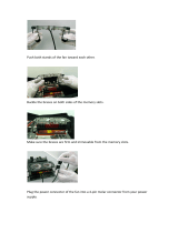
Step 12-6: Place the end of
each table/track conduit into a
slot in the top edge of the frame
ends, as shown in Fig. 12-4.
Note: Make sure that the head
of the cap nuts are on the outer
edge of the frame ends.
Step 12-7: Tighten the cap nuts
completely using the provided
allen wrench.
Step 12-8: Rotate each of the
conduit clamps up, so that they
engage the conduit.
Rotate conduit clamps up, then
tighten bolts completely.
Fig. 12-5
Step 12-10: Place the middle legs under the
table/track conduit.
Note: Make sure that the legs are located in the
center of the frame.
Step 12-11: Rotate each of the conduit clamps
up so that they engage the conduit.
Note: You may need to slightly loosen the bolts
in the conduit caps before the conduit cap can be
turned up.
Step 12-12: Tighten the bolts in the conduit
clamps, so that the conduit is secured in place.
Step 13 - Fabric rail
Parts needed:
4) conduit Spacer
4) fender washer
4) M8 X 70 Hex bolt
12) conduit cap
4) conduit cone
4) 1-1/4” Steel conduit (You provide)
Note: Build 4 (total) fabric rail assemblies. You will need 8 (total) fabric rail conduit caps.
Step 13-1 (fabric rail conduit cap): Build the fabric rail conduit caps by rst inserting a M8 X
70 Hex bolt into the conduit Cone.
Step 13-2: Next, Fit 3 conduit caps together as shown in Fig. 13-1. (The conduit caps may be
held together with a small rubber band.)
Step 13-3: Insert the bolt, and conduit cone into the 3 conduit caps, as shown in Fig. 13-2.
Step 13-4: Place a conduit spacer onto the exposed end of the bolt, and then thread a jam nut
onto the end of the bolt (thread the nut on about 1 inch).
M8 jam nut
conduit spacer
(3) conduit caps
M8 X 70 Hex bolt
conduit cone
Fig. 13-2
Fig. 13-1

Pg.14
Step 13-5: To complete the fabric rail conduit assembly,
insert a fabric conduit cap into each end of the remaining
4 pieces of 1-1/4” conduit. Completely tighten the jam nut
using the provided 8mm wrench.
Note: If you used rubber bands, you can leave the rubber
bands on the caps if you like.
Fig. 13-3
Step 13-6: Place the fabric rails
onto your frame as shown in Fig.
13-4.
Fig. 13-4
Step 13-7: Place a fender washer onto the exposed end of
each bolt.
Step 13-8: Finally, securely fasten a plastic knob onto
the exposed end of the bolts in each end of all of the fabric
rails, as shown in Fig. 13-5.
Fig. 13-5
Step 14 - Bottom plate wheels
Parts needed:
2) Double wheel bearing
4) Single wheel bearing
24) wood screw
1) V- Bottom plate
Step 14-1: Attach each of the wheels to the bottom plate using the provided wood screws, as
shown in Fig. 18-1.
Double wheel
Single wheel
Fig. 14-1

Pg.15
Step 15-1: Build the track conduit caps by rst inserting a M8 X 30 Hex bolt into the conduit cone.
Step 15-2: Fit 3 conduit caps together as shown in Fig. 15-1. (The conduit caps may be held
together with a small rubber band.)
Step 15-3: Insert the bolt, and conduit cone into the 3 conduit caps, as shown in Fig. 15-2.
Step 15-4: Insert the exposed end of the bolt through one of the holes in the bottom plate end.
Step 15-5: Partially thread a cap nut onto the bolt that has just been inserted into the plate end.
Step 15-6: Insert the conduit cap (attached to the bottom plate end) into one end of one of the
bottom carriage tracks.
Step 15-7: Tighten the cap nut that is in the conduit cap completely using the included allen
wrench.
Step 15-8: Repeat steps 15-1 through 15-4, this time insert the bolt
in the conduit cap through the remaining available hole in the bottom
plate end, as shown in Fig. 15-3.
Step 15-9: Attach 2 complete conduit caps
to the remaining bottom plate end, as shown
in Fig. 15-4.
Step 15-10: Insert the end caps into the
open ends of the bottom plate tracks, then
tighten the cap nuts completely.
Fig. 15-3
Fig. 15-4
Fig. 16-1
Step 16 - Bottom plate tracks
Parts needed:
1) Bottom plate - Assembly
1) bottom plate track - Assembly
4) M6 X 45mm connector bolt
4) M6 square nut
Step 16-1: Insert a square nut into each of the “T” slots in the bottom plate ends.
Step 16-2: Secure the bottom plate track assembly to the bottom plate by inserting a M6 X 45mm
connector bolt through each of the holes in the bottom plate, and then tighten securely into the
square nuts (located in the bottom plate track ends).
Step 15 - Bottom plate tracks
Parts needed:
2) U- Bottom plate end
12) conduit cap
4) conduit cone
4) M8 X 30 Hex bolt
2) Bottom carriage track
Fig. 15-1
Fig. 15-2

Pg.16
Step 17-1: Attach each of the wheels to the bottom side of the top plate using the provided 12mm
wood screws, as shown in Fig. 17-1.
Step 18 - Top plate wheels
Parts needed:
1) Top plate - Assembly
1) P- Left handle
1) R- Right handle
4) M6 X 50mm connector Bolt
4: M6 Square nut
Step 18-1: Insert a M6 square nut into each of the slots on the bottom side of the top plate.
Step 18-2: Insert a M6 X 50mm connector bolt through each of the bottom holes on each of the
handles.
Note: Make sure that the pockets in the upper part of the handles face inside the top plate when
attaching the handles to the top plate.
Step 18-3: Thread the M6 X 50mm connector bolts in the handles into the M6 square nuts located
in the slots in the top plate as shown in Fig 18-1.
Fig. 18-1
Step 17 - Top plate wheels
Parts needed:
1) Q- Top plate
2) Double wheel bearing
2) Single wheel bearing
18) 12mm wood screw
Fig. 17-1
Step 19 - Top plate wheels
Parts needed:
1) Top plate - Assembly
1) S1- Thin cross brace
1) S2- Cross brace
1) T- Front top plate brace
4) M6 X 45mm connector bolt
4) M6 square nut
Note: Use the thin cross brace if you will be using a speed control device (such as the Grace Speed
Control, or the Sure Stitch) to control you sewing machine. Fig. 19-1 shows the thin cross brace
being installed. However, if you are going to use the foot pedal that was included with your sewing
machine, install the cross brace (not shown) instead of the thin cross brace.
thin cross brace
Front top
plate brace
Double wheel
Single wheel

Pg.17
Step 20 - Lever to top plate
Parts needed:
1) Top plate - Assembly
1) W- Front lever
1) X- Middle lever
1) Y1- Right back lever (not shown)
1) Y2- Left back lever
3) M6 X 50mm Connector Bolt
3) M6 nylock nut
6) M6 washer
Note: You may assemble the levers to the left, or right side of the top plate. The assembly will be a
mirror of what is shown in Fig. 20-1, also use the right back lever for the right side assembly.
Step 20-1: Attach the levers to the top plate by rst inserting a M6 X 50mm connector bolt through
the indicated holes in each lever.
Step 20-2: Next place a M6 washer onto the exposed end of the bolt that you just inserted into the
lever(s).
Step 20-3: Now place the bolt(s) through the indicated holes in the handle.
Step 20-4: Place a M6 washer onto the end of each bolt.
Step 20-5: Secure the levers to the handle by threading a M6 nylock nut onto the bolts.
Note: Do not completely tighten the nylock nuts. You should be able to easily turn the M6 washer
behind the nylock nut.
Step 19-1: Insert a M6 square nut into each of the “T” slots in the T- lamp holder brace. Also
insert a M6 square nut into the “T” slots in which ever cross brace you have decided to use.
Step 19-2: Place each of the braces into the pockets in the top of the handles, as shown in Fig.
19-1.
Note: You may need to pull the handles apart slightly to get the braces between them.
Step 19-3: Secure the braces to the handles buy inserting a M6 X 45mm connector bolt through
each of the indicated holes in the handles, and then tighten it securely into the M6 square nut with
the included allen wrench.
Note: If you used the thin cross brace, please skip to step 23 to complete the quilt frame assembly.
If you used the cross brace, please continue with the next step.
Front lever
Middle lever
Left back lever

Pg.18
Step 21 - Lever linkage
Parts needed:
2) M6 X 45mm connector bolt
2) M6 X 50mm connector bolt
8) M6 washer
4) M6 nylock nut
1) top plate (Assembly)
1) Z- front lever linkage
1) AA- back lever linkage
Step 21-1: Attach the lever linkage parts (front lever linkage,
and back lever linkage) to the levers, as shown in Fig. 21-1.
Note: Use the M6 X 50mm, and M6 X 45mm bolts in the
locations specied.
M6 X 45mm connector bolt
M6 X 50mm connector bolt
M6 washer
M6 nylock nut
Step 22 - Pedal clamp
Parts needed:
1) M8 X 75 carriage bolt
1) M8 jam nut
1) fender washer
1) plastic knob
1) M6 X 50mm connector bolt
1) M6 washer
1) N6 nylock nut
1) BB- pedal clamp wheel
1) CC- pedal clamp
3) DD- pedal clamp spacer
Step 22-1: Insert the M8 X 75mm carriage
bolt through the hole in the top end of the
middle lever.
Step 22-2: Place 3 of the pedal clamp spacers onto the end of the carriage bolt.
Note: Make sure that the last pedal clamp spacer has it’s cupped side facing the end of the bolt.
Step 22-3: Secure the pedal clamp spacers in place with the M8 jam nut.
Step 22-4: Place the pedal clamp onto the end of the carriage bolt.
Step 22-5: Now place a fender washer onto the bolt.
Step 22-6: Thread on a plastic knob to secure the pedal clamp to the lever.

Pg.19
Step 22-7: Insert the M6 X 50mm connector bolt
through the hole in the pedal clamp wheel.
Step 22-8: Place a M6 washer onto the exposed
end of the bolt.
Step 22-9: Place the end of the bolt through the
hole in the bottom of the pedal clamp.
Step 22-10: Put a M6 washer onto the end of the
bolt.
Step 22-11: Finally, secure the pedal
clamp wheel to the pedal clamp using a M6
nylock nut.

Pg.20
Step 23 - Stylus clamp
Parts needed:
Hardware:
2) M8 X 75mm carriage bolt
2) M8 jam nut
3) fender washer
3) plastic knob
1) M8 X 50mm eye bolt
2) M8 washer
1) EE- stylus base (Smaller holes)
1) FF- stylus clamp
1) GG- stylus mount
1) HH- stylus
M8 X 75mm carriage bolt
stylus base
M8 washer
M8 jam nut
stylus clamp
stylus mount
fender washer
plastic knob
plastic knob
fender washer
eye bolt
stylus
Step 23-1: Insert M8 X 75mm carriage bolt
through each of the holes in the stylus base.
Step 23-2: Secure the carriage bolts to the
stylus base using M8 washers, and M8 jam nuts.
Step 23-3: Place the stylus mount onto the bolt
closest to the curved end of the stylus base.
Step 23-4: Place the stylus clamp onto the
exposed ends of both bolts as shown if Fig. 23-2.
Step 23-5: Secure the stylus clamp to the rest
of the assembly by rst placing a fender washer
onto the exposed ends of the bolts, and then
threading a plastic knob onto each bolt. (The
knobs do not need to be tightened completely at
this point.)
Fig. 23-1
Fig. 23-2
Fig. 23-3
Step 23-6: Insert the eyebolt through the cupped side of the stylus
mount.
Step 23-7: Secure the eye bolt to the assembly by rst placing a
fender washer onto the exposed end of the bolt, and then threading a
plastic knob partially onto the bolt.
Step 23-8: Finally, insert the stylus through the open end of the eye
bolt.
Step 23-9: Adjust the knob on the eye bolt to allow the stylus to be
inserted through the open end of the eye bolt, and then secure the
stylus in place.
Note: The stylus accessory can be attached to the carriage in many
locations, but is not required for use of the quilt frame.
Use the stylus to trace pantographs
Fig. 23-4
/