Page is loading ...

The Little Gracie
Home Machine Quilting System
Parts Lists
Frame Parts List. . . . . . . . . . . . . . . . . . . . . . . . . . . . . . . . . . . . . . . . . . . . . . . . . . . . . . . .2
Carriage Assembly Parts List. . . . . . . . . . . . . . . . . . . . . . . . . . . . . . . . . . . . . . . . . . . . . .5
Care of Your Frame. . . . . . . . . . . . . . . . . . . . . . . . . . . . . . . . . . . . . . . . . . . . . . . . . . . 7
Assembly Steps:
Step 1: Brace Mount Side Assembly. . . . . . . . . . . . . . . . . . . . . . . . . . . . . . . . . . . . . . . .8
Step 2: Front Pole Mount End Assembly.. . . . . . . . . . . . . . . . . . . . . . . . . . . . . . . . . . .9
Step 3: Rail Retainer Assembly.. . . . . . . . . . . . . . . . . . . . . . . . . . . . . . . . . . . . . . . . . . .10
Step 4: Back Pole Mount Assembly. . . . . . . . . . . . . . . . . . . . . . . . . . . . . . . . . . . . . . . 10
Step 5: Right Brace Mount Assembly. . . . . .. . . . . . . . . . . . . . . . . . . . . . . . . . . . . . . . . 11
Step 6: Right Brace To Leg Assembly. . . . .. . . . . . . . . . . . . . . . . . . . . . . . . . . . . . . . . 12
Step 7: Left Brace Side Mount Assembly . . . . . . . . . . . . . . . . . . . . . . . . . . . . . . . . . . 13
Step 8: Left Brace To Leg Assembly . . . . . . . . . . . . . . . . . . . . . . . . . . . . . . . . . . . . . .13
Step 9: Attaching the Right and Left Brace Assembly . . . . . . . . . . . . . . . . . . . . . . . .14
Step 10: Leg Angle Brace Assembly. . . . . . . . . . . . . . . . . . . . . . . . . . . . . . . . . . . . . . .16
Step 11: Rear Angled Brace Assembly . . . . . . . . . . . . . . . . . . . . . . . . . . . . . . . . . . . . 18
Step 12: Left and Right Frame End Assembly . . . . . . . . . . . . . . . . . . . . . . . . . . . . . . 18
Step 13: Front Pole Mount End to Frame Ends . . . . . . . . . . . . . . . . . . . . . . . . . . . . 19
Step 14: Back Pole Mount Ends to Frame Ends . . . . . . . . . . . . . . . . . . . . . . . . . . . . 20
Step 15: Third Rail Retainer Assembly. . . . . . . . . . . . . . . . . . . . . . . . . . . . . . . . . . . . 20
Step 16: Rail Assembly. . . . . . . . . . . . . . . . . . . . . . . . . . . . . . . . . . . . . . . . . . . . . . . . . 21
Step 17: Rail to Frame Assembly And Adjustment. . . . . . . . . . . . . . . . . . . . . . . . . . 22
Step 18: Track Platform Assembly . . . . . . . . . . . . . . . . . . . . . . . . . . . . . . . . . . . . . . 23
Step 19: Track to Track Platform Assembly. . . . . . . . . . . . . . . . . . . . . . . . . . . . . . . 26
Step 20: Ratchet Stop Assembly. . . . . . . . . . . . . . . . . . . . . . . . . . . . . . . . . . . . . . . . . 27
Step 21: Carriage Stop Assembly. . . . . . . . . . . . . . . . . . . . . . . . . . . . . . . . . . . . . . . 28
Step 22: Edgemaster Assembly. . . . . . . . . . . . . . . . . . . . . . . . . . .. . . . . . . . . . . . . . .29
Carriage Sub-Assemblies:
Step 1: Wheels to Top and Bottom Plates. . . . . . . . . . . . . . . . . . . . . . . . . . . . . . . . .32
Step 2: Hardware to Pedal Supports. . . . . . . . . . . . . . . . . . . . . . . . . . . . . . . . . . . . .33
Step 3: Handle and Supports to Top Plate. . . . . . . . . . . . . . . . . . . . . . . . . . . . . . . .34
Step 4: Upper Handles to Carriage Assembly. . . . . . . . . . . . . . . . . . . . . . . . . . . . . .35
Step 5: Platform and Brace to Carriage Assembly. . . . . . . . . . . . . . . . . . . . . . . . . 36
Step 6: Upper Speed Control to Carriage Assembly. . . . . . . . . . . . . . . . . . . . . . . . 37
Step 7: Hardware to Pedal Support. . . . . . . . . . . . . . . . . . . . . . . . . . . . . . . . . . . . . 38
Step 8: Lower Speed Control to Carriage Assembly. . . . . . . . . . . . . . . . . . . . . . . . 38
Step 9: Pedal Clamp to Carriage Assembly. . . . . . . . . . . . . . . . . . . . . . . . . . . . . . . 39
Step 10: Stylus Arm to Carriage Assembly. . . . . . . . . .. . . . . . . . . . . . . . . . . . . . . 40
Step 11: Stylus Clamp Assembly. . . . . . . . . . . . . . . . . . . . . . . . . . . . . . . . . . . . . . .40
Step 12: Installing the Sewing Machine and Foot Pedal. . . . . . . . . . . . . . .. . . . . . 42
Fabric Installation and Use of Frame. . . . . . . . . . . . . . . . . . . . . . . . . . . . . . . . .43
Method #1: Hemming Your Fabric
Method #2: Cloth Leaders
Placing the Top and Bottom Plates onto the Table
Rolling your fabric
The Four-Inch Principle
Carriage Stop Assembly
Turning Your Quilt Around
Optional Fourth Pole Assembly
Trouble Shooting Tips
Sewing Machine Tips
Available Accessories
Patent Pending
Copyright February 2004
Jim M. Bagley, GraceWood, Inc.
(Reproduction Prohibited)

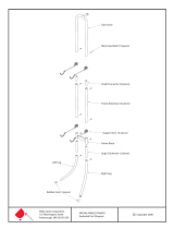
2
1-Left Frame End 1-Right Frame End
1-Right Front
Pole Mount End
1-Right Back
Pole Mount End
1-Left Front
Pole Mount End
1-Left Back
Pole Mount End
1-Right Brace Side Mount
1-Left Brace Side Mount
2-Short Cross Brace
3-Middle Cross Brace
2-Long Brace
2-Short Brace
2-Middle Brace
1-Right Rear
Angle Brace
1-Left Rear
Angle Brace
8-Leg
1-Right 3rd
Rail Retainer
8-Leg Angle Brace
1-Left 3rd
Rail Retainer
2-Carriage
Stop Spacer
4-Carriage
Stop Side
Little Gracie Frame
Parts List

3
1-Left Track Platform
1-Middle Track Platform
1-Right Track Platform
3-64" Rail
3-Ratchet
Wheel
3-Square
End Cap
6-End Cap
Shoulder
3-Round
End Cap
1-107 7/8" Track
1-99 1/8" Track
1-73 7/8" Track
1-65 1/8" Track
Edgemaster Parts List
3-Ratchet
Stop
1-Right Narrow Track Platform
1-Middle Narrow Track Platform
1-Left Narrow Track Platform
2-94" Fabric
Retaining Tube
1-Right Edgemaster Base1-Left Edgemaster Base
1-Right Clamping Bar1-Left Clamping Bar
1-Right Cam
2-Edgemaster Dowel
2-Edgemaster Sleeve
1-Left Cam
3-34" Rail

4
54-1/4" X 45mm
Connector Bolt
32-1/4" X 30mm
Connector Bolt
3-1/4" X 1 1/2"
Truss Bolt
6-7/8" Screws
2-1/4" X 1"
Hex Bolt
34-1/4" Flat
Washer
16-1/4" Jamb
Nut
4-1/4" Nylock
Nut
12-1/4" Plastic
Knob
32-1/4" Cap
Nut
Edgemaster Hardware
6-1/4" X 35mm
Connector Bolt
12-1/4" Flat
Washer
6-1/4" Jamb
Nut
6-1/4" Nylock
Nut
38-1/4" Rectangle
Nut
2-4mm Allen
Wrench
2-1/4 X 4"
Carriage Bolt
Little Gracie Frame Hardware
***Drawings display hardware in actual size***

5
1-Right Lower Handle1-Left Lower Handle
1-Left Pedal Support
1-Right Pedal Support
Carriage Assembly
Parts List
1-Right Upper Handle
1-Left Upper Handle
1-Pedal Platform
1-Lower Speed
Control Levcr
1-Lower Lever Linkage
1-Pedal
Clamp
1-Upper Speed
Contol Lever
1-Lever Spacer
1-Stylus Arm
1-Stylus Clamp
1-Top Plate
1-Bottom Plate
1-Upper Lever Linkage
1-Upper Handle
Brace
1-Stylus
1-Pedal Clamp
Wheel

6
5-1/4" X 50mm
Connector Bolt
14-1/4" X 45mm
Connector Bolt
8-1/4" X 1"
Hex Bolt
23-1/4" Flat
Washer
19-1/4" Nylock
Nut
3-1/4" Plastic
Knob
6-1/4" Cap
Nut
6-1/4" Rectangle
Nut
4-1/4" X 30mm
Connector Bolt
1-1/4" X 2"
Eye Bolt
8-Wheel
1-8mm X 25mm
Hex Bolt
Carriage Assembly Hardware
***Drawings display hardware in actual size***

7
CARE OF YOUR LITTLE GRACIE
Your Little Gracie frame is a machine quilting system that can be used finished or unfinished. Most use it
unfinished with no problem, and doing so does not adversely affect warranty coverage. However, for extra
protection, or to give it a finished look, you may seal, stain and/or finish the frame using a number of different
applications. This is best done BEFORE YOU ASSEMBLE your frame.
To seal the wood, we recommend an application of tung oil or Danish Oil finish that will help preserve
the wood and will help to prevent warping. We recommend the McCloskey’s Tung Seal, Deft
TM
or Watco
TM
brands. Some prefer to use a urethane coat to add a more glossy finish.
Test stain on an inconspicuous place. Many different finishes and/or stains may be suitable for sealing
and beautifying your frame. You may want to consult your local paint retailer for finishes that are easy to apply
and dry hard–not oily.
Use and Storage Tip
--Store frame in a dry place. If not assembled, store with braces in vertical position. (This will prevent floor
moisture from seeping into the parts).
Five-Year Limited Warranty
GraceWood, Inc. will replace or repair, at our choosing, any part of the Little Gracie
Machine Quilting
System, which may be shown to be defective. This warranty does not cover parts damaged through misuse,
improper storage, improper assembly, loss, natural events and willful or accidental destruction. Defective parts
may be returned only with a valid RMA# which may be obtained by calling GraceWood, Inc. at
1-800-264-0644.
NOTE: Warranty card must be filled out, stamped and mailed to the address on the card within 30 days of
purchase.
Contact Information
For Technical Support or any other correspondence concerning your Little Gracie, call 1-800-264-0644 ~
OR ~ E-mail: [email protected] ~ OR ~ Fax: (801) 908-8888 ~
OR ~ Write to:
The Grace Company
P.O. Box 27823
Salt Lake City, UT 84127
For details on accessories and other information, see us online at www.graceframe.com
For shipping of materials to The Grace Company address package (postage prepaid) to: The Grace Company,
2225 South 3200 West, SLC, UT 84119. Materials may be returned only with a valid RMA# or Returned
Merchandise Authorization Number which may be obtained by calling GraceWood, Inc. at
1-800-264-0644.
If you call after business hours (M-F 8:00 a.m. – 5 p.m., MST) be assured that your call will be returned
the next business day if you leave a message. Please report any errors in these instructions or make comments
to the following: jaren@graceframe.com
Grace Quilting Frames and Hoops: Innovation and Evolution
Grace Quilting Systems have been developed over the past two decades with several original design
innovations. Additionally, because of feedback from many of the thousands of quilters who have purchased and
use our machine quilting systems, we have been able to make a frame that will truly enhance the entire process
of machine quilting from beginning to end. If you have any suggestions that will help us to improve our
product or service, let us know, using one of the above contact methods.
WELCOME!

8
As you begin assembly of your new Little Gracie home machine quilting system, keep in the mind the
following:
1) Plan to spend a minimum of 3-4 hours in assembly. This process will be simple and step-by-step.
2) Read through each step completely before beginning that step.
3) Using the parts list as a reference, take the parts out of both boxes and make sure that you have them all. (If there is
something missing or broken, contact the Grace Company 1-800-264-0644. Our offices are open from 8:00 am-5:00 pm MST
Mon.-Fri. If calling after hours, you may leave your message and we will promptly ship any item needed).
4) For your convenience, an “L” and “R” have been etched into the INSIDES of most pieces to help you distinguish between
left and right parts and inside and outside of parts.
5) Packaging Note: The dowels are packaged inside the aluminum rails.
6) Identify Hardware Packets: Frame Hardware Packet (F), Carriage Assembly Hardware Packet (CA). For ease in
identifying bolts, keep the “CA” packet sealed until you work on the Carriage Sub-Assemblies.
7) This is a new product! We welcome your feedback on this product or these instructions. If you encounter a problem
during assembly or use of the Little Gracie, and you can’t seem to overcome it, call us before frustration sets in!
Tools Needed:
7/16” Socket Wrench
Adjustable wrench
Phillips Screw Driver
Allen wrench (provided)
Step 1: Brace Mount Side Assembly
Parts Needed: 1 – Right and Left Brace Mount
4 – 45mm Connector Bolt
4 – ¼” Flat Washer
4 – ¼” Jamb Nut
¾ Open the hardware packet labeled “F” and
empty the contents for use in this first half of
assembly
¾ Thread two 45mm connector bolts through
the two holes of the Right Brace Mount as
pictured, starting from the INSIDE of the
brace.
¾ Place a ¼” flat washer and ¼” jamb nut onto
the end of each bolt. Using a 7/16” wrench,
TIGHTEN THE JAMB NUTS COMPLETELY ONTO EACH
BOLT.
¾ Repeat these steps for the Left Side.
¾ These bolts will be connected to in a later step.
Step 2: Front Pole Mount End Assembly
Parts Needed: 1 – Right and Left Front Pole Mount Ends
1/4" Jamb
Nut
1/4" Flat
Washer
1/4" X 45mm
Connector Bolt
Right Brace Mount Side Assembly
Inside View
Left Brace Mount Side Assembly
Inside View
1/4" Jamb
Nut
1/4" Flat
Washer
1/4" X 45mm
Connector Bolt

9
4 – ¼” x 45mm Connect Bolt
4 – ¼” Flat Washer
4 – ¼” Jamb Nut
¾ Thread two 45mm connector bolts through the two holes of the Right Front Pole Mount End as pictured,
starting from the INSIDE of the part.
¾ Place a ¼” flat washer and ¼” jamb nut onto the end of each bolt.
¾
.
¾ Using a 7/16” wrench, TIGHTEN THE
JAMB NUTS COMPLETELY ONTO
EACH BOLT (you will need to steady the
45 mm connector bolts with an allen
wrench while you tighten).
¾ Repeat these steps for the Left Side.
Step 3: Rail Retainer Assembly
Parts Needed: 1 – Right and Left 3
rd
Rail Retainer
2 – ¼” x 1” Hex Bolt
Right Front Pole Mount End
Inside View
1/4" X 45mm
Connector Bolt
1/4" Flat
Washer
1/4" Jamb
Nut
Left Front Pole Mount End
Inside View
1/4" X 45mm
Connector Bolt
1/4" Flat
Washer
1/4" Jamb
Nut

10
4 – ¼” Flat Washer
2 – ¼” Jamb Nut
¾ First, place a ¼” flat washer
onto a ¼” x 1” hex head bolt.
¾ Next, place the hex head bolt
through the hole of the Right 3
rd
Rail Retainer, starting from the
OUTSIDE of the part, as
pictured.
¾ Put another ¼” flat washer onto
the end of the bolt.
¾ Thread a ¼” jamb nut onto the hex bolt and
COMPLETELY TIGHTEN using a 7/16” wrench on
both the nut and the bolt head.
¾ Repeat these steps for the left side.
Step 4: Back Pole Mount Assembly
Parts Needed: 1 – Right and Left Back Pole Mount End
4 – ¼” x 45mm Connector Bolt
4 – ¼” Flat Washer
4 – ¼” Jamb Nut
¾ Place two 45mm connector bolts throught the
two holes, as pictured, from the inside of the
part.
1/4" X 1"
Hex Bolt
1/4" Flat
Washer
1/4" Jamb
Nut
Left 3rd Rail Retainer
Inside View
Right 3rd Rail Retainer
Inside View
1/4" Jamb
Nut
1/4" Flat
Washer
1/4" X 1"
Hex Bolt
Right Back Pole Mount End
Inside View
1/4" Jamb
Nut
1/4" Flat
Washer
1/4" X 45mm
Connector Bolt
Left Back Pole Mount End
Inside View
1/4" Jamb
Nut
1/4" Flat
Washer
1/4" X 45mm
Connector Bolt

11
¾ Place one ¼” flat washer on each bolt.
¾ Thread a ¼” jamb nut onto the end of each bolt and tight completely.
¾ Repeat these steps for the Left Side (see right).
Step 5: Right Brace Mount Assembly
Parts Needed: 1 – Short Brace
1 – Short Cross Brace
1 – Long Brace
1 – Right Brace Mount Side
4 – ¼” x 45mm Connector Bolt
8– ¼” Rectangle Nut
¾ Next, you will connect the Right Brace Mount Assembly, using 45 mm connector bolts and rectangle nuts.
¾ Locate the Short Brace and Long Brace and place them opposite each other, with “t” slots facing inside.
¾ Locate the Right Brace Mount and Short Cross Brace and place them opposite each other, with slots facing
inside, as pictured.
¾ Connect the braces together by threading 45mm connector bolts through the holes of the brace and into the
rectangle nuts. (Hold the rectangle nuts in place, while using the provided allen wrench to tighten these
bolts).
¾ Place rectangle nuts vertically in the “t” slots, as illustrated below.
Short Brace
Long Brace
Short Cross
Brace
Right Brace
Mount Side
1/4" X 45mm
Connector Bolt
1/4" Rectangle
Nut

12
¾ With this assembly
completed, place ¼”
rectangle nuts in the
horizontal slots—two in
the Short Cross Brace,
and two in the Right
Brace Mount as
pictured. (These need to
be in place before you
fasten the legs in the
next step).
Step 6: Right Brace to
Leg Assembly
Parts Needed: 4 -- Legs
8 – ¼” x 30 mm Connector Bolt
8 – ¼” Cap Nut
¾ Next, position two legs inside the Short Cross
Brace, lining the two holes at the top of the
legs, with the holes in the Cross Brace.
(NOTE: Be sure the legs are right side up—
there are five holes near the top end of each
leg).
¾ NOTE! Before connecting the legs, make
sure the rectangle nuts are in the
horizontal slots discussed at the end of the
last step.
¾ Connect these legs to the Cross Brace by
placing ¼” cap nuts through the two leg
holes and two 30mm connector bolts through
the holes of the Cross Brace.
¾ Place and allen wrench in the heads of both
the cap nut and bolt to tighten. Do this for all
four bolts.
¾ Repeat this procedure for the other two legs
on the Right Brace Mount.
¾ Set aside this assembly. You will now repeat Steps 5 and 6 for the Left Side.
Step 7: Left Brace Side Mount Assembly
Parts Needed: 1 – Left Brace Side Mount
1/4" Rectangle
Nut
1/4" X 30mm
Connector Bolt
1/4" Cap
Nut
Leg

13
1 – Short Brace
1 – Long Brace
1 – Short Cross Brace
4 – ¼” x 45mm Connector Bolt
8 – ¼” Rectangle Nut
¾ Assembly the Left Brace Side
Mount Assembly following
the same procedure as in Step
5.
¾ Be sure the slots in the Brace
pieces are facing inside.
¾ Again place four rectangle
nuts in the horizontal slots as
you did in Step 5.
Step 8: Left Brace to Leg Assembly
Parts Needed: 4 – Legs
8 – ¼” x 45mm Connector Bolt
8 – ¼” Cap Nut
¾ Now follow the same procedures as in Step 6 to
connect the Left Brace Assembly to the four legs,
being sure the four rectangle nuts are in place
before you connect the legs.
Step 9: Attaching the Right and Left Brace Assembly
Short Brace
Long Brace
Short Cross
Brace
Left Brace
Side Mount
1/4" X 45mm
Connector Bolt
1/4" Rectangle
Nut
1/4" Rectangle
Nut
1/4" X 45mm
Connector Bolt
1/4" Cap
Nut

14
Parts Needed: 2 – Middle Brace
1 or 3* – Middle Cross Brace
4 – ¼” x 30mm Connector Bolt
4 – ¼” Cap Nut
2 or 6* – 45 mm Connector Bolt
2 or 6* – Rectangle Nut
*For queen size assembly
¾ Next, you will connect the left and right leg
assemblies using the Middle Braces.
¾ Place the ¼” cap nuts in the holes located at the
ends of the middle brace and long brace.
¾ Put 30mm connector bolts through the slots of
the long and middle braces and into the cap
nuts. Do not completely tighten at this time.
A
1/4" X 30mm
Connector Bolt
1/4" Cap
Nut
A
Place the Cap Nuts in the holes and the
Connector Bolts in the slots

15
¾ Next, place one Middle Cross
Brace as pictured (left) in
between to the two Short Cross
Braces and connect it to the
front and back Middle Braces.
¾ This is done by placing
rectangle nuts in the slots of the
Cross Brace and threading
45mm connector bolts through
the Cross Brace holes and into
the rectangle nuts.
¾ If you are setting up the crib size
frame, this step is now
complete.
MAKING THE QUEEN SIZE
¾ To complete your queen size set-up,
pull your frame ends out so the middle
braces extend their furthest.
¾ Place connect all three Middle Cross
Braces, as pictured (see right).
¾ Connect them to the front and back
Middle Braces by placing rectangle
nuts in the slots of the Middle Cross
Braces and threading 45 mm connector
bolts through the Middle Brace slots
and into the rectangle nuts.
1/4" X 45mm
Connector Bolt
1/4" Rectangle
Nut
1/4" Rectangle
Nut
1/4" X 45mm
Connector Bolt
1/4" X 45mm
Connector Bolt
1/4" Rectangle
Nut

16
Step 10: Leg Angle Brace Assembly
Parts Needed: 8 – Leg Angle Braces
8 – ¼” Cap Nuts
12 or 8* – ¼” x 45mm Connector Bolts
4 or 8* – ¼” x 30mm Connector Bolts
8 – ¼” Rectangle Nuts
*Queen Size Assembly
¾ In this step, you will connect a
Leg Angle Brace to each Leg in
the assembly. (Note: Slotted end
of Leg Angle Brace is down,
toward Leg).
¾ First connect the Leg Angle Brace
to each Leg using a 45 mm
connector bolt and rectangle nut.
(see closeup below).
¾ Tighten the connector bolt using
the Allen wrench.
¾ Next, connect the other end of the
Leg Angle Brace to the Brace by
placing a 30 mm connector bolt
through the Brace hole and into
the hole in the Leg Angle Brace.
¾ Then, place a cap nut
through the other side of the
Leg Angle Brace hole and
thread it onto the connector
bolt. Use both Allen
wrenches to tighten these
completely.
¾ If setting up the queen size,
repeat this procedure for all
remaining Leg Angle
Braces.
1/4" X 30mm
Connector Bolt
1/4" X 45mm
Connector Bolt
1/4" Rectangle
Nut
1/4" Cap
Nut
Leg Angle Brace
Assembly Close Up
A

17
¾ This illustration (right)
shows the queen size
set-up. Detail for the
crib size assembly is
below.
¾ If you are setting
up your frame in
the Crib Size, the
Leg Angle Braces
connected to the
outside legs are
assembled as stated
above.
¾ However, the Leg
Angle Brace
connecting to the
inside Legs are
different: they
connect to the
Braces using 45
mm connector
bolts and cap nuts,
instead of 30 mm
bolts (see left).
1/4" X 30mm
Connector Bolt
1/4" X 30mm
Connector Bolt
1/4" X 45mm
Connector Bolt
1/4" Rectangle
Nut
1/4" Cap
Nut
1/4" X 45mm
Connector Bolt

18
Step 11: Rear Angled Brace Assembly
Parts Needed: 1 – Left and Right Rear Angle Brace
4 – ¼” x 45mm Connector Bolts
4 – ¼” Rectangle Nuts
¾ Next, connect the Left and Right Rear Angle
Braces to your assembly using 45 mm
connector bolts and rectangle nuts on each end
of the Braces.
¾ Note! Be sure and use the part marked “R”
for the right side and “L” for the left side
(letter facing down, as pictured)
Step 12: Left and Right Frame End Assembly
Parts Needed: 1 – Left and Right Frame End
4 – ¼” Flat Washer
4 – ¼” Black Plastic Knob
¾ Connect the Right Frame End (with the “R” facing
inside) to the Right Side Mount by placing the
horizontal slots at the bottom of the mount to the
bolts on the Mount.
¾ Place a ¼” flat washer onto the ends of each bolt,
once they are through the slots.
¾ Next, thread a ¼” plastic knob onto the end of each
bolt and hand tighten.
¾ Repeat this procedure for the Left Frame End and
Left Side Mount.
1/4" X 45mm
Connector Bolt
1/4" Rectangle
Nut
Right Rear
Angle Brace
Left Rear
Angle Brace
1/4" X 45mm
Connector Bolt
1/4" Rectangle
Nut
Right Frame End
1/4 Flat
Washer
1/4" Knob

19
Step 13: Front Pole Mount End to Frame Ends
Parts Needed: 1 – Left and Right Front Pole Mount End
4 – ¼” Flat Washers
2 – ¼” Black Plastic Knob
2 – ¼” Nylock Nut
¾ Attach the Right Front Pole Mount
End, with previously installed
hardware, to the Right Frame End as
pictured below.
¾ Be sure the “R” is right-side-up facing
toward the inside of the frame.
¾ With the two bolts going through the
front vertical slot of the Right Frame
End, place a ¼” flat washer onto the
end of each bolt.
¾ Next, thread a ¼” plastic knob onto
the top bolt.
¾ Thread a ¼” nylock nut onto the
bottom bolt and tighten just enough to
allow the washer to still spin.
¾ Repeat this procedure for the Left
Front Pole Mount End.
1/4" Flat
Washer
1/4" Nylock
Nut
1/4" Knob
1/4" Knob
1/4" Nylock
Nut
1/4" Flat
Washer

20
Step 14: Back Pole Mount Ends to Frame Ends
Parts Needed: 1 – Left and Right Back Pole Mount End
4 – ¼” Flat Washers
2 – ¼” Black Plastic Knobs
2 – ¼” Nylock Nut
¾ The Right Back Pole Mount End will connect to the
back slot of the Right Frame End as pictured (see
right).
¾ Again, be sure the “R” is right-side-up facing toward
the inside of the frame.
¾ With the two bolts going through the back vertical
slot of the Right Frame End, place a ¼” flat washer
onto the end of each bolt.
¾ Next, thread a ¼” plastic knob onto the top bolt.
¾ Thread a ¼” nylock nut onto the bottom bolt and
tighten just enough to allow the washer to still spin.
¾ Repeat this procedure for the Left Back Pole Mount
End.
Step 15: Third Rail Retainer Assembly
Parts Needed: 1 – Left and Right 3
rd
Rail Retainers
2 – ¼” Flat Washers
2 – ¼” Black Plastic Knobs
¾ Next, connect the Right 3
rd
Rail Retainer to the
bottom of the Back Pole Mount End, as pictured.
¾ Place the previously installed bolt through the hole
in the bottom of the Back Pole Mount End.
¾ Place a ¼” flat washer and ¼” plastic knob onto the
end of the bolt and hand tighten.
¾ Repeat this procedure for the left side.
¾ This completes the Left and Right End assembly.
1/4" Knob
1/4" Flat
Washer
1/4" Knob
1/4" Nylock
Nut
1/4" Flat
Washer
1/4" Flat
Washer
1/4" Nylock
Nut
1/4" Knob
/