Page is loading ...

Model 3020
PULL-TYPE
WINDROWER
OPERATOR’S MANUAL
Form 147021 Issue 06/03
Sugg. Retail: $15.00

i
INTRODUCTION
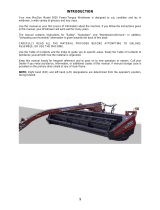
Your new Pull-Type Windrower is designed to cut, and lay in windrows, a wide variety of grain and specialty
crops. Windrowing allows starting the harvest earlier, protects the crop from wind damage, and gives you more
flexibility in scheduling combine time.
Use this manual as your first source of information about the machine. If you follow the instructions given in
this manual, your Windrower will work well for many years.
The manual contains instructions for "Safety", "Operation", and "Maintenance/Service". A separate booklet
provides information on "Unloading and Assembly".
CAREFULLY READ ALL THE MATERIAL PROVIDED BEFORE ATTEMPTING TO UNLOAD, ASSEMBLE,
OR USE THE MACHINE.
Use the Table of Contents and the Index to guide you to specific areas. Study the Table of Contents to
familiarize yourself with how the material is organized.
Keep this manual handy for frequent reference and to pass on to new operators or owners. Call your Dealer if
you need assistance, information, or additional copies of this manual.
NOTE: Right hand (R/H) and left hand (L/H) designations are determined from the operator's position, facing
forward.

ii
TABLE OF CONTENTS
PAGE
INTRODUCTION................................................................................................................................... i
SERIAL NUMBER LOCATION .............................................................................................................v
SAFETY
Safety Alert Symbol......................................................................................................................... vi
Signal Words................................................................................................................................... vi
Safety Signs.................................................................................................................................vii, viii
General Farm Safety..................................................................................................................... ix, x
SPECIFICATIONS
Windrower........................................................................................................................................1
Tractor Requirements ......................................................................................................................1
Hardware Torque Specifications......................................................................................................2
Hydraulic Fitting Torque Specifications............................................................................................3
OPERATION
Your Responsibilities as an Owner/Operator...................................................................................4
To the New Operator........................................................................................................................4
Preparing the Tractor ..................................................................................................................... 5,6
Preparing the Windrower ............................................................................................................... 7,8
Attaching Windrower to Tractor..................................................................................................... 9,10
Detaching Windrower from Tractor .............................................................................................. 11,12
Break-In Period ...............................................................................................................................13
Pre-Starting Checks: Annual...........................................................................................................14
Pre-Starting Checks: Daily..............................................................................................................15
Operate Correctly............................................................................................................................16
Engaging the PTO...........................................................................................................................17
Cutting Width...................................................................................................................................17
Right Hand Divider Rod ..................................................................................................................17
Header Lock....................................................................................................................................18
Cutting Height (minimum header height adjustment)......................................................................18
Ground Speed.................................................................................................................................19
Reel Speed .....................................................................................................................................20
Reel Props ......................................................................................................................................21
Reel Height .....................................................................................................................................21
Reel Position - Fore and Aft............................................................................................................22
Draper Speed..................................................................................................................................23
Delivery Opening Width ............................................................................................................... 24,25
Delivery Opening Height .................................................................................................................26
Levelling the Cutterbar....................................................................................................................26
Windrow Characteristics .................................................................................................................27
Cornering ........................................................................................................................................28
Field Light........................................................................................................................................28
Unplugging the Sickle .....................................................................................................................29
Shut-Down Procedure.....................................................................................................................29
Transporting the Windrower......................................................................................................... 30,31
Transport Width...............................................................................................................................31
Converting from Field Position to Transport................................................................................. 32,33
Converting from Transport to Field Position................................................................................. 33,34
Storage Procedure..........................................................................................................................35

iii
TABLE OF CONTENTS
PAGE
MAINTENANCE/SERVICE
Service Procedures.........................................................................................................................36
Greasing the Windrower ..............................................................................................................37-41
Telescoping Hitch Pin .....................................................................................................................42
Left Wheel Lock Assembly..............................................................................................................42
Header Flotation..............................................................................................................................42
Hydraulics .................................................................................................................................... 43,44
Removal of Header Lift Cylinder .....................................................................................................44
Electrical..........................................................................................................................................45
Main Drives:
Belt Alignment...............................................................................................................................46
Idler Pulley Shield Alignment ........................................................................................................46
Belt Tension ..................................................................................................................................47
Removal of Main Drive Pulley.......................................................................................................47
Sickle and Sickle Drive:
Sickle Lubrication..........................................................................................................................48
Sickle Sections..............................................................................................................................48
Sickle Removal and Installation ....................................................................................................49
Pitman Replacement.....................................................................................................................49
Guards ..........................................................................................................................................50
Excessive Breakage......................................................................................................................50
Sickle Hold-Downs........................................................................................................................50
Sickle Register ..............................................................................................................................51
Sickle Drive Belt Tension ..............................................................................................................52
Reel and Reel Drive:
Reel Clearance from Cutterbar .....................................................................................................53
Centering the Reel ........................................................................................................................54
Reel Primary Drive Belt Tension...................................................................................................55
Reel Final Drive Belt Tension........................................................................................................55
Drapers and Draper Drive:
Draper Care ..................................................................................................................................56
Draper Tracking ......................................................................................................................... 56,57
Draper Tension .............................................................................................................................58
Replacing Drapers ........................................................................................................................59
Draper Drive Belts.........................................................................................................................59
Draper Drive Belt Idler Alignment..................................................................................................60
Wheels and Tires:
Wheel Bolts...................................................................................................................................61
Wheel Alignment...........................................................................................................................62
Tire Inflation ....................................................................................................................................63
Stabilizer Spring Adjustment - 36 foot Windrower...........................................................................64
Maintenance Schedule................................................................................................................. 65,66
Maintenance Record.......................................................................................................................67

iv
TABLE OF CONTENTS
PAGE
TROUBLE SHOOTING
Windrow Formation.........................................................................................................................68
Crop Loss at Cutterbar................................................................................................................. 68,69
Crop Loss at Drapers......................................................................................................................69
Transport.........................................................................................................................................69
Drives...........................................................................................................................................69-71
Drapers ...........................................................................................................................................71
ATTACHMENTS
PTO Conversion Kit ........................................................................................................................72
Narrow Delivery Opening Kit...........................................................................................................72
Hitch Plate Kit..................................................................................................................................72
Left Hand Divider Rod.....................................................................................................................72
UNLOADING & ASSEMBLY ................................................................................................................73
INDEX ............................................................................................................................................... 74,75

v
SERIAL NUMBER LOCATION
Record the serial number in the space provided.
Pull Type Windrower:
Serial number plate (A) is located on the side of
the left hand end frame.
NOTE: When ordering parts and service, be sure
to give your dealer the complete and proper serial
number.
SERIAL PLATE LOCATION: WINDROWER
A

vi
SAFETY
SAFETY ALERT SYMBOL
This safety alert symbol indicates important safety messages in this
manual and on safety signs on the windrower.
This symbol means:
ATTENTION!
BECOME ALERT!
YOUR SAFETY IS INVOLVED!
Carefully read and follow the safety message accompanying this symbol.
Why is SAFETY important to you?
· ACCIDENTS DISABLE AND KILL
3 BIG REASONS · ACCIDENTS COST
· ACCIDENTS CAN BE AVOIDED
SIGNAL WORDS
Note the use of the signal words DANGER, WARNING, and CAUTION with safety messages. The appropriate
signal word for each message has been selected using the following guidelines:
DANGER – Indicates an imminently hazardous situation that, if not avoided, will result in death or
serious injury.
WARNING – Indicates a potentially hazardous situation that, if not avoided, could result in death or
serious injury. It is also used to alert against unsafe practices.
CAUTION – Indicates a potentially hazardous situation that, if not avoided, may result in minor or
moderate injury. It is also used as a reminder of good safety practices.

vii
SAFETY
SAFETY SIGNS
• The safety signs reproduced here appear on the windrower at the locations listed.
• Keep safety signs clean and legible at all times.
• Replace safety signs that are missing or become illegible.
• If original parts on which a safety sign was installed are replaced, be sure the repair part also bears the
current safety sign.
• Safety signs are available from your Dealer Parts Department.
To install safety signs
:
1. Be sure the installation area is clean and dry.
2. Decide on the exact location before you remove the decal backing paper.
3. Remove the smaller portion of the split backing paper.
4. Place the sign in position and slowly peel back the remaining paper, smoothing the sign as it is applied.
5. Small air pockets can be smoothed out or pricked with a pin.

viii
SAFETY
SAFETY SIGNS
(continued)

ix
SAFETY
GENERAL SAFETY
The following are general farm safety
precautions that should be part of
your operating procedure for all
types of machinery.
1. Protect yourself.
When assembling, operating and servicing
machinery, wear all the protective clothing
and personal safety devices that COULD be
necessary for the job at hand. Don't take
chances.
You may need:
• a hard hat.
• protective shoes with slip resistant soles.
• protective glasses or goggles.
• heavy gloves.
• wet weather gear.
• respirator or filter mask.
• hearing protection. Be aware that prolonged
exposure to loud noise can cause
impairment or loss of hearing. Wearing a
suitable hearing protective device such as
ear muffs (A) or ear plugs (B) protects
against objectionable or loud noises.
2. Provide a first-aid kit for use in case of
emergencies.
3. Keep a fire extinguisher on the machine. Be
sure the extinguisher is properly maintained
and be familiar with its proper use.
4. Keep young children away from machinery
at all times.
5. Be aware that accidents often happen
when the operator is tired or in a hurry to
get finished. Take the time to consider the
safest way. Never ignore warning signs of
fatigue.
PROTECT YOURSELF
PROTECT AGAINST NOISE
BE PREPARED FOR EMERGENCIES

x
SAFETY
GENERAL SAFETY
(continued)
6. Wear close-fitting clothing and cover long
hair. Never wear dangling items such as
scarves or bracelets.
7. Keep hands, feet, clothing and hair away
from moving parts. Never attempt to clear
obstructions or objects from a machine
while the engine is running.
8. Keep all shields in place. Never alter or
remove safety equipment. Make sure
driveline guards can rotate independently
of the shaft and can telescope freely.
9. Use only service and repair parts made or
approved by the equipment manufacturer.
Substituted parts may not meet strength,
design, or safety requirements.
10. Do not modify the machine. Unauthorised
modifications may impair the function
and/or safety and affect machine life.
11. Stop engine and remove key from ignition
before leaving operator's seat for any
reason. A child or even a pet could engage
an idling machine.
12. Keep the area used for servicing
machinery clean and dry. Wet or oily floors
are slippery. Wet spots can be dangerous
when working with electrical equipment.
Be sure all electrical outlets and tools are
properly grounded.
13. Use adequate light for the job at hand.
14. Keep machinery clean. Straw and chaff on
a hot engine are a fire hazard. Do not allow
oil or grease to accumulate on service
platforms, ladders or controls. Clean
machines before storage.
15. Never use gasoline, naphtha or any volatile
material for cleaning purposes. These
materials may be toxic and/or flammable.
16. When storing machinery, cover sharp or
extending components to prevent injury
from accidental contact.
NEVER WEAR LOOSE
OR DANGLING CLOTHES
KEEP AWAY FROM MOVING PARTS
KEEP SERVICE AREA CLEAN AND DRY

1
SPECIFICATIONS
NOTE: Specifications listed only under 25 ft. column are common to all sizes, with exceptions listed under
appropriate column.
21 FT.
25 FT. 30 FT. 36 FT.
DIMENSIONS
Overall Width:
Transport Position 10'6" (3200 mm) 10'10" (3300 mm) 11'2" (3400 mm) 12' (3660 mm)
Field Position 25'4" (7720 mm) 29'4" (8940 mm) 34'4" (10450 mm) 40'4" (12290 mm)
Overall Length:
Transport Position 32'3" (9830 mm) 36'2" (11028 mm) 41' (12500 mm) 49'2" (14985 mm)
Field Position 13'4" (4070 mm) 13'4" (4070 mm) 13'4" (4070 mm) 15'8" (4775 mm)
Overall Height:
Transport Position 8'10" (2700 mm)
Mass 3100 lbs (1450 kg) 3400 lbs (1540 kg) 3750 lbs (1700 kg) 4500 lbs (2040 kg)
SICKLE
Drive Crank Wheel - Pitman System
Cutting Height Range 0 to 45" (0 to 1150 mm)
Stroke Length 3" (76 mm)
Speed 1250 strokes per minute
Width of Cut (nominal) 21' (6400 mm) 25' (7620 mm) 30' (9150 mm) 36' (10975 mm)
Header Lift Hydraulic (from tractor)
REEL
Type 1 x 21' 1 x 25' 1 x 30' 2 x 18'
Diameter 49.2" (1250 mm)
Lift Range (above cutterbar) 1 to 28.5" (25 to 725 mm)
Speed 27 to 50 RPM
Lift Hydraulic (from tractor)
DRAPERS & DELIVERY OPENING
Width 41.5" (1054 mm)
Speed 275 to 480 ft./min. (84 to 146 m/min.)
Angle (at 6" cutting height) 16° at standard frame height
21° at raised frame height
Delivery Opening Widths 45.5" (1155 mm) 53.0" (1345 mm)
(between rollers) 53.0" (1345 mm) 60.8" (1545 mm)
60.5" (1535 mm) 68.7" (1745 mm)
76.6" (1945 mm)
Delivery Opening Height 33.5” (850 mm) at standard frame height
38.6” (980 mm) at raised frame height
TIRES
Size 9.5L - 14I1 Rib Implement
Pressure 24 to 28 psi (165 to 190 kPa)
DRIVES
Sickle Mechanical
Reel Mechanical
Drapers Mechanical
TRACTOR REQUIREMENTS
Minimum Weight 5000 lbs. (2270 kg) 6000 lbs. (2720 kg)
Minimum Power 40 hp (30 kw) 50 hp (38 kw)
PTO Speed 540 or 1000
Hydraulics Dual
Minimum Pressure 1800 psi (12400 kPa)

2
TORQUE SPECIFICATIONS
CHECKING BOLT TORQUE
The tables shown below give correct torque values for various bolts and capscrews. Tighten all bolts to the
torques specified in chart unless otherwise noted throughout this manual. Check tightness of bolts periodically,
using bolt torque chart as a guide. Replace hardware with the same strength bolt.
ENGLISH TORQUE SPECIFICATION
NC Bolt Torque*
SAE 5 SAE 8
Bolt
Dia.
"A"
N·m [lb-ft] N·m [lb-ft]
1/4" 12 [9] 15 [11]
5/16" 24 [18] 34 [25]
3/8" 43 [32] 56 [41]
7/16" 68 [50] 95 [70]
1/2" 102 [75] 142 [105]
9/16" 149 [110] 202 [149]
5/8" 203 [150] 271 [200]
3/4"
359 [265]
495 [365]
7/8" 569 [420] 813 [600]
1" 867 [640] 1205 [890]
METRIC TORQUE SPECIFICATIONS
Bolt Torque*
8.8
10.9
Bolt
Dia.
"A"
N·m
[
lb-ft
]
N·m
[
lb-ft
]
M3
0.5
[
.4
]
1.8
[
1.3
]
M4
3
[
2.2
]
4.5
[
3.3
]
M5
6
[
4
]
9
[
7
]
M6
10
[
7
]
15
[
11
]
M8
25
[
18
]
35
[
26
]
M10
50
[
37
]
70
[
52
]
M12
90
[
66
]
125
[
92
]
M14
140
[
103
]
200
[
148
]
M16
225
[
166
]
310
[
229
]
M20
435
[
321
]
610
[
450
]
M24
750
[
553
]
1050
[
774
]
M30
1495
[
1103
]
2100
[
1550
]
M36
2600
[1917]
3675
[2710]
Torque figures indicated above are valid for non-greased or non-oiled threads and heads unless otherwise
specified. Do not grease or oil bolts or capscrews unless specified in this manual. When using locking
elements, increase torque values by 5%.

3
* Torque value for bolts and capscrews are identified by their head markings.
TORQUE SPECIFICATIONS
TIGHTENING HYDRAULIC O-RING FITTINGS*
1. Inspect O-ring and seat for dirt or obvious
defects.
2. On angle fittings, back the lock nut off until
washer bottoms out at top of groove.
3. Hand tighten fitting until back up washer or
washer face (if straight fitting) bottoms on face
and O-ring is seated.
4. Position angle fittings by unscrewing no more
than one turn.
5. Tighten straight fittings to torque shown.
6. Tighten angle fittings to torque shown while
holding body of fitting with a wrench.
* The torque values shown are based on
lubricated connections as in reassembly
.
Torque Value*
Recommended
Turns to Tighten
(after finger
tightening)
Thread
Size
(in.)
Nut Size
Across
Flats
(in.)
N·m
[lb-ft]
Flats Turns
3/8 1/2 8
[6]
2 1/3
7/16 9/16 12
[9]
2 1/3
1/2 5/8 16
[12]
2 1/3
9/16 11/16 24
[18]
2 1/3
3/4 7/8 46
[34]
2 1/3
7/8 1 62
[46]
1-1/2 1/4
1-1/16 1-1/4 102
[75]
1 1/6
1-3/16 1-3/8 122
[90]
1 1/6
1-5/16 1-1/2 142
[105]
3/4 1/8
1-5/8 1-7/8 190
[140]
3/4 1/8
1-7/8 2-1/8 217
[160]
1/2 1/12
TIGHTENING HYDRAULIC FLARE-TYPE
TUBE FITTINGS*
1. Check flare and flare seat for defects that
might cause leakage.
2. Align tube with fitting before tightening.
3. Lubricate connection and hand tighten swivel
nut until snug.
4. To prevent twisting the tube(s), use two
wrenches. Place one wrench on the connector
body and with the second tighten the swivel
nut to the torque shown.
* The torque values shown are based on
lubricated connections as in reassembly.
Torque Value*
Recommended
Turns to Tighten
(after finger
tightening)
Tube
Size
O.D.
(in.)
Nut Size
Across
Flats
(in.)
N·m
[lb-ft]
Flats Turns
3/16 7/16 8
[6]
1 1/6
1/4 9/16 12
[9]
1 1/6
5/16 5/8 16
[12]
1 1/6
3/8 11/16 24
[18]
1 1/6
1/2 7/8 46
[34]
1 1/6
5/8 1 62
[46]
1 1/6
3/4 1-1/4 102
[75]
3/4 1/8
7/8 1-3/8 122
[90]
3/4 1/8

4
OPERATION
YOUR RESPONSIBILITIES AS AN OWNER/OPERATOR
CAUTION:
1. It is your responsibility to read and
understand this manual completely before
operating the windrower. Contact your
dealer if an instruction is not clear to you.
2. Follow all safety messages in the manual
and on safety signs on the machine.
3. Remember that YOU
are the key to safety.
Good safety practices protect you and the
people around you.
4. Before allowing anyone to operate the wind-
rower, for however short a time or distance,
make sure they have been instructed in its
safe and proper use.
5. Review the manual and all safety related
items with all operators annually.
6. Be alert for other operators not using
recommended procedures or not following
safety precautions. Correct these mistakes
immediately , before an accident occurs.
7. Do not modify the machine. Unauthorized
modifications may impair the function
and/or safety and affect machine life.
8. The safety information given in this manual
does not replace safety codes, insurance
needs, or laws governing your area. Be sure
your machine meets the standards set by
these regulations.
TO THE NEW OPERATOR
It's natural for an operator to be anxious to get
started with a new machine. Please take the time
to familiarize yourself with the windrower by
reading the Operator's Manual and safety signs
before attempting operation.

5
OPERATION
PREPARING THE TRACTOR
1. Select proper tractor size:
For 21', 25' or 30' units
, the minimum power
required is 40 hp (30 kw) and minimum tractor
weight is 5000 lbs. (2270 kg).
For 36' unit
, the minimum power required is 50
hp (38 kw) and minimum tractor weight is 6000
lbs. (2720 kg).
For all sizes, minimum hydraulics required are
1800 psi (12400 kPa) pressure with dual
remote capability.
2. For tractors with variable PTO speed, select
540 or 1000 rpm to match windrower speed
option. See "Preparing the Windrower" in this
section.
3. Adjust tractor drawbar to meet ASAE Standard
specifications as listed below for the PTO
speed to be used (540 or 1000 rpm). An
improperly located drawbar may damage the
universal joints of the implement driveline,
and/or affect machine performance
Be sure the following specifications are met:
(A) 14 in. (356 mm) for 540 rpm.
16 in. (406 mm) for 1000 rpm.
(B) 6 to 12 in. (152 to 305 mm)
(C) 13 to 17 in. (330 to 432 mm)
NOTE: An offset drawbar (D) can be turned
over if required to meet specifications (B) and
(C).
4. Secure the drawbar so the hitch pin hole is
directly below the driveline.
NOTE: If the tractor has a three point hitch,
raise the lower links as high as possible, to
prevent damage.
5. Attach support (E) for hitch chain to suitable
location on tractor drawbar, maximum 6 inches
(150 mm) from hitch pin hole. For 36 ft. unit,
also note item 7.
STANDARD DRAWBAR SPECIFICATIONS
OFFSET TRACTOR DRAWBAR
ATTACH SUPPORT FOR HITCH CHAIN

6
OPERATION
PREPARING THE TRACTOR
(continued)
6. Tractor must be equipped with a seven terminal
outlet (F) to supply power to the windrower's
warning and work lights.
7. For 36' units only
: Attach chain anchor plate
(G) to the tractor drawbar as follows:
- Position plate on drawbar so hitch pin hole
lines up with 1-1/4 inch (32 mm) hole in plate at
(H).
- The slotted hole in plate should line up with a
second hole in the drawbar at (J). Install 5/8
Grade 5 bolt, washer and locknut at (J).
NOTE: If slotted hole does not line up with a
drawbar hole drill a hole in plate (G) to match
drawbar.
- Some tractor drawbars may require the plate
be trimmed to fit. If so. do not leave less than 5
inches (125 mm) width (K) or plate may yield
under extreme conditions.
- If, for any reason, the chain anchor plate
cannot be fitted to the tractor drawbar,
provision must be made for fastening chain to
the tractor frame at the correct location (L). Use
the anchor plate as a guide or locate the
position by measuring carefully from the hitch
pin hole (M).
CAUTION: To avoid injury and/or
machine damage, do not shorten the
stabilizer chain or attach it further
away than the specified 6 in. (150 mm) to the
right of the hitch pin hole center line.
SEVEN TERMINAL ELECTRICAL OUTLET
F
INSTALL CHAIN ANCHOR PLATE - 36'
5" (125 mm) MINIMUM WIDTH
IF TRIMMING REQUIRED
CHAIN PIN HOLE LOCATION
IF PLATE CANNOT BE USED

7
OPERATION
PREPARING THE WINDROWER
1. Be sure windrower is set up to match tractor
PTO speed. A quick way to check is to
measure the outside diameter of the driven
pulley (A):
9-1/2 inch (240 mm) - 540 rpm
12-1/2 inch (320 mm) - 1000 rpm
If not matched, and tractor PTO speed cannot
be varied, order a conversion kit from your
windrower dealer. (Kit includes front yoke,
decal and instructions.)
IMPORTANT: To avoid machine damage, follow
instructions provided in kit for removal of main
drive pulley. This procedure is also detailed under
"Removal of Main Drive Pulley" in Maintenance/
Service section.
2. Use correct hitch type: For tractors with clevis
type drawbar, windrower hitch is compatible
without modification. For tractors with straight
drawbar, an optional hitch plate (B) is available
to convert windrower hitch to clevis type.
To install:
- Remove bolt (C) securing hitch chain.
- Position plate (B) under hitch and replace bolt
(C) to secure hitch chain.
- Install bolt (D) from option kit and secure with
locknut.
3. With tractor drawbar adjusted to recommen-
dations listed under "Preparing the Tractor",
adjust the drive frame vertically at (E) so
telescoping driveline (F) is in straight line with
tractor PTO.
NOTE: The telescoping driveline (F) should
slide under hand pressure. Grease if required.
4. Install quick coupler tips matching the tractor to
be used on the two hydraulic hoses going to
the tractor.
MEASURE PULLEY TO DETERMINE
PTO SPEED OPTION
A
OPTIONAL HITCH PLATE FOR
TRACTORS WITH STRAIGHT DRAWBAR
D
C
B
DRIVELINE IN STRAIGHT LINE WITH PTO
F
E

8
OPERATION
PREPARING THE WINDROWER
(continued)
5. Check the tires and inflate if necessary.
Recommended pressure is 24 to 28 psi (165 to
190 kPa).
CAUTION: When inflating tires, use a
clip-on chuck and extension hose
long enough to allow you to stand to
one side and not facing the tire.
6. Check the tension of all belts and adjust if
required. See Maintenance/Service section.
7. IMPORTANT: Check that main drive belt is
properly aligned. Misalignment will result in belt
failure. See "Main Drive Belt Alignment" in
Maintenance/Service section.
8. Lubricate the machine completely. See
Maintenance/Service section.
9. Check for proper assembly and adjustment and
make sure all bolts are tightened securely.
10. For 36 ft. units only
: Adjust stabilizer stop bolt
(G) as follows:
- Position machine as when moving straight
ahead in field position. Stabilizer chain (H) will
be taut.
- Adjust stop bolt (G) to just contact stabilizer
channel (J).
STAND TO ONE SIDE WHEN INFLATING TIRES
ADJUST STABILIZER STOP BOLT - 36'

9
OPERATION
ATTACHING WINDROWER TO TRACTOR
CAUTION: Shut off tractor, engage
parking brake and remove key before
working around hitch.
CAUTION: Never attach windrower to
tractor rear axle or three-point hitch
arms.
1. Attach windrower hitch to tractor drawbar with a
1-3/16 inch (30 mm) pin and secure with a
spring locking pin or other suitable fastener.
CAUTION: To prevent damage to
driveline guards, use a drawbar hitch
pin with a low head.
NOTE: For 36 ft. units it is especially important
to use the largest diameter hitch pin possible,
to limit possible rotation of the stabilizer chain
anchor plate.
2. Route hitch chain from windrower through
chain support (A), around drawbar support and
lock hook (B) on chain.
IMPORTANT: Adjust chain length to remove all
slack except what is needed for turns.
3. Remove weight from jack. Remove pin (C) and
rotate jack to storage position. Replace pin,
looping the retaining chain around jack handle
to prevent dragging.
4. Pull back spring loaded collar (D) on
telescoping driveline yoke and slide collar onto
tractor PTO shaft. Release collar, ensuring
yoke locks in position on shaft.
INSTALL HITCH PIN AND CHAIN
JACK STORAGE
C
ATTACH DRIVELINE TO PTO
D
/