Triton Systems Argo Installation guide

Type
Installation guide

Triton Systems Argo is an automated teller machine (ATM) designed for indoor use, offering secure and easy financial transactions. It features a user-friendly interface, allowing customers to conveniently withdraw cash, check balances, make deposits, and transfer funds. With its compact design, the Argo ATM can be easily integrated into various indoor locations, providing financial accessibility to customers in retail stores, banks, airports, and other public spaces.

Triton Systems Argo is an automated teller machine (ATM) designed for indoor use, offering secure and easy financial transactions. It features a user-friendly interface, allowing customers to conveniently withdraw cash, check balances, make deposits, and transfer funds. With its compact design, the Argo ATM can be easily integrated into various indoor locations, providing financial accessibility to customers in retail stores, banks, airports, and other public spaces.

CORPORATE HEADQUARTERS:
21405 B STREET
LONG BEACH, MS 39560
PHONE: (800) 259-6672
FAX: (228) 868-9445
© 2014 Triton. All Rights Reserved. TRITON logo is a registered trademark of Triton
Systems of Delaware, LLC.
TDN 07103-00053
AUTOMATED TELLER MACHINE
INSTALLATION MANUAL
2
ARGO G60 INSTALLATION MANUAL
DOCUMENT UPDATES
Date Description
01/30/14 Original
** WARNING **
Do NOT install the mechanism into the unit until the
unit is bolted down to the ground.
If the mechanism is installed prior to bolting the unit
down, the unit could tip over and personal injury could
occur.
Follow the installation instructions in this manual
to ensure the unit is properly installed and secured
BEFORE installing the mechanism.
3
ARGO G60 INSTALLATION MANUAL
The Triton ARGO G60 ATM is a lobby terminal designed for indoor use only. The following sections pro-
vide the requirements for installing the ARGO G60 for your particular site location. To assist in preparing
your site, a check list is provided of various steps that should be carried out prior to the arrival of the ATM.
CONTENTS
PURPOSE / SCOPE / APPLICATION..........................................................................................................................................3
REQUIRED PARTS AND TOOLS .............................................................................................................................................4
S
ITE COMPLIANCE...............................................................................................................................................4
E
NVIRONMENTAL PRECAUTIONS CHECKLIST .............................................................. ..........................................5
TEMPERATURE / POWER / RF INTERFERENCE REQUIREMENTS...................................................................................5
DIMENSIONS ........................................................................................................................................................6
CABINET FRONT VIEW / SERVICE AREA DIMENSIONS.............................................................................................7
CABINET SIDE VIEWS..........................................................................................................................................8
CABINET TOPPER / SIGN AREA.............................................................................................................................9
CABINET “FOOTPRINT”......................................................................................................................................10
CABINET DECAL AREA.......................................................................................................................................11
REPLACING OLDER UNITS...................................................................................................................................12
CABINET INSTALLATION.....................................................................................................................................13
UNPACK ATM ..................................................................................................................................................14
MARK/DRILL MOUNTING HOLES.........................................................................................................................15
INSTALL STANDARD ANCHORS/BOLT ATM TO FLOOR...........................................................................................16
ROUTE AC POWER AND COMMUNICATION CABLE..............................................................................................17
APPENDIX A - SOFTWARE LICENSE AGREEMENT / COMPLIANCE/EMISSIONS STATEMENTS
APPENDIX B - ATM INSTALLATION FOR ACCESSIBILITY
PURPOSE
This guide covers the procedure for installing a Triton ARGO G60 ATM with security, stability and ease
of operation in mind.
SCOPE
This procedure applies to all service personnel involved in the process of maintaining, converting, or
upgrading hardware and software on Triton ATMs nationwide and abroad.
APPLICATION
This Installation Guide provides information, methods and requirements for the physical installation of
the Triton ARGO G60 ATM. It contains site preparation, electrical speci cations, and cabinet accessibility
options that comply with all relevant codes, laws and regulations.
INTRODUCTION
4
ARGO G60 INSTALLATION MANUAL
The site must be prepared by the customer or his agent who is fully conversant with the requirements of
installing ATM equipment. The responsibility for ensuring that the site is prepared in compliance with this
document remains with the customer.
For information and guidance only, a list is provided in general terms of those matters for which the customer
is responsible. The list is not intended to be comprehensive and in no way modi es, alters, or limits the
responsibility of the customer for all aspects of adequate site preparation.
1. Location of the equipment and site preparation.
2. Site wiring (power, communication). Ensure access will not be hindered by cabinet placement.
3. Location of other equipment that may cause electrical, electromagnetic or heat induced interference.
4. Make building alterations to meet wiring and other site requirements.
5. Install all communication cables, wall jacks, and associated hardware.
6. Provide and install necessary power distribution boxes, conduits, and grounds.
7. Ensure all applicable codes, regulations, and laws (electrical, building, safety) are adhered to.
8. Ensure the environmental requirements of this unit are met.
9. Install the unit at a height which meets the ADA/DDA/CSA accessibility regulations for the state/country
installed. Refer to Appendix B.
TOOLS REQUIRED
Torque wrench adjustable to at least 60 foot pounds, adjustable crescent
wrench or ratchet wrench, hammer, 3/4” (19mm) socket, large at
screwdriver, bubble level, 7/16” socket/box wrench, safety goggles, hearing
protection, 1/4” (6mm), 1/2: (12mm) and 9/16” (15mm) carbide-tipped
masonry drill bits at least 6” long, 3/4” heavy-duty electric drill (rotaty
hammer, back support belt, portable vaccuum cleaner, wire brush.
******NOTE:******
The following kit is required, but not supplied. Call number below for
information on availability.
KIT # 06200-00066
Standard anchor kit (four 1/2” x 4 1/2” sleeve-type anchor bolts, 1/2” nuts,
1/2” at washers)
SELECTING THE
INSTALLATION LOCATION
Choosing the right location for your ATM is very important. Security concerns suggest a
location that is away from any door or external access point. Ideally, the terminal should
be mounted as close to a back wall as possible. For marketing reasons, however, it may be
desirable to locate the terminal near the front where your customers can easily locate it.
Wherever you decide to locate the terminal, be sure to follow the recommended procedures
for both mounting the terminal and for removing cash when the unit will be unattended.
REQUIRED PARTS AND TOOLS
SITE COMPLIANCE
5
ARGO G60 INSTALLATION MANUAL
SITE PREPARATION CHECKLIST
1. Select site and design  oor plan accordingly.
2. Ensure all environmental conditions are met.
3. Establish contractor and vendor schedules.
4. Check communication line requirements.
5. Plan installation and accessory needs before starting.
6. Check  oor plan and make necessary alterations.
7. Install all required electrical  xtures.
8. Prepare site for communications needs.
9. Plan operator/training exercises (optional).
10. Install communication lines and test.
11. Ensure installation accessories are available.
TEMPERATURE / HUMIDITY
1. The ATM will operate over a range of
temperatures and humidity. Generally, these
parameters must fall within the following
ranges:
 Temperature
10°C to 40°C
50°F to 104°F
 Relative Humidity
20% to 80%
(Non-Condensing)
AC POWER REQUIREMENTS
2. Ensure the following AC power requirements are met:
Power Consumption (Idle)
0.6A @ 115 VAC at 60 Hz
Power Consumption (Max Load)
250 Watts @ 120VAC
Current (Max)
2.2A @ 115 VRMS at 60 Hz
Voltage
90 - 240 VRMS @ 50/60 Hz
ENVIRONMENTAL PRECAUTION CHECKLIST
6
ARGO G60 INSTALLATION MANUAL
* IMPORTANT *
AC power for the terminal should come from a
dedicated source with an isolated ground.
Dedicated source - The ATM AC power feed will
be a dedicated line, to which no other electrical devices
are connected. The ATM power line will be wired for
a single duplex-style outlet and connected directly to
the AC service panel. (No extension cords)
Isolated Ground - An equipment grounding
conductor that is insulated from the conduit or raceway
and all other grounding points throughout its entire
length. The only points of electrical connection will be
at the duplex outlet and service panel ends of the line.
DEDICATED TELEPHONE
3. Ensure the following telephone-line requirements
are met:
• Dedicated line - The telephone line servicing
the ATM will not be a party line or any other
shared type connection (fax machines, Point of
Sale devices)
Proximity to Interference Sources - The
telephone line must not be in close proximity to
noisy devices that could induce interference into
the ATM communications channel. See the next
section for additional information on interference
sources.
TCP/IP Connection
4. When using TCP/IP communication, ensure:
• Correct setup - A clear path of communication
has been set up for interface with Host/Processor.
• No rewalls - There is no security rrewall
that will prevent communication with the Host/
Processor.
RF INTERFERENCE
5. Ensure there are no devices near the terminal that
may cause RF interference, such as:
TVs
Coolers
Security devices
Neon signs
Devices with compressors or motors.
**WARNING**
DO NOT APPLY POWER TO THIS
TERMINAL UNTIL THE INSTALLATION
IS COMPLETE!!
Dimensions listed comply with US Federal ADA Guidelines. For USA installations, check for additional
guidance. For non-USA installations, check regulations relating to the country of install. Dimensions shown
in inches and [millimeters].
DIMENSIONS
7
ARGO G60 INSTALLATION MANUAL
1 Top Function
Key
46 15/16”
[1193mm]
2 #5 Key
(Main Keypad)
36 1/2”
[928mm]
3 Card Reader 39 1/16”
[992mm]
4 Receipt Printer 38 1/4”
[972mm]
5 Bill Tray 27 3/16”
[690mm]
Feature Height
Customer Access Dimensions
CABINET FRONT VIEW
CABINET SERVICE AREA DIMENSIONS
Dimension
Preferred Area Minimum Area
A
26” [660] 24 1/2” [622]
B
33 9/16” [853] 31 1/2” [799]
C
21 3/8” [542] 21 15/16” [558]
D
12 3/4” [324] 10 5/8” [269]
D
i
m
e
n
sio
n
s
S
hown in inches
/
millimeter
s
ii
2” [51] clearance around
cabinet sides and rear
8
ARGO G60 INSTALLATION MANUAL
CABINET DIMENSIONS
SIDE VIEWS
Left
Left
Right
Right
9
ARGO G60 INSTALLATION MANUAL
CABINET
TOPPER
CABINET
SIGN
AREA
BACKLIT GRAPHIC
Rear
SideFront
10
ARGO G60 INSTALLATION MANUAL
CABINET
“FOOTPRINT
11
ARGO G60 INSTALLATION MANUAL
CABINET DECAL AREA
SUGGESTED DECAL AREA
VISIBLE DECAL AREA
12
ARGO G60 INSTALLATION MANUAL
REPLACING OLDER UNITS
When replacing older Triton ATMs with the ARGO G60, you may be able to use holes already drilled to install
the ATM. See the table below for corresponding hole sites.
CABINET ARGO G60
9100 with SDD (deep version)
9700-9750 (deep version)
• RL5000
RL2000 (deep version)
13
ARGO G60 INSTALLATION MANUAL
CABINET INSTALLATION
The following procedure applies to installing the cabinet assembly using the
standard (P/N 06200-00066) anchor kit. The anchor kit is NOT supplied with the unit.
Call Triton at 888-7-ATMGURUS for availability.
* IMPORTANT *
The ARGO G60 ATM is designed for INDOOR use only!
**WARNING**
DO NOT APPLY POWER TO THIS TERMINAL UNTIL THE INSTALLA-
TION IS COMPLETE!!
** WARNING **
Do NOT install the mechanism into the unit until the
unit is bolted down to the ground.
If the mechanism is installed prior to bolting the unit
down, the unit could tip over and personal injury could
occur.
Follow the installation instructions in this manual
to ensure the unit is properly installed and secured
BEFORE installing the mechanism.
14
ARGO G60 INSTALLATION MANUAL
1. Carefully inspect the shipping container for any damage and report any
damage immediately to the shipping company. Refer to the warranty
information in the User Manual for information about reporting shipping
damage.
2. Remove the ATM cabinet from the carton by cutting the straps and removing
the top of the box.
3. Remove the packing material from inside of the box.
4. Remove the silver key from the white plastic bag attached to the ATM
wrapping.
5. Remove the remainder of the box from the ATM if necessary.
6. Remove the wrapping from the ATM.
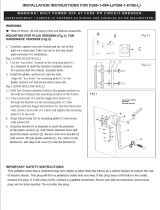
7. Use the silver key to unlock both the control panel and the fascia door (which
conceals the locking mechanism) on the front of the cabinet. Open the fascia
door.
8. Lift the handle under the bill chute to open the front enclosure door. If the
door is locked, see the sidebar on this page for help in unlocking the electronic
or mechanical lock, if applicable.
9. Remove the packing material from inside the vault enclosure and the control
panel area.
10. The accessory box is shipped inside the cabinet enclosure. Open and inspect
the contents. Check the contents against the enclosed packing list and report
any missing parts to Triton.
11. Unbolt the ATM from the shipping pallet. Walk the ATM off of the pallet
using caution. The ATM is heavy.
UNPACK ATM
Combination Locks
Mechanical Lock: There
are two marks on the dial
ring. The index mark at the
top of the dial is used for
opening the lock. A revolu-
tion is counted each time the
selected number is aligned
with the opening index.
Locks are shipped on a fac-
tory setting of ‘50’. To un-
lock, turn the dial to the left
(counterclockwise) FOUR
(4) turns, stopping on ‘50’.
Then turn the dial to the right
(clockwise) until the bolt is
retracted.
Electronic Lock: The com-
bination of the lock is preset
to 1-2-3-4-5-6. To unlock,
enter the preset combination
and check for proper opera-
tion. After each keypress the
lock will ‘beep’. After the
nal digit has been entered,
the lock will beep twice and
the open period begins.
When a valid combination
has been entered, the opera-
tor will have approximately
3 seconds to open the lock.
To open the lock, turn the
outer ring of the dial to the
right (clockwise). After the
lock is opened, the vault
door may be opened.
15
ARGO G60 INSTALLATION MANUAL
Mark the location of the cabinet mounting holes on the concrete oor. This is accomplished as described below:
1. Move the ATM to the location where it will be installed.
Open the cabinet vault door at least 90° to improve access. Locate the four (4) anchor-bolt holes in the
bottom of the cabinet (each corner). Use a felt-tip pen or other marker to carefully mark the center of each
of the four corner holes on the oor; these marks will serve as guides for the anchor bolt holes that will be
drilled in the next step. Move the ATM aside to provide clear access to the mounting hole marks. Center
punch each mark to help align the drill bit.
2. Use a 1/4” [6 mm] diameter carbide-tipped
masonry bit to drill four pilot holes at the drilling
points marked in the previous step. Drill the pilot
holes approximately 1/2” [12 mm] deep into the
oor. These holes will help guide the masonry
bit that will be used to drill the anchor-bolt holes
in the next step.
Mark/Drill Mounting Holes
5. Use a portable vacuum cleaner to remove any
dust or debris that may have fallen into the holes
during the drilling process.
4. Hole Diameter: Ensure the holes drilled are not too large in diameter. Test t the anchor bolts by hand.
They should require hammering, NOT NOW, and not fall into the hole. Its easier to drill the holes larger
now if necessary, than have to move the cabinet and redrill later because they are too big. DO NOT be
tempted to install the anchors now. It is VERY dif cult to position the terminal onto the anchors because
of the weight.
3. Standard anchors: Use a 1/2” [13mm] diameter carbide-tipped masonry bit to drill four holes at least
2-3/4” [70mm] deep into the oor. Be sure to take into account the depth of any oor covering, such as
tile or vinyl when gauging the depth of the anchor holes. Make sure the holes are drilled at least 2- 3/4”
[70mm] into the concrete oor. (See Install Standard Anchors/Bolt ATM to Floor on next page.)
16
ARGO G60 INSTALLATION MANUAL
INSTALL STANDARD ANCHORS/
B
OLT ATM TO FLOOR
LOCKING NUT
FLAT WASHER
ARGO ATM BASE
ANCHOR BOLT
MOUNTING NUT
Anchor bolt installation illustration
SLAB
Anchor Bolt
1. Ensure the mounting location is free of all debris that might cause the
cabinet to not be level. Use blower or vaccuum to remove any dust or
particles.
2. Move the ATM into position for mounting by aligning the base over the
four holes drilled in the previous procedure.
3. Place an anchor bolt through the cabinet base and into one of the
mounting holes. Use a ball peen hammer to tap the bolt completely into
the hole.
IMPORTANT: If the anchor bolt “falls” into the hole without being
tapped in, the hole is too large! Move the mounting hole pattern and
redrill using smaller holes as necessary to achieve a snug t.
4. Place a at washer on the anchor bolt followed by a 1/2” (13mm) nut.
Do not tighten fully, allow for leveling.
5. Repeat Steps 3 and 4 for the remaining anchor bolts.
17
ARGO G60 INSTALLATION MANUAL
6. Ensure the cabinet is as level as possible given the oor conditions. Use a bubble level to verify this. If
a bubble-level is not available, the cabinet can be “rocked” gently from front-to-back and side-to-side to
check the need for leveling.
7. Use a torque wrench and 3/4” [19mm] socket to tighten each nut to 60 foot-pounds (required to establish
the maximum pull-out strength of the anchors). If a torque wrench is not available, use a ratchet wrench
and 3/4” [19mm] socket to tighten the nuts three full turns beyond hand tight. DO NOT overtighten.
8. Once the nuts are tightened as speci ed in Step 7, install a second nut on each bolt, to act as a jam nut,
and tighten down rmly.
Use anchor bolt in each mounting hole
Hammer bolts snuggly into drilled holes
NOTE: Before you start, unlock and open the control panel. Verify that the power
switch on the unit’s power supply is in the OFF (0) position. Close the control panel.
Power Outlet Accessibility
Whether you are installing a new AC socket outlet or plan to use an existing outlet to supply power to the
ATM, make sure the following requirements are met:
1. The outlet is located near the equipment. Extension cords are not recommended.
2. AC power for the terminal should come from a dedicated source with an isolated ground. The ATM
is designed to work on an IT (Isolated-Terra) type power system having phase-to-phase voltage not
exceeding 120 or 240 volts.
3. The outlet is easily accessible and will not be blocked once the equipment is installed and anchored.
ROUTE AC POWER AND COMMUNICATION CABLE
18
ARGO G60 INSTALLATION MANUAL
1. Route the AC power cord and the phone (or Cat-5) cable
through either the main or alternate cable access hole at
rear corner of unit (as applicable).
2. Connect the AC power cord and communication cable to
their respective facility outlets.
3. Secure/plug the unused access hole with the grommet or
plug provided.
4. Install the security bracket. This new feature introduced
with the ARGO G60 prevents both people and rodents
from accessing the dispenser and internal wiring through
the holes at the bottom of the cabinet. The bracket and four
(4) nuts are found packaged in the accessory bag that is
shipped with the ARGO G60.
Fit the bracket on the xed bolts, then use an 11/32” driver
to tighten the nuts.
This unit may be equipped with more than one power cord.
Disconnect All Power Cords prior to Servicing!
For continued fault protection, follow the correct voltage and current ratings when replacing any fuses.
Route wiring and communication
harnesses through openings in
bottom rear of cabinet and to
power supply.
The ARGO G60 unit has an additonal security feature with the
additon of a special bracket between the upper and lower cabinets
to secure cables and wiring running between the cabinets. This is
already installed on the ARGO G60 from the factory. One must
have access to both the upper and lower cabinets in order to add or
remove cables/wiring. The bracket has a top screw and three xed
bolts underneath. Unscrew the screw and three nuts to release the
bracket.
Attach security bracket to lower left
corner of cablinet as shown.
19
ARGO G60 INSTALLATION MANUAL
POWER SUPPLY CORD
SPECIFICATIONS
For European applications, the power supply cord must conform to the following:
1. Two-conductor with Physical Earth (PE) ground.
2. IEC 320 molded connector on one end and molded plug on the other end.
3. Certi ed for country of installation.
4. Rated minimum H05VV-F with minimum 0.75 mm2 (except where speci c countries
require 1.0 mm2) conductors.
5. Maximum length: 3 meters.
REFER TO THE USER MANUAL AND CONFIGURATION MANUAL FOR
OPERATIONAL INSTRUCTIONS.
NOTE: IT MAY TAKE UP TO 30 SECONDS FOR THE DISPLAY TO
ILLUMINATE, AND ANOTHER 15 SECONDS FOR THE OPERATING
SYSTEM TO LOAD.
APPENDIX A
SOFTWARE LICENSE AGREEMENT
COMPLIANCE / EMISSION STATEMENTS
  • Page 1 1
  • Page 2 2
  • Page 3 3
  • Page 4 4
  • Page 5 5
  • Page 6 6
  • Page 7 7
  • Page 8 8
  • Page 9 9
  • Page 10 10
  • Page 11 11
  • Page 12 12
  • Page 13 13
  • Page 14 14
  • Page 15 15
  • Page 16 16
  • Page 17 17
  • Page 18 18
  • Page 19 19
  • Page 20 20
  • Page 21 21
  • Page 22 22
  • Page 23 23
  • Page 24 24
  • Page 25 25
  • Page 26 26
  • Page 27 27
  • Page 28 28
  • Page 29 29
  • Page 30 30
  • Page 31 31

Triton Systems Argo Installation guide

Type
Installation guide

Triton Systems Argo is an automated teller machine (ATM) designed for indoor use, offering secure and easy financial transactions. It features a user-friendly interface, allowing customers to conveniently withdraw cash, check balances, make deposits, and transfer funds. With its compact design, the Argo ATM can be easily integrated into various indoor locations, providing financial accessibility to customers in retail stores, banks, airports, and other public spaces.

Ask a question and I''ll find the answer in the document

Finding information in a document is now easier with AI