Page is loading ...

/
WARNING
— This document supersedes all other information provided by Triton for ATM Installation for acces-
sibility.
— Information provided in these guidelines is based on federal regulations. Customers should verify
federal regulations have not been amended. Each state and/or province may also have accessibility
codes. These codes may be more restrictive than the federal guidelines. Please verify with the state
and/or province prior to installation. For state contact information, call the ADA (Americans with
Disabilities Act) information line at 1-800-514-0301 (or 1-800-514-0383 for TTY).
— For countries other than the U.S., please use the guidelines for accessibility in country of ATM
installation.
— A complete copy of the ADAAG referred to in this document can be found at
http://www.access-board.gov. Included in this document are the ADA guidelines specically relat-
ing to ATMs. For additional information on oor surfaces and other ADA requirements, please see
complete specication.
e ADA standards are issued by the Department of Justice (DOJ) and the Department of Transportation (DOT)
and apply to facilities covered by the ADA in new construction and alterations. DOJ standards apply to all facili-
ties covered by the ADA, except public transportation facilities, which are subject to DOT standards. Both stan-
dards are very similar and are closely based on the Board’s ADA Accessibility Guidelines (ADAAG). However,
each contains a few unique provisions and customers are encouraged to research the complete ADAAG before
ATM installation.
Existing Facilities
e ADA guidelines cover new construction and planned alterations, and generally do not apply to existing
facilities except where altered. Facilities built or altered according to earlier versions of the ADA standards will
not necessarily have to meet updated version except where they are subsequently altered or renovated. e DOJ,
which regulates requirements for existing facilities under the ADA, intends to address coverage of facilities built
or altered according to the original ADA standards in its rule making to update the standards. It will also address
facilities retrotted under ADA provisions for existing facilities, such as the requirement for barrier removal
in places of public accommodation. With respect to ABA (Architectural Barriers Act) facilities, the Board has
claried in the guidelines that facilities built to earlier ABA standards are subject to the new requirements only in
relation to planned alterations. Please check the ADA website for current guidelines.
WARNING
is document is not meant to be a comprehensive representation of ADA guidelines, and focuses largely on
clear oor space requirements when installing an ATM. Additional steps may need to be taken to ensure your
location is fully ADA compliant.
3.5 Clear Floors and Ground Space

305.2 Floor or Ground Surfaces. Floor or ground surfaces of a clear oor or ground space shall comply with
302. Changes in level are not permitted.
EXCEPTION: Slopes not steeper than 1:48 shall be permitted.
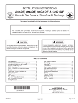
305.3 Size. e clear oor or ground space shall be 30 inches (760 mm) minimum by 48 inches (1220 mm) min-
imum.
48 in. min
1220 mm
30 in. min
760 mm
Figure 305.3 Clear Floor or Ground Space
305.4 Knee and Toe Clearance. Unless otherwise specied, clear oor or ground space shall be permitted to
include knee and toe clearance complying with 306.
305.5 Position. Unless otherwise specied, clear oor or ground space shall be positioned for either forward or
parallel approach to an element. For a forward approach to an element, a clear oor or ground space, 30 inch-
es by 48 inches (760 mm by 1220 mm) minimum, is shown with the shorter dimension parallel to the wall or
element. For a parallel approach to an element, a clear oor or ground space, 30 inches by 48 inches (760 mm by
1220 mm) minimum, is shown with the longer dimension parallel to the wall or element.
48 in. min
1220 mm
30 in. min
760 mm
(a) forward
48 in. min
1220 mm
30 in. min
760 mm
(b) parallel
Figure 305.5 Position of Clear Floor or Ground Space

305.6 Approach. One full unobstructed side of the clear oor or ground space shall adjoin an accessible route or
adjoin another clear oor or ground space.
305.7 Maneuvering Clearance. Where a clear oor or ground space is located in an alcove or otherwise con-
ned on all or part of three sides, additional maneuvering clearance shall be provided in accordance with 305.7.1
and 305.7.2.
305.7.1 Forward Approach. Alcoves shall be 36 inches (915 mm)wide minimum where the depth exceeds 24
inches (610 mm). For a forward approach, if the depth of the alcove is greater than 24 inches (610 mm), the
clear oor or ground space within the alcove must be 36 inches (915 mm) wide minimum.
305.7.2 Parallel Approach. Alcoves shall be 60 inches (1525 mm) wide minimum where the depth exceeds 15
inches (380 mm). For a parallel approach, if the depth of the alcove is greater than 15 inches (380 mm), then the
length of the clear oor or ground space within the alcove must be 60 inches (1525 mm) minimum.
X > 24
610 mm
36 in. min
915 mm
X > 24
610 mm
380 mm
X > 15
Figure 305.7.1 Maneuvering
Clearance in an Alcove, Forward
Approach
Figure 305.7.2 Maneuvering
Clearance in an Alcove, Parallel
Approach
308. Reach Ranges.
308.2 Forward Reach.
308.2.1 Unobstructed. Where a forward reach is unobstructed, the high forward reach shall be 48 inches (1220
mm) maximum, and the low forward reach shall be 15 inches (380 mm) minimum above the nish oor or
ground.

15 in. min
380 mm
48 in. max
1220 mm
Figure 308.2.1 Unobstructed Forward Reach
3.8.2.2 Unobstructed High Reach. Where a high forward reach is over an obstruction, the clear oor space shall
extend beneath the element for a distance not less than the required reach depth over the obstruction. e high
forward reach shall be 48 inches (1220 mm) maximum where reach depth is 20 inches (510 mm), the high for-
ward reach shall be 44 inches (1120 mm) maximum and the reach depth shall be 25 inches (635 mm) maximum.
48 in. max
1220 mm
>20 - 25 in. max
510 - 635 mm
(a)
20 in. max
510 mm
44 in. max
1118 mm
(b)
Figure 308.2.2 Obstructed High Forward Reach
3.8.3 Side Reach.
308.3.1 Unobstructed. Where a clear oor or ground space allows a parallel approach to an element and the side
reach is unobstructed, the high side reach shall be 48 inches (1220 mm) maximum and the low side reach shall
be 15 inches (380 mm) minimum above the nish oor or ground.

Exceptions:
1. An obstruction shall be permitted
between the clear oor or ground space
and the element where the depth of
the obstruction is 10 inches (255 mm)
maximum.
2. Operable parts of fuel dispensers
shall be permitted to be 54 inches (1370
mm) maximum measured from the
surface of the vehicular way where fuel
dispensers are installed on existing
curbs.
48 in. max
1220 mm
15 in. min
380 mm
10 in. max
255 mm
Figure 308.3.1 Unobstructed Side Reach
308.3.2 Obstructed High Reach. Where a clear oor or ground space allows a parallel approach to an element
and the high side reach is over an obstruction, the height of the obstruction shall be 34 inches (865 mm) max-
imum and the depth of the obstruction shall be 24 inches (610 mm) maximum. e high side reach shall be 48
inches (1220 mm) maximum for a reach depth of 10 inches (255 mm) maximum. Where the reach depth ex-
ceeds 10 inches (255 mm), the high side reach shall be 46 inches (1170 mm) maximum for a reach depth of 24
inches (610 mm) maximum.
48 in. max
1220 mm
34 in. max
865 mm
10 in. max
255 mm
(a)
46 in. max
1170 mm
34 in. max
865 mm
(b)
< 10 - 24 in. max
255 - 610 mm
Figure 3.8.3.2 Obstructed High Side Reach
4.2.3 Wheelchair Turning Space. e space required for a wheelchair to make a 360-degree turn is a clear oor
space of 60 inches (1525 mm). For a T-shaped turn, the required clear oor space is 60 inches (1525 mm) by 36
inches (915 mm) as illustrated below.

4.2.3a Wheelchair Turning
Space for a 360° Turn
4.2.3b Wheelchair Turning
Space for a 180° Turn
60 in. min
1525 mm
60 in. min
1525 mm
60 in. min
1525 mm
60 in. min
1525 mm
36 in. min
915 mm
4.2.4 Clear Floor or Ground Space for Wheelchairs.
4.2.4.1 Size and Approach. e minimum clear oor or ground space required to accommodate a single, sta-
tionary wheelchair and occupant is 30 inches by 48 inches (760 mm by 1220 mm). e minimum clear oor
or ground space for wheelchairs may be positioned for forward or parallel approach to an object. Clear oor or
ground space for wheelchairs may be part of the knee space required under some objects.
48 in. min
1220 mm
30 in. min
760 mm
4.2.4.1a forward approach
48 in. min
1220 mm
30 in. min
760 mm
4.2.4.1b parallel approach
4.2.4.2 Relationship Maneuvering Clearance to Wheelchair Spaces. One full unobstructed side of the clear

ground or oor space for a wheel chair shall adjoin or overlap an accessible route or adjoin another wheelchair
clear oor space. If a clear oor space is located in an alcove or otherwise conned on all or part of three sides,
additional maneuvering clearances shall be provided.
760 mm
1220 mm
30 in.
X
48 in.
**Note**
X < 24 in. (610 mm)
760 mm
910 mm
150 mm
30 in.
36 in.
6 in.
X
**Note**
X > 24 in. (610 mm) then an additional 6 in.
(150 mm) shall be provided as shown.
4.2.4.2 a For a front approach, where the
depth of the alcove is equal or less than 24
inches (610 mm), the required clear oor
space is 30 inches by 48 inches (760 mm by
1220 mm).
4.2.4.2b For a front approach, where the
depth of the alcove is greater than 24 inches
(610 mm), then in addition to the 30-inch
(760 mm) width, a maneuvering clearance of
6 inches (150 mm) in width is required.
48 in.
30 in.
1220 mm
760 mm
X
**Note**
X < 15 in. (380 mm)
4.2.4.2c For a side approach, where the depth of the
alcove is equal to or less than 15 inches (380 mm), the
required clear oor space is 30 inches by 48 inches
(760 mm by 1220 mm).
48 in.
60 in.
12 in.
1220 mm
1525 mm
305 mm
X
**Note**
X > 15 in. (380 mm), then an additional maneuvering
clearance of 12 in. (305 mm) shall be provided as shown.
4.2.4.2d For a side approach, where the depth of the alcove
is greater than 15 inches (380 mm), then in addition to
the 48-inch (1220 mm) length, an additional maneuvering
clearance of 12 in. (350 mm) is required.

4.34 Automated Teller Machines.
4.34.1 General. Each automated teller machine required to be accessible by 4.1.3 shall be on an accessible route
and shall comply with 4.34.
4.34.2 Clear Floor Space. e automated teller machine shall be located so that clear oor space complying with
4.2.4 is provided to allow a person using a wheelchair to make a forward approach, a parallel approach, or both,
to the machine.
4.34.3 Reach Ranges.
(1) Forward Approach Only. If only a forward approach is possible, operable parts of all controls shall be
placed within the forward reach range specied in 4.2.5.
(2) Parallel Approach Only. If only a parallel approach is possible, operable parts of controls shall be
placed as follows:
(a) Reach Depth Not More an 10 in (255 mm). Where the reach depth to the operable parts of all
controls as measured from the vertical plane perpendicular to the edge of the unobstructed clear oor
space at the farthest protrusion of the automated teller machine or surround is not more than 10 in
(255 mm), the maximum height above the nished oor or grade shall be 54 in (1370 mm).
(b) Reach Depth More an 10 in (255 mm). Where the reach depth to the operable parts of any
control as measured from the vertical plane perpendicular to the edge of the unobstructed clear oor
space at the farthest protrusion of the automated teller machine or surround is more than 10 in
(255 mm), the maximum height above the nished oor or grade shall be as follows:
Reach Depth Maximum Height
10 in. 255 mm 54 in. 1370 mm
11 in. 280 mm 53.5 in. 1360 mm
12 in. 305 mm 53 in. 1345 mm
13 in. 330 mm 52.5 in. 1335 mm
14 in. 355 mm 51.5 in. 1310 mm
15 in. 380 mm 51 in. 1295 mm
16 in. 405 mm 50.5 in. 1285 mm
17 in. 430 mm 50 in. 1270 mm
18 in. 455 mm 49.5 in. 1255 mm
19 in. 485 mm 49 in. 1245 mm
20 in. 510 mm 48.5 in. 1230 mm
21 in. 535 mm 47.5 in. 1205 mm
22 in. 560 mm 47 in. 1195 mm
23 in. 585 mm 46.5 in. 1180 mm
24 in. 610 mm 46 in. 1170 mm
(3) Forward and Parallel Approach. If both a forward and parallel approach are possible, operable
parts of controls shall be placed within at least one of the reach ranges in paragraph (1) or (2) of this

section.
(4) Bins. Where bins are provided for envelopes, waste paper, or other purposes, at least one of each
type provided shall comply with the applicable reach ranges in paragraph (1), (2), or (3) of this section.
Exception:
Where a function can be performed in a substantially equivalent manner by using an alternate control,
only one of the controls needed to perform that function is required to comply with this section. If the
controls are identied by tactile markings, such markings shall be provided on both controls.
4.34.4 Controls. Controls for user activation shall comply with 4.74.4.
4.34.5 Equipment for Persons with Vision Impairments. Instructions and all information for use shall be made
accessible to and independently usable by persons with vision impairments.
(20) Where Automated Teller Machines (ATMs) are provided, each ATM shall comply with the requirements in
4.34 except where two or more are provided at a location, then only one ATM must comply.
Exception:
Drive-up only ATMs are not required to comply with 4.27 Controls and Operating Mechanisms or 4.34.4
Reach Ranges.
/