Page is loading ...

(en-US)
JACK STAND INSTRUCTIONS

2
About OTC
OTC was founded in
1925 in Owatonna,
Minnesota as the
Owatonna Tool Company.
What started as a small specialty tool
manufacturer has grown into a global provider of
specialty tools to nearly every technician, mechanic, independent
repair shop, automotive dealership and tractor manufacturer.
OTC continues to operate its design, engineering, manufacturing
and distribution facility in Owatonna, Minnesota. The current
plant opened in the late 1950s, employing hundreds of tool
specialists who forge, heat treat, coat and assemble the OTC
tools you trust.
Since its founding, OTC has always stood for quality and
ingenuity, creating reliable solutions that make repairing vehicles
and equipment easier.
The OTC tool you purchased today has been crafted to exacting
specifications to provide you with the tool you need, when you
need it, for life. All OTC tools are covered by a lifetime warranty,
ensuring years of worry-free use. OTC tools are key to getting
the job done.
Thank you for supporting OTC. Your purchase drives the
research, innovation, engineering and development of new tools
and equipment.
Looking for more OTC tools? Visit www.otctools.com and
subscribe to our e-newsletter for new tools, promotions and
OTC news.

JACK STAND INSTRUCTIONS
3
All Automotive Stands
• Study, understand, and follow all instructions before
operating these devices.
• Wear ANSI Z87.1 and OSHA approved eye protection.
• Do not exceed rated capacity.
• Use only on a hard, level surface capable of supporting
the load.
• Center load on saddle.
• Locate saddles at vehicle manufacturer’s designated
support points.
• No alterations shall be made to these products.
• Failure to heed these markings may result in personal
injury/property damage.
Jack Stands
• Use only as an identical pair.
• Maximum load capacity per identical pair shall not
exceed the rated capacity of the individual stand.
• Use stands to support one end of a vehicle only. These
stands are not to be used to simultaneously support
both ends of a vehicle.
All High Reach Stands
• Only attachments, restraints, or adapters supplied by
the manufacturer shall be used.
• Do not enter the vehicle or start the engine while the
vehicle is supported on stands.
Supplementary Support Stands
• Do not use these stands to support a vehicle.
• Use stands in pairs to stabilize the vehicle before
starting repairs.
Safety Information
(Continued on next page.)

4
• Use a minimum of four stands to support and stabilize a
vehicle, and a minimum of two additional stands for each axle
assembly, before starting repairs.
• The vehicle shall be raised only once to place vehicle support
stands under the entire vehicle.
• Ensure stands are stable and vehicle is balanced before
lowering the vehicle onto stands.
• Carefully lower the vehicle onto all stands simultaneously.
• Do not apply horizontal forces or large torque loads to vehicle
while the vehicle is supported on stands.
Under Hoist Auxiliary Stands
• These stands are intended to provide partial support of
vehicle components during removal and installation.
• Adequately support the vehicle before starting repairs.
• Do not use to support or stabilize vehicle.
Safety Information
Shop Equipment Recommendations
As with any tool or piece of equipment, it is highly recommended
to follow all applicable safety guidelines pertaining to its
use. Appropriate Personal Protective Equipment as outlined
by OSHA and ANSI standards, include (but are not limited
to) safety glasses or face shields, protective gloves, hearing
protection and reinforced (or safety toe) footwear. While using
tools and equipment, ensure that you are clear of any moving
parts or potential pinch points. To ensure the continued safe
operation of tools and equipment, always follow manufacturer’s
recommended cleaning and lubrication schedules to prevent
foreign material build up.
(continued)

JACK STAND INSTRUCTIONS
5
The warnings and instructions discussed
in this manual cannot cover every situation,
Always work with a focus on safety.
• Inspect paint for chipping, runs, misses or overspray.
• Inspect weldments for breaks or spatter.
Inspection Instructions
Upon delivery, inspect carton for unnecessary damage. Where
appropriate, address carton damage with carrier.
Remove jack stand from carton and assemble following the
instructions in this manual. Inspect jack stand for the following:
If your inspection reveals any issue with the jack stand’s
appearance or performance, please contact the
OTC Technical Service Hotline at 800-533-6127
to report an issue and file a warranty claim.
If possible, retain the original carton for return shipping.
A replacement will be sent and a call tag will be issued
to pick up the jack in question.
Replacement Parts
To ensure the safety features of your jack stands are not
compromised, OTC oers a limited selection of replacement parts.
Replacement part information for your model can be found by
visiting www.otctools.com.
Contact our tech service team at 800-533-6127 for assistance.

6
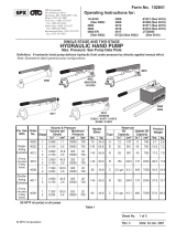
Pin Style Stand
1. Install the support tube into the
base, aligning the hole through
the base with the holes at the
bottom of the tube.
2. Install the base bolt through
the base and support tube,
thread the nut onto the end of
the bolt.
Saddle
Column
Locking Pin
& Chain
Base Bolt
Base
Support
Tube
Assembly Instructions
Ratchet and Pawl Style Stand
1. Install the ratchet bar into the
frame with the ratchet portion
of the bar aligned with the
locking pawl (stopper).
2. Move the ratchet bar to its
lowest position by raising the
locking handle (which releases
the stopper) and guiding the
bar downward.
3. Use a hammer and punch
to tap the tab into position
(almost touching the ratchet
bar). When the ratchet bar is
extended, the tab will catch
on a lip, preventing over-
extension of the ratchet bar.
Saddle
Frame
Locking
Handle
Ratchet
Bar
Tab
Figure 1
Figure 2

JACK STAND INSTRUCTIONS
7
High Reach
Under Hoist Auxiliary Stand
1. Attach post support to base.
2. Insert post into post
support, aligning holes.
Secure with support tube
hardware (clevis pin, [2]
washers, and cotter pin.)
3. Screw adjusting handle
onto threaded rod until
tight against saddle pad.
4. Place bearing assembly
onto threaded rod and set
rod into post.
Under Hoist Auxiliary Stand
with Pedal
1. Complete the above steps 1-4
and then, attach pedal to post
support, and secure with clevis
pin, (2) washers, and cotter pin.
Figure 3
Post Support
Hardware
Bearing
Assembly
Base
Post
Adjusting
Handle
Saddle
Post
Support
Foot Pedal
(See instructions
below.)

8
High Reach
Supplementary Support Stands
Tube Assembly
1. Use bolts to attach saddle
to saddle base.
2. Slide screw rod into outer
tube. Install bearing on
outer tube.
3. Install handle and saddle
base onto screw rod and
secure with a bolt.
Stand Assembly
1. Loosely attach braces to
legs using bolts, washers,
and nuts provided.
2. Loosely attach tube
brackets to legs using bolts,
washers, and nuts provided.
3. Loosely attach tube plate to
tube brackets using bolts,
washers, and nuts provided.
4. Slide outer tube assembly
through bushing base and
tube plate. Use detent pin
and chain assembly to lock
tube in any position.
5. Securely tighten bolts and
nuts.
Assembly Instructions
(continued)
Figure 4
Leg
Outer
Tube
Handle
Bearing
Assembly
Saddle
Base
Screw
Rod
Saddle
Detent
Pin
Bushing
Base
Brace
Tube
Bracket
Tube
Plate

JACK STAND INSTRUCTIONS
9
1. Before every use – INSPECT the jack stand for performance
issues. Do not use the jack if any quality issue is discovered.
2. Plan the location of the jack stands in pairs on a smooth, hard,
level surface to ensure a balanced load.
3. Position each jack stand so the weight will be exerted on the
center of the saddle.
4. Extend the jack up to the load. Insert pins or lock handles in
place, depending on the model of jack stand.
WARNING: To prevent personal injury and/or
equipment damage, ensure all pins are completely
inserted through support tubes AND saddle
columns and locked in place. Ensure lock handles
are completely engaged in ratchet grooves.
5.
Slowly and carefully lower the load onto the
jack stands.
6. When service work is complete, raise vehicle o of jack stands
with the same equipment that raised the vehicle initially, and
remove stands from under the vehicle.
7. Keep clear of load while lifting and lowering the vehicle.
8. Carefully and slowly lower vehicle onto the ground.
OTC Jack Stands
High Reach
Auxiliary Stands (See Fig. 3)
Operating Instructions
Raise the Load
1. Turn adjusting handle clockwise until saddle
meets load. Continue turning handle or use
pedal to raise load to required height.
Lower the Load
1. Turn adjusting handle counterclockwise.

10
High Reach Supplementary
Support Stands (See Fig. 4)
Raise the Load
WARNING: To prevent personal injury and/
or property damage, do not attempt to remove
the detent pin with a load on the stand.
1. Major adjustments in the height of the stand must be made
before putting a load on the stand. For a major adjustment,
remove the detent pin and raise the outer tube to desired
height. Replace detent pin.
2. Once a load is on the stand, minor adjustments can be made by
turning the adjusting handle clockwise to a desired height.
Lower the Load
1. Turn adjusting handle counterclockwise.
2. For a major adjustments, remove the detent pin and lower the
outer tube to desired height. Replace detent pin.
Operating Instructions
(continued)

JACK STAND INSTRUCTIONS
11
Lifetime Warranty® Effective 4/1/84
THIS WARRANTY IS EXPRESSLY LIMITED
TO ORIGINAL RETAIL BUYERS OF SERVICE
SOLUTIONS U.S. INC.’ OTC BRAND
PRODUCTS OR PARTS (“OTC PRODUCTS”).
THIS WARRANTY IS NOT ASSIGNABLE OR
TRANSFERABLE. SERVICE SOLUTIONS
MAKES NO WARRANTY TO ANYONE ELSE,
INCLUDING OTHER PURCHASERS AND/OR
USERS, AND NONE SHALL BE IMPLIED.
Except as otherwise provided in this warranty, OTC
products are warranted against defects in materials and
workmanship for the life of the OTC Product, meaning that point in time when
the OTC product no longer functions due to normal wear. This warranty does
not apply to electronic products, which are covered by separate warranties.
Nor does this warranty apply to the following items, which may be incorporated
into or sold with OTC Products and which are sold “as-is” with all faults: chains,
batteries, electric motors, knives, and cutter blades. (Electric motors are
warranted by their manufacturers under conditions stated in their warranties).
The sole and exclusive remedy for any OTC Product found to be defective
is repair or replacement, at the option of Service Solutions. If this exclusive
remedy is deemed to have failed of its essential purpose, Service Solutions’
liability shall not exceed the purchase price of the OTC Product. In no event
will Service Solutions be liable for any direct, indirect, special, incidental, or
consequential damages (including lost prot) whether based on warranty,
contract, tort, or any other legal theory.
This warranty does not cover any OTC Product that has been abused, altered,
worn out, contaminated, rusted, heated, ground, damaged due to side loading,
used for a purpose other than that for which it was intended, or used in a
manner inconsistent with Service Solutions/OTC’s instructions regarding
use. The existence of a defect shall be determined by Service Solutions
in accordance with procedures established by Service Solutions. No one is
authorized to make any statement or representation altering the terms of this
warranty.
THIS WARRANTY IS IN LIEU OF ANY OTHER WARRANTY, EXPRESS
OR IMPLIED, INCLUDING ANY WARRANTY OF MERCHANTABILITY OR
FITNESS FOR A PARTICULAR PURPOSE.

655 EISENHOWER DRIVE
OWATONNA, MN 55060 USA
TECH SERVICES 800-533-6127
FAX 800-955-8329
CUSTOMER SERVICE 800-533-6127
FAX 800-283-8665
www.otctools.com
SP04518826 Rev. 1
March 31, 2020 © Bosch Automotive Service Solutions Inc.
/