Page is loading ...

Sheet No.
Issue Date: Rev D, Nov. 18, 2014
© Bosch Automotive Service Solutions LLC
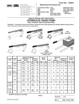
High Lift Transmission Jack
Max. Capacity: 2,000 lbs. at 100-140 psi air
Application: Installation and removal of truck and automobile transmissions
1 of 3
2
3
4
5, 6, 7
89
10 11
12
13
14
See Detail A
For a parts breakdown
of the hydraulic ram,
see sheet 2 of 3.
IMPORTANT: Remove the
shipping oil plug on top of
the air hydraulic foot pump
reservoir, and replace it with the
vented oil plug provided. The
jack will not function correctly if
the shipping plug is left in.
27
25
26
35, 36
33, 31
32 31
17
29, 30, 31
28
16
18
17
19
20
21, 22
22, 23, 24
Detail A
Form No. 106329
Parts List &
Operating Instructions
for: 5078
655 Eisenhower Drive
Owatonna, MN 55060 USA
Phone: (507) 455-7000
Tech. Serv.: (800) 533-6127
Fax: (800) 955-8329
Order Entry: (800) 533-6127
Fax: (800) 283-8665
International Sales: (507) 455-7223
Fax: (507) 455-7063
34

Parts List & Operating Instructions Form No. 106329, Sheet 1 of 3, Back
Description
Item
No.
Part
No.
No.
Req'd
1 12365 4 External Retaining Ring
2 11903 1 Retaining Ring
3 54626 1 Main Base Assembly
4 19802 3 Abrasive Roll
5 10559 16 Hex Hd. Cap Screw
6 10257 16 Washer (for 5/16" bolt)
7 10201 16 Hex Nut (5/16-18)
8 16002 4 Caster
9 314726 1 Hydraulic Hose (30 in.)
10 11628 1 Straight Fitting
11 66226 1 Air Hydraulic Foot Pump
12 46963 1 Decal
13 314743 1 Warning Decal
14 223514 1 Decal
16 15997 1 Cotterless Hitch Pin
17 222237 2 Pivot Shaft
18 222238 1 Pivot Shaft
19 314152 2 Threaded Rod
20 222239 1 Hex Hd. Cap Screw
21 10093 1 Hex Hd. Cap Screw
22 15013 3 Hex Locknut (1/2-13)
23 314748 1 Strap
24 10089 1 Hex Hd. Cap Screw
25 314733 1 Front Support Bracket
26 314734 1 Mounting Plate
27 314730 1 Back Support Bracket
28 440400 1 Pivot Linkage Assembly
29 222235 2 Slotted Hex Nut
30 214021 4 Thrust Bearing Washer
31 10895 4 Roll Pin
32 222236 1 Pivot Shaft
33 314735 2 Handle
34 314154 1 Pivot
35 12004 3 Washer (for 1/2" bolt)
36 10079 3 Hex Hd. Cap Screw

Sheet No.
Issue Date: Rev D, Nov. 18, 2014
© Bosch Automotive Service Solutions LLC
2 of 3
Parts List & Operating Instructions Form No. 106329
5
6
7
8
1
2
3
4
Refer to any operating instructions included with the product for detailed information about
operation, testing, disassembly, reassembly, and preventive maintenance.
Items found in this parts list have been carefully tested and selected by OTC. Therefore:
Use only OTC replacement parts!
Additional questions can be directed to our Technical Services Dept. at 1-800-533-6127.
Item
No.
Part
No.
No.
Req'd Description
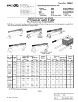
1 *15130 1 Plug
2 *223492 1 Wear Ring (2" O.D.)
3 63340 1 Packing Gland
4 314728 1 Displacement Cylinder
5 440685 1 Cylinder Rod
6 *19591 1 Rod Wiper
7 *223490 1 U-cup Seal
8 *223491 2 Wear Ring (1.875" O.D.)
9 *14848 1 O-ring
Items marked with an asterisk (*) are included in
Seal Repair Kit No. 300717.
Cylinder Assembly
9

Safety Precautions
Caution: To prevent personal injury and damage to equipment,
• Read, understand, and follow all safety precautions and operating instructions.
• Wear eye protection that meets the requirements of ANSI Z87.1 and OSHA.
• A load must never exceed the rated lifting capacity of the jack.
• Do not lift or support the vehicle with this jack. Place support stands under the
vehicle before starting repairs.
• Use the jack on a hard, level surface.
• Center the load on the jack saddle. Off-center loads can damage the seals in the
ram and cause jack failure.
• Never move the jack with a load any higher off the ground than necessary. Slowly
and carefully move the jack around corners because the load could tip. Stay clear
of a lifted load.
• Lower the jack slowly and carefully while watching the position of the load.
• Do not modify the jack or use adapters unless approved or supplied by OTC.
• Use only anti-wear hydraulic jack oil with a 215 SUS viscosity rating at 100° F. The
use of alcohol, hydraulic brake uid, or transmission oil could damage seals and
result in jack failure.
This guide cannot cover every situation, so always do the job with safety rst.
Setup Instructions
(Item numbers refer to the parts list.)
1. Remove transmission jack from the pallet. Attach casters (Item No. 8) using hardware (5, 6, & 7) provided.
2.Thetransmissionsupportbrackets(25&27)tAllison500and600Seriestransmissions.
A. Use fasteners (35 & 36) to loosely assemble the brackets to the mounting plate. See Detail A.
B.Adjustthebracketstotthetransmissionpansotheloadiscenteredonthejack.
C. Tighten the fasteners assembled in Step A above.
3. Remove the shipping plug from the air hydraulic foot pump. Replace the shipping plug with the vented
plug provided.
4.Thereservoirtubeisshippedlledwithhydraulicoil.Beforeusingthejackforthersttime,pressthe
release pedal to open the release valve, and operate the foot pump eight full strokes to distribute the oil.
Operating Instructions
1. Refer to vehicle's service manual and use the recommended service procedure for removal of the component.
2. Position the jack under the vehicle.
3. Raise the jack by operating the foot pump until the saddle touches the component.
4.Adjustthesupportbracketstotthecomponent.
5. Use the tilt crank to align the saddle with the component.
6. Finish raising the jack to the component. Secure the strap assembly around the component.
Maintenance
1.Useonlyanti-wearhydraulicjackoil.Theuseofalcohol,hydraulicbrakeuid,ortransmissionoilcould
damage the seals in the cylinder and result in jack failure.
2.Checktheoillevelperiodically:lowerthejacktoitslowestposition;removethellerplug;addhydraulic
oil(215SUSviscosityat100°F)untiltheoilleveliswithin1/2"ofthellerhole;installthellerplug.
3. Lubricate the foot pump pivot points as needed with SAE 30 motor oil to prevent premature wear.
CAUTION: The greatest single cause of failure in hydraulic units is dirt. Keep the jack clean and well lubricated
to prevent foreign matter from entering the hydraulic system.
Parts List & Operating Instructions Form No. 106329, Sheet 2 of 3, Back

Sheet No.
Issue Date: Rev D, Nov. 18, 2014
© Bosch Automotive Service Solutions LLC
3 of 3
Bleeding Air from the Jack
1. Retract the jack to its lowest position, and loosen the vented oil plug threaded into the top plate of the foot
pump reservoir.
2. Remove the plug (No. 15130, Item No. 1 in the cylinder assembly parts list) from the top of the packing
gland (No. 63340, Item No. 3).
3. Operate the foot pump until the main cylinder is full of oil.
4. Install the plug removed in Step 2.
5. Retract the jack to its lowest position.
6.Fillthefootpumpreservoirwithhydraulicjackoil(215SUSviscosityratingat100°F)tothecorrectuid
level (1/2" from the top).
7. Install the vented oil plug on the foot pump, and inspect for leaks.
Troubleshooting Guide
Repairproceduresmustbeperformedinadirt-freeenvironmentbyqualiedpersonnelwhoarefamiliarwith
this equipment.
Trouble Cause Solution
Unit fails to extend or extends 1.Lowuidlevel 1.Filltocorrectuidlevel.
partially
Incomplete or spongy cylinder 1.Lowuidlevel 1.Filltocorrectuidlevel.
response when foot pedal is 2. Air in system 2. Follow instructions to bleed air from system.
pumped
Abnormal leakage through 1.Lowuidlevel 1.Filltocorrectuidlevel.
unit breather
Unit fails to extend when foot 1. Release valve malfunction 1. Pump foot pedal with release valve open.
pedal is pumped 2. Contamination 2. Disassemble and clean unit.
3. Cylinder packing failure 3. Install repair kit.
Cylinder creeps 1. Load exceeds maximum 1. Reduce load.
lifting capacity
2. Release valve is leaking 2. Flush release valve by pumping foot pedal
with release valve open.
Cylinder doesn't retract when 1. Cylinder is binding 1. Disassemble unit; replace defective parts.
release pedal is activated
Cylinder doesn't extend 1. Contamination 1. Disassemble and clean unit.
2. Bad packing 2. Install repair kit.
Cylinder extends when foot pedal 1. Release valve malfunction 1. Flush release valve by pumping foot pedal
is pressed, and retracts as foot with release valve open.
pedal retracts 2. Contamination 2. Disassemble and clean unit.
Parts List & Operating Instructions Form No. 106329
/