Page is loading ...

Sheet No.
Issue Date: Rev. C, January 20, 2015
© Bosch Automotive Service Solutions Inc.
Form No. 572044
Parts List &
Operating Instructions for: 1591B
655 Eisenhower Drive
Owatonna, MN 55060 USA
Phone: (507) 455-7000
Tech. Serv.: (800) 533-6127
Fax: (800) 955-8329
Order Entry: (800) 533-6127
Fax: (800) 283-8665
International Sales: (507) 455-7290
Fax: (507) 455-7063
Portable
Air Lift Jack/Support Stand
Max. Capacity: 10 Tons at 200 PSI
1 of 2
Explanation of Safety Signal Words
The safety signal word designates the degree or level of hazard seriousness.
DANGER: Indicates an imminently hazardous situation which, if not avoided, will result in death or
serious injury.
WARNING: Indicates a potentially hazardous situation which, if not avoided, could result in death or
serious injury.
CAUTION: Indicates a potentially hazardous situation which, if not avoided, may result in minor or
moderate injury.
CAUTION: Used without the safety alert symbol indicates a potentially hazardous situation which, if not
avoided, may result in property damage.
Description:
The 1591B 10-ton capacity
air lift jack can be used as
a lifting device and support
stand when servicing a
vehicle.
It has a height range of
18-3/4 in. (47.63 cm) to
50-1/2 in. (128.27 cm) and
features a 3-position handle
and 8 ft. air hose.

Parts List & Operating Instructions Form No. 572044, Sheet 1 of 2, Back
Safety Precautions
WARNING: To prevent personal injury and / or property damage:
• Read and understand the safety precautions and operating instructions before using
the air lift jack. If the operator cannot read English, operating instructions and safety
precautions must be read and discussed in the operator’s native language.
• Wear eye protection that meets ANSI Z87.1 and OSHA standards.
• Do not modify the air lift jack or use attachments unless approved or supplied by OTC.
• A load must never exceed the maximum capacity of the jack.
• Before lifting a vehicle, release the parking brake, place the gear selector in neutral, and
chock the wheels at the opposite end.
• Use the jack on a hard, level surface.
• Stay clear of a raised load.
• Release pressure SLOWLY.
Operating Instructions
1. Before lifting a vehicle, release the parking brake, place the gear
selector in neutral, and chock the wheels at the opposite end.
2. Pin the lift handle into a preferred position for moving the air lift.
Move the air lift jack into position under the vehicle frame.
3. Raise the lifting saddle and insert the pin into the hole that retains
the saddle closest to the lifting point.
4. Set shop air pressure at 200 psi or less. Connect a shop air hose
to the tting on the jack’s control valve.
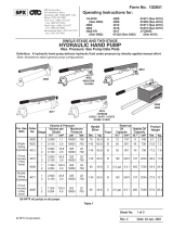
5. Using the control valve lever, apply shop air until the jack saddle
meets the load to be raised. Lifting saddle must cradle the lifting
point by nesting around the frame, bumper, or bed. See Figure 1.
6. Continue applying shop air to raise the load to desired height.
Then insert the second pin into the hole on the piston tube and
SLOWLY release pressure until the load comes to rest on the pin.
7. To lower the load, raise the load until the pin in the piston tube
can be removed. Then SLOWLY lower the load until the lifting
saddle is clear of the load, and remove the pin in the lifting saddle.
Figure 1
Maintenance
CAUTION: Water entering the jack from the air supply or through the top cover plate can collect in
the bottom of the cylinder, and result in rust buildup on the cylinder wall. Drain water out of the jack
on a regular basis by removing the 45° elbow tting at the base of the cylinder, and tilting the jack
until all the water is removed.
1. Lubricate the wheel shafts and center tube as needed with a high quality grease.
2. Inspect the air lift jack before each use. Keep the control valve and ttings clean. Keep the surface of the
lifting saddle clean to ensure sufcient grip during a lift.
3. Periodically check the inlet air lter for debris. Clean or replace the lter when necessary.
Lifting Saddle
Pin
Piston
Tube

Sheet No.
Issue Date: Rev. C, January 20, 2015
© Bosch Automotive Service Solutions Inc.
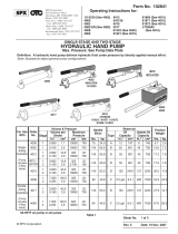
Item Part No.
No. No. Req'd Description
Parts List & Operating Instructions Form No. 572044
2 of 2
1 54425 1 Cover Plate
2 440223 1 Piston Assembly
3 48349 1 Saddle Tube
5 572977 1 Assembly Handle
6 217336 2 Wear Ring Kit
9 571653 1 Body Weldment
14 217164 1 U-cup Seal
15 217175 1 Bearing Strip
18 216296 1 Filter Disc
21 313881 2 Pin
22 48354 1 Extension Tube
Parts List
1
2
3
4
5
6
7
8
9
10
11
12 13 14
15
16
18
19 25
20
24
23
22
21
17

Parts List & Operating Instructions Form No. 572044, Sheet 2 of 2, Back
4 2 Handle Grip
7 6 Hex Nut (5/8-11; torque to 80-110 ft. lbs.)
8 6 Lock Washer (for 5/8 in. bolt)
10 1 Warning Decal
11 2 Cotterless Hitch Pin
12 1 Hex Hd. Cap Screw (1/2-13 x 1-1/4 in. lg.)
13 1 Washer
16 4 Pin
19 1 45° Fitting
20 1 Part Number Decal
24 4 Washer (for 3/4 in. bolt)
Item
No.
No.
Req'd. Description
Hardware Kit No. 572047
17 1 Air Valve / Hose Assembly
Item
No.
No.
Req'd. Description
Valve and Hose Kit No. 564177
23 2 Wheel (6 in. dia.)
25 2 Cotter Pin
Item
No.
No.
Req'd. Description
Wheel Kit No. 564178
Refer to any operating instructions included with the product
for detailed information about operation, testing, disassembly,
reassembly, and preventive maintenance.
Items found in this parts list have been carefully tested and selected
by OTC. Therefore: Use only genuine OTC replacement parts.
Additional questions can be directed to our Technical Service Dept.
Get parts at OTCparts.com
Get parts at OTCparts.com
/