Page is loading ...

Sheet No.
Issue Date: Rev. A Sept. 12, 2013
© Bosch Automotive Service Solutions LLC
Form No. 561942
Parts List &
Operating Instructions
for: 558382
Auxiliary Box Adapter
Maximum Capacity: 227 kg (500 lbs.)
655 Eisenhower Drive
Owatonna, MN 55060 USA
Phone: (507) 455-7000
Tech. Serv.: (800) 533-6127
Fax: (800) 955-8329
Order Entry: (800) 533-6127
Fax: (800) 283-8665
International Sales: (507) 455-7223
Fax: (507) 455-7063
Website: www.otctools.com
1 of 2
Description:
Mounting adapter designed to be
used on a transmission jack mounting
plate for the purpose of removing and
installing the transmission housing
auxiliary box.
Use with:
• OTC No. 5019A, 5078, or 1522A
Transmission Jack for removal and
installation of differential assemblies.
• OTC No. 5130 DriveMaster™
Driveline Lift for removal and
installation of driveline components.
Item Part No.
No. No. Req'd Description
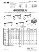
1 569968 1 Plate Assembly (consists of plate & decal)
Parts List
Item
No. Qty. Description
2 2 Carriage Bolt — 1/2-13 x 30.48 mm (1.25 in.)
3 1 Hex Head Screw — 3/8-16 x 50.8 mm (2 in.)
4 1 Stud — .500-13 x 101.6 mm (4 in.)
5 6 Flange Nut — 1/2-13 thread
6 1 Ratchet Strap — 122 cm (4 ft.)
7 1 Support Screw — 95.25 mm (3.75 in.)
Repair Kit No. 569967
4
5
2
3
7
6
Get parts at OTC
parts.com.
This document contains product
parts lists, and information regarding
operation and maintenance. Items
listed in the parts list have been
carefully tested and selected by
OTC. Therefore: Use only OTC
replacement parts.
Product questions can be directed
to the OTC Technical Service
Department at (800) 533-6127.
1

Parts List & Operating Instructions Form No. 561942, Sheet 1 of 2, Back
Safety Precautions
CAUTION: To prevent personal injury and/ or property damage,
• Study, understand, and follow all safety precautions and operating instructions before using
the auxiliary box adapter. If the operator cannot read instructions, operating instructions
and safety precautions must be read and discussed in the operator’s native language.
• Only qualied operators may install, operate, adjust, maintain, clean, repair, inspect, or
transport this auxiliary box adapter.
• Wear eye protection that meets ANSI Z87.1 and OSHA standards.
• Do not exceed the rated capacity of this auxiliary box adapter as stated in this document
and on the warning decal.
• Do not use this auxiliary box adapter for anything other than their intended purpose.
• Use the ratchet strap included to secure the load to the transmission jack.
• No alteration shall be made to this product.
• Inspect the condition of the auxiliary box adapter before each use; do not use if damaged,
altered, or in poor condition.
• Use only those repair parts called out in the parts list in this document. Items found in
the parts list have been carefully tested and selected by OTC. Obtain replacement parts at
OTCparts.com.
Explanation of Safety Signal Words
The safety signal word designates the degree or level of hazard seriousness.
DANGER: Indicates an imminently hazardous situation which, if not avoided, will result in death or
serious injury.
WARNING: Indicates a potentially hazardous situation which, if not avoided, could result in death or
serious injury.
CAUTION: Indicates a potentially hazardous situation which, if not avoided, may result in minor or
moderate injury.
CAUTION: Used without the safety alert symbol indicates a potentially hazardous situation which, if not
avoided, may result in property damage.

Sheet No.
Issue Date: Rev. A Sept. 12, 2013
© Bosch Automotive Service Solutions LLC
Operating Instructions
1. Install the auxiliary box adapter on the
transmission jack mounting plate using the
carriage bolts and ange nuts provided. Tighten
the ange nuts. See Figure 1.
2. Plan the placement of the support screw and
stud to t your application. Figure 1 shows
the support screw and the stud assembled to
the adapter plate in one of several possible
arrangements.
3. Assemble both the support screw and the stud
to the plate with one ange nut above the plate
and one ange nut below the plate. The at
side of each ange nut must rest against the
plate.
4. Thread the lower ange nut on the stud all the
way to the bottom of the threads. This allows
room for adjustment.
5. Remove a bolt from the front of the transmission
auxiliary box.
6. Move the jack under the transmission, aligning
the stud with the hole where the bolt was
removed in the auxiliary box. Insert the bolt
through the stud and into the auxiliary box.
See Figure 2.
Carriage Bolt &
Flange Nut
Support Screw &
(2) Flange Nuts
Stud
Flange
Nuts (2)
Figure 1
Figure 2
Bolt Inserted Through
Stud and Auxiliary Box
Ratchet
Strap
Ratchet Strap
Hooked
Through
Hole in Plate
2 of 2
Parts List & Operating Instructions Form No. 561942

Inspection and Maintenance
CAUTION: To prevent personal injury,
• Only qualied personnel shall perform inspections and repairs to this auxiliary box adapter.
• Before each use, an approved inspector must inspect the auxiliary box adapter for bends, cracks,
dents, elongated holes, or missing hardware. If damage is found, discontinue use.
• Use only those repair parts called out in the parts list in this document. Items found in the parts
list have been carefully tested and selected by OTC. Order replacement parts from OTCparts.com.
Figure 3
Support
Screw
7. Thread the upper ange nut on the support screw
to the bottom of the threads until the support screw
touches the housing. See Figure 3.
8. Install the ratchet strap to secure the auxiliary box
to the transmission jack. See Figure 2. Attach the
hooks on the end of the ratchet strap to the slots
provided in the mounting plate or other suitable
locations.
Operating Instructions contd.
Parts List & Operating Instructions Form No. 561942, Sheet 2 of 2, Back
/