Page is loading ...

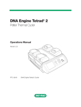
PTC-100
®
Thermal Cycler
Operations Manual
Version 9.0
(applicable to revision 6 instruments only)

PTC-100
®
Thermal Cycler
Operations Manual
Version 9.0
(applicable to revision 6 instruments only)

ii Tech Support: 1-800-4BIORAD • 1-800-424-6723 • www.bio-rad.com
Copyright ©2005, Bio-Rad Laboratories, Incorporated. All rights reserved. Reproduction in any form, either print or electronic,
is prohibited without written permission of Bio-Rad Laboratories, Inc.
Chill-out, Concord, Hard-Shell, Hot Bonnet, Microseal, Multiplate, PTC-100, and Slide Griddle are trademarks belonging to
Bio-Rad Laboratories, Inc.
NOTICE TO PURCHASER
Purchase of this instrument, Serial No. ____________, conveys a limited non-transferable immunity from suit for the purchaser’s
own internal research and development and for use in applied fields other than Human In Vitro Diagnostics under one or more
of U.S. Patents Nos. 5,656,493, 5,333,675, 5,475,610 (claims 1, 44, 158, 160-163 and 167 only), and 6,703,236 (claims 1-7
only), or corresponding claims in their non-U.S. counterparts, owned by Applera Corporation. No right is conveyed expressly,
by implication or by estoppel under any other patent claim, such as claims to apparatus, reagents, kits, or methods such as 5’
nuclease methods. Further information on purchasing licenses may be obtained by contacting the Director of Licensing,
Applied Biosystems, 850 Lincoln Centre Drive, Foster City, California 94404, USA.
07512 rev F

Tech Support: 1-800-4BIORAD • 1-800-424-6723 • www.bio-rad.com iii
Explanation of Symbols . . . . . . . . . . . . . . . . . . . . . . . . . . . . . . . . . . . . . . . . . . . . . . . . . . .iv
Safety Warnings . . . . . . . . . . . . . . . . . . . . . . . . . . . . . . . . . . . . . . . . . . . . . . . . . . . . . . . . .iv
Safe Use Guidelines . . . . . . . . . . . . . . . . . . . . . . . . . . . . . . . . . . . . . . . . . . . . . . . . . . . . . . .v
Electromagnetic Interference . . . . . . . . . . . . . . . . . . . . . . . . . . . . . . . . . . . . . . . . . . . . . . .v
FCC Warning . . . . . . . . . . . . . . . . . . . . . . . . . . . . . . . . . . . . . . . . . . . . . . . . . . . . . . . . . . . . .v
Documentation Conventions . . . . . . . . . . . . . . . . . . . . . . . . . . . . . . . . . . . . . . . . . . . . . . .vi
1. Introduction . . . . . . . . . . . . . . . . . . . . . . . . . . . . . . . . . . . . . . . . . . . . . . . . . . . . . . . . . .1-1
2. Layout and Specifications . . . . . . . . . . . . . . . . . . . . . . . . . . . . . . . . . . . . . . . . . . . . . .2-1
3. Installation Operation . . . . . . . . . . . . . . . . . . . . . . . . . . . . . . . . . . . . . . . . . . . . . . . . . .3-1
4. Operation . . . . . . . . . . . . . . . . . . . . . . . . . . . . . . . . . . . . . . . . . . . . . . . . . . . . . . . . . . . .4-1
5. Running Protocols . . . . . . . . . . . . . . . . . . . . . . . . . . . . . . . . . . . . . . . . . . . . . . . . . . . .5-1
6. Creating Programs . . . . . . . . . . . . . . . . . . . . . . . . . . . . . . . . . . . . . . . . . . . . . . . . . . . .6-1
7. Editing Programs . . . . . . . . . . . . . . . . . . . . . . . . . . . . . . . . . . . . . . . . . . . . . . . . . . . . .7-1
8. Using the Utilities . . . . . . . . . . . . . . . . . . . . . . . . . . . . . . . . . . . . . . . . . . . . . . . . . . . . .8-1
9. Maintenance . . . . . . . . . . . . . . . . . . . . . . . . . . . . . . . . . . . . . . . . . . . . . . . . . . . . . . . . .9-1
10. Troubleshooting . . . . . . . . . . . . . . . . . . . . . . . . . . . . . . . . . . . . . . . . . . . . . . . . . . . .10-1
Appendix A: Factory-Installed Protocols . . . . . . . . . . . . . . . . . . . . . . . . . . . . . . . . . . . .A-1
Appendix B: Warranties . . . . . . . . . . . . . . . . . . . . . . . . . . . . . . . . . . . . . . . . . . . . . . . . . .B-1
Appendix C: Shipping Instructions for US Residents . . . . . . . . . . . . . . . . . . . . . . . . . .C-1
Index . . . . . . . . . . . . . . . . . . . . . . . . . . . . . . . . . . . . . . . . . . . . . . . . . . . . . . . . . . . . . . . . .In-1
Declaration of Conformity . . . . . . . . . . . . . . . . . . . . . . . . . . . . . . . . . . . . . . . . . . . . .DoC-1
Table of Contents

iv Tech Support: 1-800-4BIORAD • 1-800-424-6723 • www.bio-rad.com
Explanation of Symbols
CAUTION: Risk of Danger! Wherever this symbol appears, always consult
note in this manual for further information before proceeding. This symbol
identifies components that pose a risk of personal injury or damage to the
instrument if improperly handled.
CAUTION: Risk of Electrical Shock! This symbol identifies components that
pose a risk of electrical shock if improperly handled.
CAUTION: Hot Surface! This symbol identifies components that pose a risk
of personal injury due to excessive heat if improperly handled.
Safety Warnings
Warning: Operating the PTC-100 cycler before reading this manual can consti-
tute a personal injury hazard. Only qualified laboratory personnel
trained in the safe use of electrical equipment should operate this
machine.
Warning: Do not open or attempt to repair the PTC-100 cycler or any accessory
to the PTC-100 cycler. Doing so will void your warranties and can put
you at risk for electrical shock. Return the PTC-100 cycler to the
factory (US customers) or an authorized distributor (all other cus-
tomers) if repairs are needed.
Warning: The PTC-100 cycler block can become hot enough during the course
of normal operation to cause burns or cause liquids to boil explosively.
Wear safety goggles or other eye protection at all times during opera-
tion.
Warning: The PTC-100 cycler incorporates neutral fusing, which means that live
power may still be available inside the unit even when the fuse has
blown or been removed. Never open the PTC-100 cycler base; you
could receive a serious electrical shock. Opening the unit will also void
your warranties.

Safe Use Guidelines
The PTC-100 cycler is designed to be safe to operate under the following conditions:
• Indoor use
• Altitude up to 2000 m
• Ambient temperature 4°–32°C
• Humidity 10-90%, noncondensing
• Transient overvoltage per Installation Category II, IEC 664
• Pollution degree 2, in accordance with IEC 664
• Installation category II
Electromagnetic Interference
This device complies with Part 15 of the FCC Rules. Operation is subject to the
following two conditions: (1) this device may not cause harmful interference, and (2)
this device must accept any interference received, including interference that may
cause undesired operation.
This device has been tested and found to comply with the EMC standards for emissions
and susceptibility established by the European Union at time of manufacture.
This digital apparatus does not exceed the Class A limits for radio noise emissions
from digital apparatus set out in the Radio Interference Regulations of the Canadian
Department of Communications.
LE PRESENT APPAREIL NUMERIQUE N’EMET PAS DE BRUITS RADIOELECTRIQUES
DEPASSANT LES LIMITES APPLICABLES AUX APPAREILS NUMERIQUES DE CLASS
A PRESCRITES DANS LE REGLEMENT SUR LE BROUILLAGE RADIOELECTRIQUE
EDICTE PAR LE MINISTERE DES COMMUNICATIONS DU CANADA.
FCC Warning
Warning: Changes or modifications to this unit not expressly approved by the party responsible
for compliance could void the user’s authority to operate the equipment.
Note: This equipment has been tested and found to comply with the limits for a Class A
digital device, pursuant to Part 15 of the FCC Rules. These limits are designed to provide
reasonable protection against harmful interference when the equipment is operated in a
commercial environment. This equipment generates, uses, and can radiate radiofrequency
energy and, if not installed and used in accordance with the instruction manual, may cause
harmful interference to radio communications. Operation of this equipment in a residential
area is likely to cause harmful interference in which case the user will be required to correct
the interference at his own expense.
Tech Support: 1-800-4BIORAD • 1-800-424-6723• www.bio-rad.com v

Documentation Conventions
Typographic Conventions
The names of keypad keys are placed within double angle brackets.
Example: «Proceed»
Items in programming menus are italicized.
Example: Select Edit from the Main Menu.
Graphic Conventions
The programming screens displayed in the LCD window are represented by a box con-
taining four lines of text:
Example:
Terminology
A programming option is termed “selected” when the cursor is positioned in front of it.
Use the «Select» keys (see fig. 2-3) to move the cursor. In some screens, selected items
are also displayed in all-capital letters.
vi Tech Support: 1-800-4BIORAD • 1-800-424-6723 • www.bio-rad.com
PTC-100:
_RUN Enter
List Edit
Files Setup

1-1
Intr oduction
1
Meet the PTC-100 Cycler . . . . . . . . . . . . . . . . . . . . . . . . . . . . . . . . . . . . . . . . . . . . . . . . 1-2
How to use this Manual . . . . . . . . . . . . . . . . . . . . . . . . . . . . . . . . . . . . . . . . . . . . . . . . . . 1-2
Important Safety Information . . . . . . . . . . . . . . . . . . . . . . . . . . . . . . . . . . . . . . . . . . . . . 1-3

PTC-100 Operations Manual
1-2 Tech Support: 1-800-4BIORAD • 1-800-424-6723 • www.bio-rad.com
Meet the PTC-100 Cycler
Thank you for purchasing a Bio-Rad PTC-100
®
thermal cycler. Designed by a team of
molecular biologists and engineers, the PTC-100 cycler will meet your needs for a reli-
able, easy-to-use, programmable thermal cycler. The latest (revision 6) PTC-100 cycler
features:
• Expanded four-line LCD display for quick programming, editing, and file management
• Updated software with more editing and file management options including the
ability to store programs in password-protected folders
• A standard Hot Bonnet
®
heated lid for oil-free cycling
• Space-saving design for easy setup and transportation
• Instant Incubate feature for continuous-temperature incubations
How to Use This Manual
This manual contains all the information you need to operate the revision 6 PTC-100
cycler safely and productively. Revision 6 instruments can be distinguished by the
presence of the blue LED power light (see figure 2-3), and the four-line LCD window.
For older model PTC-100 cyclers, please refer to the PTC-100 cycler Operations
Manual V8.1, which can be found at discover.bio-rad.com.
• Chapter 2 describes the physical characteristics and specifications of the
PTC-100 cycler including the updated layout of the control panel.
• Chapters 3 and 4 describe installing and operating the PTC-100 cycler.
• Chapters 5-8 describe programming the PTC-100 cycler. Chapter 5 describes how
to run an existing program including how to locate programs stored in the main
folder or in custom folders. Chapter 6 chronicles program creation. Note the replace-
ment of the slope option with the new ramp step, and the added beep option which
can be used to signal step completion. Chapter 7 provides instructions for editing
programs including adding and deleting both steps and options from a program.
Chapter 8 describes utilities for creating, deleting, and password protecting folders,
as well as for copying, renaming, moving, and deleting programs.
• Chapter 9 describes proper maintenance of the PTC-100 cycler.
• Chapter 10 offers advice on troubleshooting the PTC-100 cycler.

Introduction
Tech Support: 1-800-4BIORAD • 1-800-424-6723 • www.bio-rad.com 1-3
Important Safety Information
Safe operation of the PTC-100 cycler begins with a complete understanding of how
the machine works. Please review this entire manual before attempting to operate the
PTC-100 cycler. Do not allow anyone who has not reviewed this manual to operate
the machine.
Warning: The PTC-100 cycler can generate enough heat to inflict serious
burns and can deliver strong electrical shocks if not used
according to the instructions in this manual. Please read the
safety warnings and guidelines at the beginning of this manual
on pages iv and v and exercise all precautions outlined in
them.

2-1
Layout and Specifications
2
PTC-100
®
Cycler with Hot Bonnet
®
Lid . . . . . . . . . . . . . . . . . . . . . . . . . . . . . . . . . . . . . 2-2
Models Available . . . . . . . . . . . . . . . . . . . . . . . . . . . . . . . . . . . . . . . . . . . . . . . . . . 2-2
Front View (Fig. 2-1) . . . . . . . . . . . . . . . . . . . . . . . . . . . . . . . . . . . . . . . . . . . . . . . . 2-2
Back View (Fig. 2-2) . . . . . . . . . . . . . . . . . . . . . . . . . . . . . . . . . . . . . . . . . . . . . . . .2-3
Control Panel (Fig. 2-3) . . . . . . . . . . . . . . . . . . . . . . . . . . . . . . . . . . . . . . . . . . . . . .2-3
Accessories . . . . . . . . . . . . . . . . . . . . . . . . . . . . . . . . . . . . . . . . . . . . . . . . . . . . . . . . . . . .2-4
Slide Griddle Adapter . . . . . . . . . . . . . . . . . . . . . . . . . . . . . . . . . . . . . . . . . . . . . . .2-4
Specifications . . . . . . . . . . . . . . . . . . . . . . . . . . . . . . . . . . . . . . . . . . . . . . . . . . . . . . . . . .2-4

PTC-100 Operations Manual
2-2 Tech Support: 1-800-4BIORAD • 1-800-424-6723 • www.bio-rad.com
PTC-100 Cycler with Hot Bonnet Lid
Models Available
60-well block: holds 60 x 0.5 ml tubes
96-well block: holds 96 x 0.2 ml tubes or one 96-well microplate
Front View (Fig. 2-1)
Control panel
Lid release button
Thumbwheel
Hot Bonnet lid
Air exhaust vents
Air intake vents

Back View (Fig. 2-2)
Control Panel (Fig. 2-3)
Layout and Specifications
Tech Support: 1-800-4BIORAD • 1-800-424-6723 • www.bio-rad.com 2-3
On-off switch
Power cord jack
Hot Bonnet cord
Air intake vents
Hot Bonnet jack (with
cord plugged in)
Power light
LCD window
Cancel key
Left and right
selection keys
Proceed key

PTC-100 Operations Manual
2-4 Tech Support: 1-800-4BIORAD • 1-800-424-6723 • www.bio-rad.com
Accessories
Slide Griddle Adaptor
The Slide Griddle
™
adaptor allows the PTC-100 cycler to thermally cycle up to four
25 x 75 mm glass slides. The adaptor is available for 60-well and 96-well models of
the PTC-100 cycler.
Specifications
Thermal range: 0–100°C
Accuracy: ±0.5°C of programmed target at 60°C
Thermal uniformity: ±0.4°C well-to-well within 30 sec of arrival at 60°C
Ramping rate: 60-well block: up to 1°C/sec
96-well: up to 1.2°C/sec
Sample capacity: 60-well block: 60 x 0.5 ml tubes
96-well block: 96 x 0.2 ml tubes
or one 96-well plate
Line voltage: 100–240 VAC rms (no adjustment needed among volt-
ages within these ranges)
Frequency: 50/60 Hz single phase
Power: 350 W maximum (momentary 4.5 A)
Fuses: Two 4 A, 5 x 20 mm (4 ampere)
Displays: One 4 x 20 LCD alphanumeric display
Memory: 99 typical programs in up to 12 individual folders
Weight: 7.0kg
Dimensions: PTC-100 cycler with Hot Bonnet lid, 23 x 28 x 26 cm

3-1
Installation
3
Packing List . . . . . . . . . . . . . . . . . . . . . . . . . . . . . . . . . . . . . . . . . . . . . . . . . . . . . . . . . . . 3-2
Setting Up the PTC-100
®
Cycler . . . . . . . . . . . . . . . . . . . . . . . . . . . . . . . . . . . . . . . . . . . 3-2
Environmental Requirements . . . . . . . . . . . . . . . . . . . . . . . . . . . . . . . . . . . . . . . . . . . . . 3-2
Power Supply Requirements . . . . . . . . . . . . . . . . . . . . . . . . . . . . . . . . . . . . . . . . . . . . . 3-3
Air Supply Requirements . . . . . . . . . . . . . . . . . . . . . . . . . . . . . . . . . . . . . . . . . . . . . . . . .3-3
Ensuring an Adequate Air Supply . . . . . . . . . . . . . . . . . . . . . . . . . . . . . . . . . . . . . .3-3
Ensuring That Air Is Cool Enough . . . . . . . . . . . . . . . . . . . . . . . . . . . . . . . . . . . . . .3-4

PTC-100 Operations Manual
3-2 Tech Support: 1-800-4BIORAD • 1-800-424-6723 • www.bio-rad.com
Packing List
After unpacking the PTC-100 cycler, make sure you have received the following:
• One PTC-100 cycler, with Hot Bonnet
®
lid
• One power cord
• Two spare fuses
• The PTC-100 Thermal Cycler Operations Manual (this document)
If any of these components are missing or damaged, contact Bio-Rad or the author-
ized distributor from whom you purchased the PTC-100 cycler to obtain a replacement.
Please save the original packing materials in case you need to return the PTC-100
cycler for service. See Appendix B for warranty information.
Setting Up the PTC-100 Cycler
Insert the power cord connector into its three-pronged jack at the back of the
instrument (see fig. 2-2), then plug the cord into an electrical outlet (see the “Power
Supply Requirements” section below).
Screw the Hot Bonnet lid’s power cord into its jack at the back of the instrument (see
fig. 2-2; finger-tightness is adequate).
Situate the instrument according to the instructions below.
Environmental Requirements
Ensure that the area where the PTC-100 cycler is installed meets the following conditions,
for reasons of safety and performance:
• Indoor use, nonexplosive environment
• Normal air pressure (altitude below 2000 m)
• Ambient temperature 4–32°C
• Humidity10–90% (noncondensing)
• Protection from excessive heat (e.g., radiators) and accidental spills

Installation
Tech Support: 1-800-4BIORAD • 1-800-424-6723 • www.bio-rad.com 3-3
Power Supply Requirements
The PTC-100 cycler requires 100–240VAC, 50–60Hz, 350W (4.5 amps momentary),
and a grounded outlet. The instrument can use current in the specified range without
adjustment, so there is no voltage-setting switch.
The PTC-100 cycler is equipped with a power-entry module that accepts cordsets
with an IEC 60320–1 type C13 connector (this is the same standard configuration
used by many computer manufacturers for their equipment). All cordsets used with
the PTC-100 cycler must be rated to carry at least 10A at 125V or 250V, the latter
specification depending upon the supply voltage used. Additionally, the cordset must
meet all other applicable national standards—thus at a minimum, the cordset should
carry the mark of a nationally recognized testing agency appropriate to your nation.
Note: Do not cut the supplied 120V power cord and attach a different connector.
Use a one-piece molded connector of the type specified above.
Air Supply Requirements
The PTC-100 cycler requires a constant supply of air that is 32°C or cooler in order to
remove heat from the instrument’s heat sink. Air is taken in from vents at the rear, sides,
and bottom of the instrument and exhausted from vents on both sides (see figures 2-
1 and 2-2). If the air supply is inadequate or too warm, the instrument can overheat,
causing performance problems, software error messages, and even automatic shut-
downs.
Ensuring an Adequate Air Supply
• Do not block the air-intake vents.
Position the PTC-100 cycler at least 10cm from vertical surfaces and other
thermal cyclers (greater distances may be required; see below). Do not put loose
papers, bench paper, or this manual under the instrument; they can be sucked
into the air-intake vents on the bottom.
• Do not allow dust or debris to collect in the air-intake vents.
The bottom air vents are particularly liable to collect dust and debris, sometimes
completely clogging up. Check for dust and debris every few months, and clean
the intake vents as needed. Remove light collections of dust with a soft-bristle
brush or damp cloth. Severe collections of dust and debris should be vacuumed
out. Turn the instrument off prior to cleaning or vacuuming air vents.

PTC-100 Operations Manual
3-4 Tech Support: 1-800-4BIORAD • 1-800-424-6723 • www.bio-rad.com
Ensuring That Air Is Cool Enough
• Do not position two or more PTC-100 cyclers (or other thermal cyclers) so that
the hot exhaust air of one blows directly into the air-intake vents of another.
• Make sure the PTC-100 cycler receives air that is 32°C or cooler by measuring
the temperature of air entering the instrument through its air-intake vents.
Place the PTC-100 cycler where you plan to use it, and turn it on. Try to reproduce
what will be typical operating conditions for the instrument in that location, particu-
larly any heat-producing factors (e.g., nearby equipment running, window blinds
open, lights on). Run a typical protocol for 30 minutes to warm up the PTC-100
cycler, then measure the air temperature at the back air-intake vents. If more than
one instrument is involved, measure the air temperature for each. If the air-intake
temperature of any instrument is warmer than 32°C, use Table 3-1 to troubleshoot
the problem. Some experimentation may be required to determine the best solution
when more than one cause is involved. After taking steps to solve the problem, verify
that the temperature of the air entering the air-intake vents has been lowered, using
the procedure outlined above.
Table 3-1 Troubleshooting Air Supply Problems
Cause Possible Remedies
Air circulation is poor Provide more space around instrument or adjust room ventilation
Ambient air temperature
is high
Adjust air conditioning to lower ambient air temperature
Instrument is in warm
part of room
Move instrument away from, or protect instrument from, such
heat sources as radiators, heaters, other equipment, or bright
sunlight
Instruments are
crowded
Arrange instruments so that warm exhaust air does not enter
intake vents

4-1
Operation
4
Turning the PTC-100
®
Cycler On . . . . . . . . . . . . . . . . . . . . . . . . . . . . . . . . . . . . . . . . . . 4-2
Understanding the Main Menu . . . . . . . . . . . . . . . . . . . . . . . . . . . . . . . . . . . . . . . . . . . . 4-2
Using the Control Panel . . . . . . . . . . . . . . . . . . . . . . . . . . . . . . . . . . . . . . . . . . . . . . . . . 4-3
Opening and Closing the Lid . . . . . . . . . . . . . . . . . . . . . . . . . . . . . . . . . . . . . . . . . . . . . .4-3
Selecting the Correct Sample Vessel . . . . . . . . . . . . . . . . . . . . . . . . . . . . . . . . . . . . . . .4-4
0.5 ml Tubes . . . . . . . . . . . . . . . . . . . . . . . . . . . . . . . . . . . . . . . . . . . . . . . . . . . . . .4-4
0.2 ml Tubes . . . . . . . . . . . . . . . . . . . . . . . . . . . . . . . . . . . . . . . . . . . . . . . . . . . . . .4-4
Microplates . . . . . . . . . . . . . . . . . . . . . . . . . . . . . . . . . . . . . . . . . . . . . . . . . . . . . . .4-4
Sealing Sample Vessels . . . . . . . . . . . . . . . . . . . . . . . . . . . . . . . . . . . . . . . . . . . . . . . . . . 4-5
Sealing with Oil or Wax . . . . . . . . . . . . . . . . . . . . . . . . . . . . . . . . . . . . . . . . . . . . . .4-5
Sealing with the Hot Bonnet
®
Lid . . . . . . . . . . . . . . . . . . . . . . . . . . . . . . . . . . . . . .4-5
Adjusting the Hot Bonnet Lid’s Pressure . . . . . . . . . . . . . . . . . . . . . . . . . . 4-6
Loading Sample Vessels . . . . . . . . . . . . . . . . . . . . . . . . . . . . . . . . . . . . . . . . . . . . . . . . .4-7
Using Oil to Improve Thermal Contact . . . . . . . . . . . . . . . . . . . . . . . . . . . . . . . . . .4-7
Using the Slide Griddle Adaptor . . . . . . . . . . . . . . . . . . . . . . . . . . . . . . . . . . . . . . . . . . .4–8
Appendix 4-A Tube, Microplate, and Sealing System Selection Chart . . . . . . . . . . . .4-9
Appendix 4-B Safety Warning Regarding Use of
35
S Nucleotides . . . . . . . . . . . . . . .4-10

PTC-100 Operations Manual
4-2 Tech Support: 1-800-4BIORAD • 1-800-424-6723 • www.bio-rad.com
Turning the PTC-100 Cycler On
Move the power switch, located at the right rear of the instrument, to “1” (the “On”
position). The fan will turn on, and the power light on the control panel will glow blue.
A self test of the heat pumps will begin running. Three heating (+) and one cooling
test (-) will be performed. Test progress is tracked on a screen in the LCD window:
This screen disappears within 20 seconds. If a problem is detected, the display shows
an error message.
If the self test does not detect any problems, the Main Menu is displayed:
The PTC-100 cycler is now ready to execute programs.
Understanding the Main Menu
The Main Menu is the common access point to all programming and instrument con-
figuration screens:
• Run: Executes a program.
• Enter: Allows new programs to be entered.
• List: Displays a program’s steps.
• Edit: Allows modification of stored programs.
• Files: Accesses file management utilities.
• Setup: Accesses the heated lid settings, as well as, the instrument’s software
version and serial number.
SELF TEST ...
+++-
PTC-100:
_RUN Enter
List Edit
Files Setup
/