Lenovo ThinkAgile VX3720 7Y12 User manual
- Type
- User manual

ThinkAgile VX Enclosure
ThinkAgile VX3720
User’s Guide
Machine Type: 7Y12

Note
Before using this information and the product it supports, be sure to read and understand the safety
information and the safety instructions, which are available at:
http://thinksystem.lenovofiles.com/help/topic/safety_documentation/pdf_files.html
In addition, be sure that you are familiar with the terms and conditions of the Lenovo warranty for your
solution, which can be found at:
http://datacentersupport.lenovo.com/warrantylookup
First Edition (June 2018)
© Copyright Lenovo 2018.
LIMITED AND RESTRICTED RIGHTS NOTICE: If data or software is delivered pursuant to a General Services
Administration (GSA) contract, use, reproduction, or disclosure is subject to restrictions set forth in Contract No. GS-35F-
05925.

Contents
Chapter 1. Introduction . . . . . . . . . 1
Typical vSAN architecture . . . . . . . . . . . . 2
VX deployment architecture . . . . . . . . . . . 3
Identifying your server . . . . . . . . . . . . . 4
Specifications . . . . . . . . . . . . . . . . 5
Enclosure specifications . . . . . . . . . . 5
Compute node specifications . . . . . . . . 6
Management options. . . . . . . . . . . . . 10
Chapter 2. Solution components . . . 13
Front view . . . . . . . . . . . . . . . . . 13
Enclosure . . . . . . . . . . . . . . . 13
Compute node . . . . . . . . . . . . . 13
Node operator panel . . . . . . . . . . . 15
Rear view . . . . . . . . . . . . . . . . . 16
System Management Module (SMM). . . . . 18
PCIe slot LEDs . . . . . . . . . . . . . 19
System board layout . . . . . . . . . . . . . 19
System-board internal connectors. . . . . . 20
System-board switches . . . . . . . . . . 21
Parts list. . . . . . . . . . . . . . . . . . 22
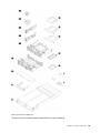
Enclosure components . . . . . . . . . . 22
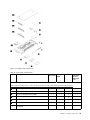
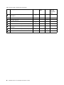
Compute node components . . . . . . . . 24
Power cords . . . . . . . . . . . . . . 27
Chapter 3. Network/Infrastructure
Planning . . . . . . . . . . . . . . . . 29
Chapter 4. Server setup checklist. . . 31
Solution package contents . . . . . . . . . . 31
Cable the solution . . . . . . . . . . . . . . 31
Power on the compute node . . . . . . . . . . 32
Power off the compute node . . . . . . . . 32
Set the network connection for the Lenovo XClarity
Controller . . . . . . . . . . . . . . . . . 32
Enable System Management Module network
connection via Lenovo XClarity Controller . . . 33
Configure ESXi . . . . . . . . . . . . . . . 33
Chapter 5. Installing and configuring
vCSA . . . . . . . . . . . . . . . . . . 35
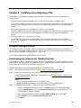
Using the ThinkAgile Installer . . . . . . . . . 35
Downloading and setting up the ThinkAgile
Installer . . . . . . . . . . . . . . . . 35
Running the ThinkAgile Installer . . . . . . . 36
Installing and configuring vCSA manually . . . . . 39
Adding the ThinkAgile VX7Y12 Series cluster to an
existing vCSA instance . . . . . . . . . . . . 39
Chapter 6. Installing and setting up
Lenovo XClarity Administrator. . . . . 41
Deploying Lenovo XClarity Administrator . . . . . 41
Managing ThinkAgile VX7Y12 Series Servers . . . 42
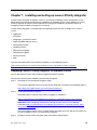
Chapter 7. Installing and setting up
Lenovo XClarity Integrator. . . . . . . 45
Deploying Lenovo XClarity Integrator for VMware
vCenter . . . . . . . . . . . . . . . . . . 45
Chapter 8. Hardware replacement
procedures . . . . . . . . . . . . . . . 47
Installation Guidelines . . . . . . . . . . . . 47
System reliability guidelines . . . . . . . . 48
Working inside the solution with the power
on . . . . . . . . . . . . . . . . . . 49
Handling static-sensitive devices . . . . . . 49
Drive replacement . . . . . . . . . . . . . . 49
Remove a hot-swap drive . . . . . . . . . 50
Install a hot-swap drive . . . . . . . . . . 51
Hot-swap power supply replacement . . . . . . 52
Remove a hot-swap power supply. . . . . . 53
Install a hot-swap power supply . . . . . . 55
Fan replacement . . . . . . . . . . . . . . 57
Remove a fan . . . . . . . . . . . . . . 58
Install a fan . . . . . . . . . . . . . . . 60
RAID or HBA adapter replacement . . . . . . . 62
Remove a RAID or HBA adapter . . . . . . 62
Install a RAID or HBA adapter . . . . . . . 64
EIOM replacement. . . . . . . . . . . . . . 65
Remove the EIOM . . . . . . . . . . . . 65
Install the EIOM . . . . . . . . . . . . . 67
PCIe adapter replacement. . . . . . . . . . . 68
Remove a PCIe adapter . . . . . . . . . . 68
Install a PCIe adapter . . . . . . . . . . . 70
DIMM replacement . . . . . . . . . . . . . 72
Remove a DIMM. . . . . . . . . . . . . 73
Memory module installation . . . . . . . . 74
M.2 backplane and M.2 drive replacement . . . . 79
Remove the M.2 drive . . . . . . . . . . 79
Install an M.2 drive . . . . . . . . . . . . 80
Chapter 9. Updating firmware. . . . . 83
Appendix A. Configuration
settings. . . . . . . . . . . . . . . . . 87
© Copyright Lenovo 2018 i


Chapter 1. Introduction
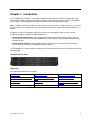
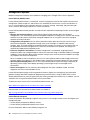
The ThinkAgile VX7Y12 Series is a 2U solution designed for high-volume network transaction processing.
This solution includes a single enclosure that can contain up to four compute nodes, which are designed to
deliver a dense, scalable platform for distributed enterprise and hyperconverged solutions.
Note: A VMware vSAN cluster requires a minimum of three or more servers. The best practice is to use three
or more servers of the same machine type and configuration to provide a balanced and high-performance
solution.
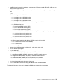
In addition, the server is designed to utilize the Lenovo system management tools to create a unified
hardware management solution for vSAN deployments:
• Lenovo XClarity Administrator, which provides firmware compliance functionality to ensure that the
VX7Y14 Series servers are running the appropriate level of firmware for Lenovo XClarity Controller, UEFI,
and PCIe devices.
• Lenovo XClarity Integrator, which provides VMware vCenter plug-in functionality so that ThinkAgile
VX7Y12 Series servers can be managed directly from vCenter.
The ThinkAgile VX7Y12 Series hardware is based on the ThinkSystem D2 Enclosure and ThinkSystem SD530
Compute Node.
ThinkAgile VX7Y12 Series
Helpful links
You might find the following links helpful:
Warranty lookup
Lenovo ServerProven
Lenovo open source projects
Lenovo product guides (Lenovo Press) Lenovo Configuration and Options
Guide
ThinkAgile VX Best Recipes
Lenovo Support
Lenovo forums Drivers and Firmware Updates Best
Practices
Lenovo security advisories
© Copyright Lenovo 2018 1

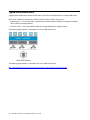
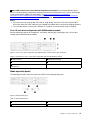
Typical vSAN architecture
A typical vSAN architecture includes three or more servers that are implemented as a single vSAN cluster.
Each server contributes storage to the vSAN cluster from the local disks on the server:
• Hybrid Cluster – The server provides a combination of solid state disks (SSDs) for caching and hard disk
drives (HDDs) for storage capacity.
• All-Flash Cluster – The server provides SSDs for caching and SSDs for storage capacity.
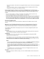
The following figure provides a conceptual view of the vSAN architecture:
The following figure provides a conceptual view of the vSAN architecture:
https://storagehub.vmware.com/t/vmware-vsan/vmware-r-vsan-tm-design-and-sizing-guide/
2 ThinkAgile VX Enclosure ThinkAgile VX3720 User’s Guide

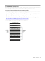
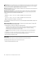
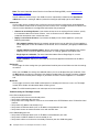
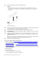
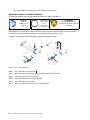
VX deployment architecture
When deploying a ThinkAgile VX7Y12 Series solution, the best practice is to use three or more servers of the
same machine type and configuration to provide a balanced and high-performance solution.
The systems are connected through switches for management and data:
• A dedicated management network is used by the Lenovo XClarity Administrator to communicate with the
Lenovo XClarity Controller (XCC) on each of the ThinkAgile VX7Y12 Series servers.
• A redundant 10Gbps Ethernet network is used for VMware vSphere management and vSAN data traffic.
The redundant Ethernet network is implement through two top-of-rack switches, such as the Lenovo
ThinkSystem NE1032 RackSwitch.
For more information about the Lenovo ThinkSystem NE1032 RackSwitch, see the following website:
https://lenovopress.com/lp0605-lenovo-thinksystem-ne1032-rackswitch
The following figure shows a typical ThinkAgile VX Series deployment:
Chapter 1. Introduction 3

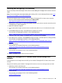
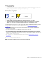
Identifying your server
When you contact Lenovo for help, the machine type and serial number information helps support
technicians to identify your server and provide faster service.
Note: The illustrations in this document might differ slightly from your model.
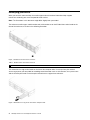
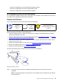
The enclosure machine type, model number and serial number are on the ID label that can be found on the
front of the enclosure, as shown in the following illustration.
Figure 1. ID label on the front of the enclosure
Table 1. ID label on the front of the enclosure
1 ID label
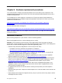
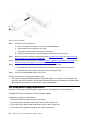
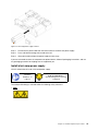
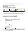
The network access tag can be found on the front of the compute node. You can pull way the network
access tag to paste your own label for recording some information such as the hostname, the system name
and the inventory bar code. Please keep the network access tag for future reference.
Figure 2. Network access tag on the front of the compute node
4 ThinkAgile VX Enclosure ThinkAgile VX3720 User’s Guide

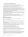
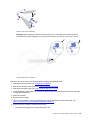
The node model number and serial number are on the ID label that can be found on the front of the compute
node (on the underside of the network access tag), as shown in the following illustration.
Figure 3. ID label on the front of the compute node
Specifications
The following information is a summary of the features and specifications of the solution. Depending on the
model, some features might not be available, or some specifications might not apply.
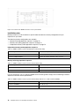
Enclosure specifications
Features and specifications of the enclosure.
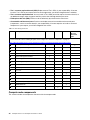
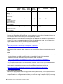
Table 2. Enclosure specifications
Specification Description
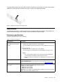
PCI expansion slots
(depending on the enclosure
model)
• PCIe 3.0 x8 shuttle:
– Supports up to eight low-profile PCIe 3.0 x8 adapters
One node supports up to two low-profile PCIe 3.0 x8 adapters from processor
1
• PCIe 3.0 x16 shuttle:
– Supports up to four low-profile PCIe 3.0 x16 adapters
One node supports one low-profile PCIe 3.0 x16 adapters from processor 1
Notes:
1. PCIe 3.0 x16 shuttle supports PCIe cassettes that can be installed and
removed without removing the shuttle from the enclosure.
2. Ensure to power off the node before unseating the PCIe cassette from the
shuttle.
Hot-swap fans • Three 60x60x56mm fans
• Two 80x80x80mm fans
Note: Access these fans from the top of the enclosure (see
Remove the fan cover).
Power supply (depending on
the model)
Supports up to two hot-swap power supplies for redundancy support. (Except for the
application of 240V DC applied through C14 input connect)
• 1100-watt ac power supply
• 1600-watt ac power supply
• 2000-watt ac power supply
Important: Power supplies and redundant power supplies in the enclosure must be
with the same power rating, wattage or level.
Chapter 1. Introduction 5

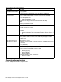
Table 2. Enclosure specifications (continued)
Specification
Description
System Management Module
(SMM)
• Hot-swappable
• Equipped with ASPEED controller
• Offers RJ45 port for management of nodes and SMM over 1G Ethernet
Ethernet I/O ports Access to a pair of on-board 10Gb connections through two types of optional
enclosure level EIOM cards.
• Two optional EIOM cards:
– 10Gb 8-port EIOM SFP+
– 10Gb 8-port EIOM Base-T (RJ45)
• Minimum networking speed requirement for the EIOM card: 1Gbps
Note:
The EIOM card is installed in the enclosure and it provides direct access to LAN
functions provided by each node.
Size 2U enclosure
• Height: 87.0 mm (3.5 inches)
• Depth: 891.5 mm (35.1 inches)
• Width: 488.0 mm (19.3 inches)
• Weight:
– Minimum configuration (with one minimal configuration node): 22.4 kg (49.4 lbs)
– Maximum configuration (with four maximal configuration nodes): 55.0 kg (121.2
lbs)
Acoustical noise emissions With the maximum configuration of four nodes with two processors installed, full
memory installed, full drives installed, and two 2000-watt power supplies installed:
• Operation: 6.8 bels
• Idle: 6.2 bels
Heat output (based on two
2000-watt power supplies)
Approximate heat output:
• Minimum configuration (with one minimal configuration node): 604.1 BTU per hour
(177 watts)
• Maximum configuration (with four maximal configuration nodes): 7564.4 BTU per
hour (2610 watts)
Electrical input
• Sine-wave input (50-60 Hz) required
• Input voltage low range: 1100W is limited to 1050W
– Minimum: 100 V AC
– Maximum: 127 V AC
• Input voltage high range: 1100W/1600W/2000W
– Minimum: 200 V AC
– Maximum: 240 V AC
• Input kilovolt-amperes (kVA), approximately:
– Minimum: 0.153 kVA
– Maximum: 2.61 kVA
Compute node specifications
Features and specifications of the compute node.
6
ThinkAgile VX Enclosure ThinkAgile VX3720 User’s Guide

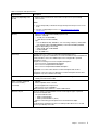
Table 3. Compute node specifications
Specification
Description
Processor (depending on the
model)
• Supports up to two Intel Xeon series multi-core processors (one installed)
• Level-3 cache
Notes:
1. Use the Setup utility to determine the type and speed of the processors in the
node.
2. For a list of supported processors, see
http://www.lenovo.com/us/en/
serverproven/
.
Memory
• Minimum: 8 GB (single DDR4 DIMM per processor)
• Maximum: 1,024 GB
– 512 GB (16 x 32 GB RDIMM)
– 1,024 GB (16 x 64 GB LRDIMM)
• Type:
– PC4-21300 (dual-rank), 2666 MT/s, error correcting code (ECC), double-data-
rate 4 (DDR4) registered DIMM (RDIMM) or load reduced DIMM (LRDIMM)
• Supports (depending on the model):
– 8 GB, 16 GB, and 32 GB RDIMM
– 64 GB LRDIMM
• Slots: 16 DIMM slots
Drive bays
Supports up to six 2.5-inch hot-swap SAS/SATA/NVMe drive bays.
Attention: As a general consideration, do not mix standard 512-byte and advanced
4-KB format drives in the same RAID array because it might lead to potential
performance issues.
Supports the following 2.5-inch hot-swap drive backplanes:
• Four 2.5-inch hot-swap SAS/SATA backplane
• Six 2.5-inch hot-swap SAS/SATA backplane
• Six 2.5-inch hot-swap SAS/SATA/NVMe backplane
Important: Do not mix nodes with the four-drive backplane and six-drive
backplanes in the same enclosure. Mixing the four-drive backplane and six-drive
backplanes may cause unbalanced cooling.
Host bus adapters
The following host bus adapter (HBA) is supported on ThinkAgile VX3720:
• ThinkSystem 430-8i Dense HBA
Video controller (integrated
into Lenovo XClarity
Controller)
• ASPEED
• SVGA compatible video controller
• Avocent Digital Video Compression
• Video memory is not expandable
Note: Maximum video resolution is 1920 x 1200 at 60 Hz.
Ethernet I/O port Access to a pair of on-board 10Gb connections through two types of optional
enclosure level EIOM cards.
• Two optional EIOM cards:
– 10Gb 8-port EIOM SFP+
– 10Gb 8-port EIOM Base-T (RJ45)
• Minimum networking speed requirement for the EIOM card: 1Gbps
Note:
The EIOM card is installed in the enclosure and it provides direct access to LAN
functions provided by each node.
Chapter 1. Introduction 7

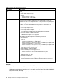
Table 3. Compute node specifications (continued)
Specification
Description
Size
Node
• Height: 41.0 mm (1.7 inches)
• Depth: 562.0 mm (22.2 inches)
• Width: 222.0 mm (8.8 inches)
• Weight:
– Minimum weight: 3.5 kg (7.7 lb)
– Maximum weight: 7.5 kg (16.6 lb)
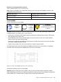
Environment
The ThinkAgile VX3720 complies with ASHRAE class A2 specifications.
Depending on the hardware configuration, some solution models comply with
ASHRAE Class A3 or Class A4 specifications. System performance may be impacted
when operating temperature is outside ASHRAE A2 specification or fan failed
condition. To comply with ASHRAE Class A3 and Class A4 specifications, the
ThinkAgile VX3720 needs to meet the following hardware configuration requirements:
• Lenovo supported processors.
For unsupported processors, see the following attention for details
1
.
• Lenovo supported PCIe adapters.
For unsupported PCIe adapters, see the following attention for details
2
.
• Two power supplies installed for redundancy.
1100-watt power supplies are not supported.
The ThinkAgile VX3720 is supported in the following environment:
• Air temperature:
Power on
3
:
– ASHRAE Class A2: 10°C - 35°C (50°F - 95°F); Above 900 m (2,953 ft), de-rated
maximum air temperature 1°C / 300m (984 ft)
– ASHRAE Class A3: 5°C - 40°C (41°F - 104°F); Above 900 m (2,953 ft), de-rated
maximum air temperature 1°C / 175m (574 ft)
– ASHRAE Class A4: 5°C - 45°C (41°F - 113°F); Above 900 m (2,953 ft), de-rated
maximum air temperature 1°C / 125m (410 ft)
Power off
4
: 5°C to 45°C (41°F to 113°F)
• Maximum altitude: 3,050 m (10,000 ft)
• Relative Humidity (non-condensing):Power on
3
:
– ASHRAE Class A2: 8% - 80%, maximum dew point : 21°C (70°F)
– ASHRAE Class A3: 8% - 85%, maximum dew point : 24°C (75°F)
– ASHRAE Class A4: 8% - 90%, maximum dew point : 24°C (75°F)
Shipment/storage: 8% - 90%
• Particulate contamination:
Airborne particulates and reactive gases acting alone or in combination with other
environmental factors such as humidity or temperature might pose a risk to the
solution.
Power rating
12 V DC, 60 A
Attention:
1. The following processors are not supported with ASHRAE Class A3 and Class A4 specifications:
• 165W processor, 28-core, 26-core or 18-core (Intel Xeon 8176, 8176M, 8170, 8170M, and 6150)
• 150W processor, 26-core, 24-core, 20-core, 16-core or 12-core (Intel Xeon 8164, 8160, 8160M, 8158,
6148, 6142, 6142M, and 6136)
• 140W processor, 22-core or 18-core (Intel Xeon 6152, 6140, and 6140M)
• 140W processor, 14-core (Intel Xeon 6132)
8
ThinkAgile VX Enclosure ThinkAgile VX3720 User’s Guide

• 130W processor, 8-core (Intel Xeon 6134 and 6134M)
• 125W processor, 20-core, 16-core or 12-core (Intel Xeon 6138, 6138T, 6130T, 6126)
• 115W processor, 6-core (Intel Xeon 6128)
• 105W processor, 14-core or 4-core (Intel Xeon 8156, 5122, and 5120T)
• 70W processor, 8-core (Intel Xeon 4109T)
Note: The listed processors are included but not limited to the above list only.
2. The following processors are not supported with ASHRAE Class A2, Class A3 and Class A4
specifications. The following processors are provided for special bid configuration only and need
customer’s acceptance on the limitation consequence. The limitation includes experiencing power
capping and a slight drop in performance when ambient is above 27°C.
• 205W processor, 28-core or 24-core (Intel Xeon 8180, 8180M and 8168)
• 200W processor, 18-core (Intel Xeon 6154)
• 165W processor, 12-core (Intel Xeon 6146)
• 150W processor, 24-core (Intel Xeon 8160T)
• 150W processor, 8-core (Intel Xeon 6144)
• 125W processor, 12-core (Intel Xeon 6126T)
Note: The listed processors are included but not limited to the above list only.
3. The following PCIe adapters are not supported with ASHRAE Class A3 and Class A4 specifications:
• Mellanox NIC with active optical cable
• PCIe SSD
• GPGPU card
Note: The listed PCIe adapters are included but not limited to the above list only.
4. Enclosure is powered on.
5. Enclosure is removed from original shipping container and is installed but not in use, for example, during
repair, maintenance, or upgrade.
Chapter 1. Introduction 9

Management options
Multiple management interfaces are available for managing your ThinkAgile VX7Y12 Series appliance.
Lenovo XClarity Administrator
Lenovo XClarity Administrator is a centralized, resource-management solution that simplifies infrastructure
management, speeds responses, and enhances the availability of Lenovo server systems and solutions. It
runs as a virtual appliance that automates discovery, inventory, tracking, monitoring, and provisioning for
server, network, and storage hardware in a secure environment.
Lenovo XClarity Administrator provides a central interface to perform the following functions for all managed
endpoints:
• Manage and monitor hardware. Lenovo XClarity Administrator provides agent-free hardware
management. It can automatically discover manageable endpoints, including server, network, and storage
hardware. Inventory data is collected for managed endpoints for an at-a-glance view of the managed
hardware inventory and status.
• Configuration management. You can quickly provision and pre-provision all of your servers using a
consistent configuration. Configuration settings (such as local storage, I/O adapters, boot settings,
firmware, ports, and Lenovo XClarity Controller and UEFI settings) are saved as a server pattern that can
be applied to one or more managed servers. When the server patterns are updated, the changes are
automatically deployed to the applied servers.
• Firmware compliance and updates. Firmware management is simplified by assigning firmware-
compliance policies to managed endpoints. When you create and assign a compliance policy to managed
endpoints, Lenovo XClarity Administrator monitors changes to the inventory for those endpoints and flags
any endpoints that are out of compliance.
When an endpoint is out of compliance, you can use Lenovo XClarity Administrator to apply and activate
firmware updates for all devices in that endpoint from a repository of firmware updates that you manage.
• Operating System deployment. You can use Lenovo XClarity Administrator to manage a repository of
operating-system images and to deploy operating-system images to up to 28 managed servers
concurrently.
• Service and support. You can manually collect diagnostic files, open a problem record, and send
diagnostic files to the Lenovo Support Center.
Lenovo XClarity Administrator can be integrated into external, higher-level management and automation
platforms through open REST application programming interfaces (APIs). Using the REST APIs, Lenovo
XClarity Administrator can easily integrate with your existing management infrastructure. In addition, you can
automate tasks using the PowerShell toolkit or the Python toolkit.
To obtain the latest version of the Lenovo XClarity Administrator, see:
https://datacentersupport.lenovo.com/documents/LNVO-LXCAUPD
Documentation for Lenovo XClarity Administrator is available at:
http://sysmgt.lenovofiles.com/help/topic/com.lenovo.lxca.doc/aug_product_page.html
Lenovo XClarity Integrator
Lenovo also provides the following integrators that you can use to manage Lenovo servers from higher-level
management tools:
• Lenovo XClarity Integrator for VMware vCenter
• Lenovo XClarity Integrator Microsoft System Center
For more information about Lenovo XClarity Integrator, see:
10
ThinkAgile VX Enclosure ThinkAgile VX3720 User’s Guide


12 ThinkAgile VX Enclosure ThinkAgile VX3720 User’s Guide

Chapter 2. Solution components
Use the information in this section to learn about each of the components associated with your solution.
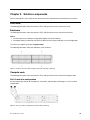
Front view
The following illustration shows the controls, LEDs, and connectors on the front of the server.
Enclosure
The following illustration shows the controls, LEDs, and connectors on the front of the enclosure.
Notes:
1. The illustrations in this document might differ slightly from your hardware.
2. For proper cooling, a node filler has to be installed into every empty node bay in every configuration.
The enclosure supports up to four compute nodes.
The following illustration shows the node bays in the enclosure.
Figure 4. Enclosure front view with compute nodes and node bay numbering
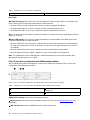
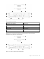
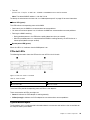
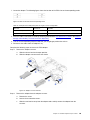
Compute node
The following illustration shows the controls, LEDs, and connectors on the front of the compute node.
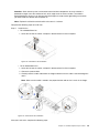
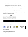
Six 2.5-inch drive configuration
See the following illustration for components, connectors and drive bay numbering in six 2.5-inch drive
configuration.
Figure 5. Six 2.5-inch drive configuration and drive bay numbering
© Copyright Lenovo 2018 13

Table 4. Components in six 2.5-inch drive configuration
1 Activity LED (green) 2 Status LED (yellow)
Drive LEDs:
1 Activity LED (green): Green LEDs are on all hot swap drives. When this green LED is lit, it indicates that
there is activity on the associated hard disk drive or solid-state drive.
• When this LED is flashing, it indicates that the drive is actively reading or writing data.
• For SAS and SATA drives, this LED is off when the drive is powered but not active.
• For NVMe (PCIe) SSDs, this LED is on solid when the drive is powered but not active.
Note: The drive activity LED might be in a different location on the front of the drive, depending on the drive
type that is installed.
2 Status LED (yellow): The state of this yellow LED indicates an error condition or the RAID status of the
associated hard disk drive or solid-state drive:
• When the yellow LED is lit continuously, it indicates that an error has occurred with the associated drive.
The LED turns off only after the error is corrected. You can check event logs to determine the source of
the condition.
• When the yellow LED flashes slowly, it indicates that the associated drive is being rebuilt.
• When the yellow LED flashes rapidly, it indicates that the associated drive is being located.
Note: The hard disk drive status LED might be in a different location on the front of the hard disk drive,
depending on the drive type that is installed.
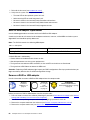
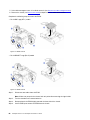
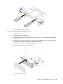
Five 2.5-inch drive configuration with KVM breakout module
See the following illustration for components, connectors and drive bay numbering in five 2.5-inch drive
configuration with KVM breakout module.
Figure 6. Five 2.5-inch drive configuration with KVM breakout module and drive bay numbering
Table 5. Components in five 2.5-inch drive configuration with the KVM breakout module
1 KVM connector
3 Micro USB connector for Lenovo XClarity Controller
management
2 USB 3.0 connector
4 KVM breakout module
KVM breakout module comes with the following connectors:
1 KVM connector: Connect the console breakout cable to this connector (see KVM breakout cable more
information).
2 USB 3.0 connector: Connect a USB device to this USB 3.0 connector.
14
ThinkAgile VX Enclosure ThinkAgile VX3720 User’s Guide

3 Micro USB connector for Lenovo XClarity Controller management: The connector provides direct
access to Lenovo XClarity Controller by allowing you to connect a mobile device to the system and manage
it with Lenovo XClarity Mobile. For more details, see
http://sysmgt.lenovofiles.com/help/topic/
com.lenovo.systems.management.xcc.doc/product_page.html
and http://sysmgt.lenovofiles.com/help/topic/
com.lenovo.lxca.doc/aug_product_page.html
for more information.
Notes:
1. Ensure that you use a high-quality OTG cable or a high-quality converter when connecting a mobile
device. Be aware that some cables that are supplied with mobile devices are only for charging purposes.
2. Once a mobile device is connected, it indicates it is ready to use and no further action is required.
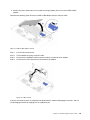
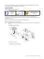
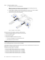
Four 2.5-inch drive configuration with KVM breakout module
See the following illustration for components, connectors and drive bay numbering in four 2.5-inch drive
configuration with KVM breakout module.
Figure 7. Four 2.5-inch drive configuration with KVM breakout module and drive bay numbering
Table 6. Components in four 2.5-inch drive configuration with the KVM breakout module
1 KVM connector 4 KVM breakout module
2 USB 3.0 connector
5 Drive bay filler
3 Micro USB connector for Lenovo XClarity Controller
management
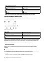
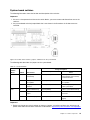
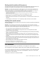
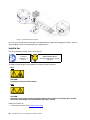
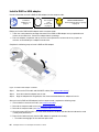
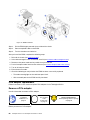
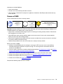
Node operator panel
The following illustration shows the controls and LEDs on the node operator panel.
Figure 8. Node operator panel
Table 7. Node operator panel
1 NMI pinhole
3 Identification button/LED
2 System error LED 4 Power button/LED
Chapter 2. Solution components 15

1 NMI pinhole: Press this pinhole to force a non-maskable interrupt to the processor. It allows you to blue
screen the solution and take a memory dump (use this button only when directed by the service support).
You have to use the end of a straightened paper clip to press the pinhole.
2 System error LED: When this LED is lit (yellow), it indicates that a system error has occurred. Check the
event log for additional information.
3 Identification button/LED: The system administrator can light this LED to aid in visually locating the
compute node. This LED can turned on locally by pressing button or using the following commands to
control the identification LED and locate the compute node.
• Turn on:
ipmitool.exe -I lanplus -H <XCC’s IP> -U USERID -P PASSW0RD raw 0x3a 0x08 0x01 0x00
• Turn off:
ipmitool.exe -I lanplus -H <XCC’s IP> -U USERID -P PASSW0RD raw 0x3a 0x08 0x01 0x01
Note: The default XCC’s IP address is 192.168.70.125
To easily identify the solution from the rear side, see “System Management Module (SMM)” on page 18 for
more information.
4 Power button/LED: When this LED is lit (green), it indicates that the node has power. This green LED
indicates the power status of the compute node:
• Flashing rapidly: The LED flashes rapidly for the following reasons:
– The node has been installed in an enclosure. When you install the compute node, the LED flashes
rapidly for up to 90 seconds while the Lenovo XClarity Controller in the node is initializing.
– The power source is not sufficient to turn on the node.
– The Lenovo XClarity Controller in the node is not communicating with the System Management
Module.
• Flashing slowly: The node is connected to the power through the enclosure and ready to turn on.
• Lit continuously: The node is connected to the power through the enclosure.
• Not lit continuously: No power on node.
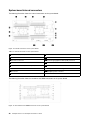
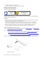
Rear view
The following illustration shows the connectors and LEDs on the rear of the enclosure.
The following illustration shows the rear view of the entire system.
• Shuttle with eight low profile PCIe x8 slots
16
ThinkAgile VX Enclosure ThinkAgile VX3720 User’s Guide
Page is loading ...
Page is loading ...
Page is loading ...
Page is loading ...
Page is loading ...
Page is loading ...
Page is loading ...
Page is loading ...
Page is loading ...
Page is loading ...
Page is loading ...
Page is loading ...
Page is loading ...
Page is loading ...
Page is loading ...
Page is loading ...
Page is loading ...
Page is loading ...
Page is loading ...
Page is loading ...
Page is loading ...
Page is loading ...
Page is loading ...
Page is loading ...
Page is loading ...
Page is loading ...
Page is loading ...
Page is loading ...
Page is loading ...
Page is loading ...
Page is loading ...
Page is loading ...
Page is loading ...
Page is loading ...
Page is loading ...
Page is loading ...
Page is loading ...
Page is loading ...
Page is loading ...
Page is loading ...
Page is loading ...
Page is loading ...
Page is loading ...
Page is loading ...
Page is loading ...
Page is loading ...
Page is loading ...
Page is loading ...
Page is loading ...
Page is loading ...
Page is loading ...
Page is loading ...
Page is loading ...
Page is loading ...
Page is loading ...
Page is loading ...
Page is loading ...
Page is loading ...
Page is loading ...
Page is loading ...
Page is loading ...
Page is loading ...
Page is loading ...
Page is loading ...
Page is loading ...
Page is loading ...
Page is loading ...
Page is loading ...
Page is loading ...
Page is loading ...
Page is loading ...
Page is loading ...
Page is loading ...
Page is loading ...
Page is loading ...
Page is loading ...
Page is loading ...
Page is loading ...
Page is loading ...
Page is loading ...
Page is loading ...
Page is loading ...
-
 1
1
-
 2
2
-
 3
3
-
 4
4
-
 5
5
-
 6
6
-
 7
7
-
 8
8
-
 9
9
-
 10
10
-
 11
11
-
 12
12
-
 13
13
-
 14
14
-
 15
15
-
 16
16
-
 17
17
-
 18
18
-
 19
19
-
 20
20
-
 21
21
-
 22
22
-
 23
23
-
 24
24
-
 25
25
-
 26
26
-
 27
27
-
 28
28
-
 29
29
-
 30
30
-
 31
31
-
 32
32
-
 33
33
-
 34
34
-
 35
35
-
 36
36
-
 37
37
-
 38
38
-
 39
39
-
 40
40
-
 41
41
-
 42
42
-
 43
43
-
 44
44
-
 45
45
-
 46
46
-
 47
47
-
 48
48
-
 49
49
-
 50
50
-
 51
51
-
 52
52
-
 53
53
-
 54
54
-
 55
55
-
 56
56
-
 57
57
-
 58
58
-
 59
59
-
 60
60
-
 61
61
-
 62
62
-
 63
63
-
 64
64
-
 65
65
-
 66
66
-
 67
67
-
 68
68
-
 69
69
-
 70
70
-
 71
71
-
 72
72
-
 73
73
-
 74
74
-
 75
75
-
 76
76
-
 77
77
-
 78
78
-
 79
79
-
 80
80
-
 81
81
-
 82
82
-
 83
83
-
 84
84
-
 85
85
-
 86
86
-
 87
87
-
 88
88
-
 89
89
-
 90
90
-
 91
91
-
 92
92
-
 93
93
-
 94
94
-
 95
95
-
 96
96
-
 97
97
-
 98
98
-
 99
99
-
 100
100
-
 101
101
-
 102
102


Lenovo ThinkAgile VX3720 7Y12 User manual
- Type
- User manual
Ask a question and I''ll find the answer in the document
Finding information in a document is now easier with AI
Related papers
-
Lenovo ThinkAgile CP 4000 Series Installation guide
-
-
-
-
Lenovo ThinkSystem SR645 Setup Manual
-
Lenovo ThinkAgile VX7820 Appliance User guide
-
Lenovo ThinkAgile VX2320 User manual
-
Lenovo ThinkAgile VX5520 User manual
-
-
Other documents
-
 Yottamaster DF4RU3 User guide
-
Juniper JCS 1200 Removing Manual
-
-
Dell VMware VSAN Quick start guide
-
H3C UniServer T1100 G3 User manual
-
-
-
Dell EMC PowerStore 5000X Owner's manual
-
-
Ciprico 21021625 B User manual
