Page is loading ...

Table of Content ...............................................................................................................................................................................i
Parts List
Parts List..................................................................................................................................ii
Assembly Note
Assembly Note .........................................................................................................................v
Warranty Information ................................................................................................................v
Preparation
Step 1: Removal Steps ............................................................................................................. 1
Assembly
Step 2: Motor Plate Installation ................................................................................................. 3
Step 3: Take Up Rail Mount Installation ...................................................................................... 6
Step 4: Slot Plate Installation .................................................................................................... 7
Step 5: Check Connections ....................................................................................................... 8
Step 6: Cover Installation ......................................................................................................... 9
Step 7: Ethernet Cable Installation ...........................................................................................11
Step 8: Open Market Bracket Installation ..................................................................................13
Step 9: Magnet Bracket Installation ..........................................................................................15
Step 10: Idler Rail Assembly ....................................................................................................16
Step 11: Rail Installation ..........................................................................................................18
Setup
Step 12: Adjustments ..............................................................................................................20
Step 13: Fabric Installation ......................................................................................................22
Step 14: Calibration .................................................................................................................25
Step 15: Function .................................................................................................................... 26
Trouble Shooting Guide ......................................................................................................27
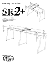
Copyright July 24, 2019
Jim M. Bagley, GraceWood, Inc
(Reproduction Prohibited)
Version 1.9

Left Cover
(1)
Right Cover
(1)
Left Motor Plate
Assembly
(1)
Right Motor
Plate Assembly
(1)
|Parts List Gliding Rail Accessory
Idler Rail
Fixed End
(1)
Idler Rail
Floating End
(1)
Idler Rail
Middle Section
(2)
Idler Rail
Coupler
(3)
Idler Rail 1ft
Section
(1)
Parts List Box 1
ii

Slot Plate Cap
(4)
Fabric
Clip
(6)
Rail Slot
Cover Center
(2)
Rail Slot
Cover Sides
(4)
Zip Tie Mount
(12)
Zip Tie
(14)
Ethernet
Cable
(1)
Open Market
Sensor Bracket
(1)
|Parts List Gliding Rail Accessory
Rail Holder
Cap
(2)
Rail Tensioner
Cap
(1)
Magnet
Mount
(1)
Power Supply
(2)
Right Take Up
Rail Mount Assembly
(1)
Left Take Up
Rail Mount Assembly
(1)
Hardware Box
iii

5mm Allen
Wrench
(1)
2.5mm Allen
Wrench
(1)
4mm Allen
Wrench
(1)
M8 x 16mm
SBHCS
(16)
M5 x 20mm
SBHCS
(6)
6mm Allen
Wrench
(1)
M6 x 10mm
SBHCS
(8)
|Parts List Gliding Rail Accessory
M6 x 20mm
SBHCS
(1)
M8 x 10mm
SBHCS
(4)
3mm Allen
Wrench
(1)
Hardware Box
iv

If you have purchased a Grace Continuum Frame and
Gliding Rail Accessory together, Complete the Continuum
Frame Assembly Instructions prior to proceeding with
the assembly of the Gliding Rail Accessory. If you have
purchased the Batting Rail Accessory, it is recommended
you assembly the Batting Rail Accessory prior to the
Gliding Rail Accessory.
Preparation and Warranty
Warranty Information for your Continuum Gliding Rail
Accessory
The Continuum Gliding Rail Accessory has a One-Year limited warranty on all parts. The
Grace Company will repair or replace, at its discretion, any part with problems due to
our manufacturing or defects in materials. This warranty does not cover parts damaged
through misuse, improper storage, improper assembly, loss, natural events, and willful
destruction. Parts must be returned to the Grace Company, shipping prepaid, before we
can repair or replace them. We will promptly return the repaired/replaced part at our
expense if done within a year of the purchase date.
X
?
1-800-264-0644
v

Step 1 - Removal Steps
Tools Needed:
4mm Allen Wrench
6mm Allen Wrench
1-2 Remove your Sewing Machine from the Bottom
Carriage.
Note: Be sure to unplug all cords rst.
1-3 Remove the Slot Plate Covers from the right and
left side by removing the (2) M6 x 16mm SBHCS
from each side using the 4mm Allen Wrench.
Note: Set M6 x 16mm SBHCS to the side for use
in Step 4.
1-1 Remove the Hand Wheel Rail Assembly.
Hand Wheel Rail
Assembly
Slot Plate
Cover
M6 x 16mm
SBHCS
Preparation
1

1-4 Remove the Ratchet Stop Assembly from the
Ratchet Back Rail Support using the 4mm Allen
Wrench.
Remove Ratchet
Assembly
Remove
Re-install without
Ratchet Wheel
Ratchet Wheel
Preparation
6mm Allen
Wrench
6mm Allen
Wrench
1-5 Remove the Hand Wheel Assembly using the 6mm Allen Wrench, then re-install without the Ratchet
Wheel.
2

Left Motor Plate
Assembly (1)
Right Motor Plate
Assembly (1)
M8 x 16mm
SBHCS (8)
Step 2 - Motor Plate Installation
Parts Needed:
Tools Needed:
5mm Allen Wrench
Assembly
2-1 Secure the Left Motor Plate Assembly to the Left Leg using (2) M8 x 16mm SBHCS.
Note: Do not tighten screws at this time.
Left Motor Plate
Assembly
M8 x 16mm
SBHCS
Left Leg
Assembly
3

Right Motor Plate
Assembly
2-3 Secure the Right Motor Plate Assembly to the Right Leg using (2) M8 x 16mm SBHCS.
Note: Do not tighten screws at this time.
Right Leg
Assembly
M8 x 16mm
SBHCS
2-2 Secure the Left Motor Plate Assembly to the Left Leg using (2) M8 x 16mm SBHCS.
Note: Tighten all screws at this time.
M8 x 16mm
SBHCS
Left Leg
Assembly
Assembly
4

Assembly
2-4 Secure the Right Motor Plate Assembly to the Right Leg using (2) M8 x 16mm SBHCS.
Note: Tighten all screws at this time.
Right Leg
Assembly
M8 x 16mm
SBHCS
5

Assembly
Right Take Up
Rail Mount
Assembly (1)
M6 x 10mm
SBHCS (6)
Step 3 - Take Up Rail Mount Installation
Parts Needed:
Tools Needed:
4mm Allen Wrench
3-2 It may be required to move the Cam Slot
towards the back of the frame to allow the Take
Up Rail Mounts to insert as shown in Step 3-3.
Cam Slot
Left Take Up
Rail Mount
Assembly (1)
3-1 Identify the dierence between the Right Take
Up Rail Mount Assembly and the Left Take Up Rail
Mount Assembly.
Left Right
Note
Open Hole
Location
Note
Open Hole
Location
3-3 Install the Left Take Up Rail Mount Assembly
into the Cam Slot on the left Motor Plate Assembly.
Note: Repeat for the opposite side.
Left Take Up
Rail Mount
Assembly
Cam Slot
6

4-1 Install the Rail Slot Covers and Slot Plate Caps
using (2) M6 x 16mm SBHCS from Step 1-3.
Note: Do not tighten screws until step 12-7.
Repeat for opposite side.
Rail Slot Cover
Center (2)
Rail Slot Cover
Side (4)
Slot Plate Cap (4)
Step 4 - Slot Cover Installation
Parts Needed:
M6 x 16mm
SBHCS (4)
(From Step 1-3)
Tools Needed:
4mm Allen Wrench
M6 x 10mm
SBHCS
3-4 Secure the Take Up Rail Mount Assemblies into
the Cam Slots using (3) M6 x 10mm SBHCS.
Note: Repeat for opposite side.
Left Frame End
Right Frame End
Note: Unused
hole location
Note: Unused
hole location
3-5 Unused holes in the Take Up Rail Mounts should
be to the outside of the frame.
Assembly
Rail Slot
Cover Side
Slot Plate
Cap
M6 x 16mm
SBHCS
Rail Slot
Cover Side
Rail Slot
Cover Center
7

Assembly
Step 5 - Check Connections
5-1 Plug in the Motor Cable to the correct port on
the Motor Control Board for each side.
Motor Control
Board
Motor
Cable
8

Assembly
Left Cover
Left Cover (1) Right Cover (1)
M8 x 16mm
SBHCS (8)
Step 6 - Cover Installation
Parts Needed:
Tools Needed:
5mm Allen Wrench
6-1 Install the Left Cover using (4) M8 x 16mm
SBHCS.
Note: Do not tighten screws at this time.
M8 x 10mm
SBHCS (4)
M8 x 16mm
SBHCS
6-2 Install the (2) M8 x 10mm SBHCS and tighten
all (6) screws.
M8 x 10mm
SBHCS
9

Assembly
Right Cover
Motor Control
Board
Rotary
Switch
6-3 Plug the Rotary Switch into the Motor Control
Board.
Note: Be sure to not pinch the Rotary Switch Cable
when installing the Right Cover.
Rotary
Switch
Cable
M8 x 16mm
SBHCS
Right Cover
6-4 Install the Right Cover using (4) M8 x 16mm
SBHCS.
Note: Be sure to not pinch the Rotary Switch Cable
when installing the Right Cover. Do not tighten
screws at this time.
M8 x 10mm
SBHCS
6-5 Install the (2) M8 x 10mm SBHCS and tighten
all (6) screws.
10

Assembly
Ethernet
Cable
Ethernet
Cable
7-2 Connect the Ethernet Cable to the Right Motor
Control Board.
7-1 Connect the Ethernet Cable to the Left Motor
Control Board.
Ethernet Cable (1) Zip Tie (7) Zip Tie Mount (7)
Step 7 - Ethernet Cable Installation
Parts Needed:
Left Motor
Control Board
Right Motor
Control Board
11

Assembly
Zip Tie
Mount
Zip Tie
Zip Tie
Mount
Zip Tie
Mount
Ethernet
Cable
7-3 Secure (7) Zip Tie Mounts to the bottom of the frame by removing the paper from the double faced
tape and sticking them to the cross bars on the underside of the tables.
7-4 Insert the (7) Zip Ties into the Zip Tie Mounts and use them the secure the Ethernet Cable to the
bottom of the table.
Note: Do not over tighten the zip ties. For excess Cable, loop and use additional Zip Ties and Zip Tie
Mounts to secure to the underside of the Frame.
Cross
Bars
12

Assembly
8-2 Adjust each Sensor to the proper setting for
your machine with the Sensor centered on the
correct indication line and tighten screws.
21” Machine
15” Machine
8-1 Loosen the M4 x 25mm SBHCS that secure the
Sensors.
Sensor
M4 x 25mm
SBHCS
Sensor
19” Machine
Open Market
Sensor Bracket (1)
M6 x 10mm
SBHCS (2)
Zip Tie (1) Zip Tie Mount (1)
Step 8 - Open Market Bracket Installation
Parts Needed:
Tools Needed:
2.5mm Allen Wrench
13

Assembly
Zip Tie
Mount
Zip Tie
Open Market
Sensor
Bracket
M6 x 10mm
SBHCS
8-3 Install the Open Market Sensor Bracket onto
the Bottom Carriage using (2) M6 x 10mm SBHCS.
Note: Do not tighten screws at this time.
8-4 Verify the Sensor Cables are attached to the
Open Market Sensor Bracket using (1) Zip Tie
Mount and (1) Zip Tie.
Back of
Carriage
Channel
Lock
Front of
Carriage
Front
Rear
1
1
2
2
Note: Check that the sensors are plugged into the proper port.
14

Assembly
Magnet
Bracket
M6 x 20mm
SBHCS
9-3 Adjust the Open Market Sensor Bracket so
there is less than 1/4” between the Sensor and the
Magnet. Tighten the (2) M6 x 10mm SBHCS on
the Open Market Sensor Bracket.
M6 x 10mm
SBHCS
Magnet
Open Market
Sensor Bracket
Sensor
Magnet Bracket (1)
M6 x 20mm
SBHCS (1)
Step 9 - Magnet Bracket Installation
Parts Needed:
9-1 Install the Magnet Bracket onto the right front
wheel of the sewing machine using (1) M6 x 20mm
SBHCS.
Note: The Magnet Bracket should point to the
front of the Sewing Machine.
9-2 Place your Sewing Machine on the bottom
carriage with the Magnet Bracket located between
the (2) Sensors.
Tools Needed:
4mm Allen Wrench
Magnet
Bracket
Sensor
Sensor
15
/