Page is loading ...

Instruction Manual
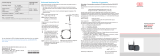
eddyNCDT 3300/3301
ES04
EU05
ES08
EU1
ES1
ES2
EU3
ES4
EU6
EU8
EU15
EU22
EU40
EU80

MICRO-EPSILON MESSTECHNIK
GmbH & Co. KG
Koenigbacher Strasse 15
94496 Ortenburg / Germany
Tel. +49 (0) 8542 / 168-0
Fax +49 (0) 8542 / 168-90
e-mail: [email protected]
www.micro-epsilon.com
Certified acc. to DIN EN ISO 9001: 2008
Software Version: V1.2
Non-contact displacement measurement system

eddyNCDT 3300/3301
Contents
1. Safety ........................................................................................................................................ 5
1.1 Symbols Used ................................................................................................................................ 5
1.2 Warnings ......................................................................................................................................... 5
1.3 Notes on CE Identification .............................................................................................................. 5
1.4 Proper Use ...................................................................................................................................... 6
1.5 Proper Environment ....................................................................................................................... 6
2. System Description .................................................................................................................. 7
2.1 Measurement Principle ................................................................................................................... 7
2.2 Structure of the Measurement System .......................................................................................... 7
2.2.1 Front View Controller ...................................................................................................................... 8
2.2.2 Rear View Controller ..................................................................................................................... 10
2.3 Glossary ........................................................................................................................................ 10
2.4 Technical Data .............................................................................................................................. 11
3. Delivery ................................................................................................................................... 12
3.1 Supplied Items, Unpacking .......................................................................................................... 12
3.2 Storage ......................................................................................................................................... 12
4. Installation and Assembly ...................................................................................................... 13
4.1 Precautions ................................................................................................................................... 13
4.2 Sensor .......................................................................................................................................... 13
4.2.1 Start of Measuring Range............................................................................................................. 13
4.2.2 Standard Mounting ....................................................................................................................... 14
4.2.3 Flush Mounting ............................................................................................................................. 15
4.2.4 Measuring Object Size ................................................................................................................. 16
4.3 Sensor Cable ................................................................................................................................ 17
4.4 Controller ...................................................................................................................................... 18
4.5 Connecting the Measurement System......................................................................................... 18
4.5.1 eddyNCDT3300 ............................................................................................................................ 18
4.5.2 eddyNCDT3301 ............................................................................................................................ 19
4.6 Adaptation Board ......................................................................................................................... 21
5. Operation ................................................................................................................................ 23
5.1 Basic Settings ............................................................................................................................... 23
5.1.1 Characteristic ................................................................................................................................ 23
5.1.2 Language, Display Layout and Contrast...................................................................................... 23
5.1.3 Password ...................................................................................................................................... 25
5.1.4 Display Selection .......................................................................................................................... 26
5.2 Analog Output .............................................................................................................................. 27
5.3 Scaling Measured Values Display ................................................................................................ 27
5.4 Calibration .................................................................................................................................... 28
5.4.1 Standard Calibration .................................................................................................................... 28
5.4.2 Manual Calibration ....................................................................................................................... 31
5.5 Relative and Absolute Measurements ......................................................................................... 33
5.5.1 Relative Measurements with Key Combination ........................................................................... 34
5.5.2 Relative Measurements with Hardware Interrupt ......................................................................... 34
5.5.3 Relative Measurements with the Command “ZeroSettg“ ............................................................ 34
5.6 Maximum, Minimum, Average and Peak-value ............................................................................ 35
5.7 Limit Monitoring ............................................................................................................................ 36
5.8 Starting the Measurement ............................................................................................................ 39
5.9 Synchronization ............................................................................................................................ 39
6. Menu Structure ....................................................................................................................... 41
7. Warranty .................................................................................................................................. 42
8. Service, Repair ...................................................................................................................... 42
9. Decommissioning, Disposal .................................................................................................. 42

eddyNCDT 3300/3301
Appendix
A 1 Pin Assignments .................................................................................................................... 43
A 2 Sensor Dimensions ................................................................................................................ 45
A 3 Cables ..................................................................................................................................... 53
A 4 Optional Accessories ............................................................................................................. 55
A 5 Standard Settings ................................................................................................................... 57

Page 5
Safety
eddyNCDT 3300/3301
1. Safety
The handling of the system assumes knowledge of the instruction manual.
1.1 Symbols Used
The following symbols are used in this instruction manual:
Indicates a hazardous situation which, if not avoided,
may result in minor or moderate injury.
NOTICE
Indicates a situation which, if not avoided, may lead to
property damage.
Indicates a user action.
i
Indicates a user tip.
1.2 Warnings
Connect the power supply and the display/output device in accordance with the safety
regulations for electrical equipment.
> Danger of injury by electrical shock
> Damage to or destruction of the sensor and/or controller
The power supply may not exceed the specified limits.
> Damage to or destruction of the sensor and/or controller.
Avoid banging and knocking the controller or the sensor.
> Damage or destruction of the controller and/or the sensor
Protect the cables against damage
> Failure of the measuring device
1.3 Notes on CE Identification
The following applies to the measuring system:
- EMC directive 2004/108/EC
- EMC directive 2011/65/EU, “RoHS” category 9
Products which carry the CE mark satisfy the requirements of the quoted EMC directives
and the standards (EN) listed therein.
The EC declaration of conformity is kept available according to EC regulation, article 10
by the authorities responsible at
MICRO-EPSILON MESSTECHNIK
GmbH & Co. KG
Königbacher Straße 15
94496 Ortenburg / Germany
The system is designed for use in industry and satisfy the requirements of the standards
- DIN EN 61326-1: 2006-10
- DIN 61326-2-3: 2007-05
The systems satisfy the requirements if they comply with the regulations described in the
instruction manual for installation and operation.
NOTICE
CAUTION
CAUTION

Page 6
Safety
eddyNCDT 3300/3301
1.4 Proper Use
- The system is designed for use in industrial areas.
- It is used
displacement, distance, thickness and movement measurement
position measuring of parts or machine components
- The system may only be operated within the limits specified in the technical data, see
Chap. 2.4.
- The system should only be used in such a way that in case of malfunction or failure
personnel or machinery are not endangered.
- Additional precautions for safety and damage prevention must be taken for safety-
related applications.
1.5 Proper Environment
- Operating temperature
Sensor, sensor cable: -50 to +200 °C (-58 to +392 °F), sensor specific
Controller: +5 to +50 °C (+41 to +122 °F)
- Storage temperature
Sensor, sensor cable: -25 to +150 °C (-13 to +302 °F)
Controller: -25 to +75 °C (-13 to +167 °F)
- Humidity: 5 - 95 % (no condensation)
- Ambient pressure: atmospheric pressure
- EMC: Acc. to
DIN EN 61326-1: 2006-10
DIN 61326-2-3: 2007-05

Page 7
System Description
eddyNCDT 3300/3301
2. System Description
2.1 Measurement Principle
The eddyNCDT330x (Non-Contacting Displacement Transducers) measurement system
operates on the basis of eddy currents without making physical contact. It is used for
measurements on objects consisting of electrically conducting materials which can have
ferromagnetic or non-ferromagnetic properties.
High frequency alternating currents flow through a coil cast in a sensor housing. The
electromagnetic field from the coil induces eddy currents in the electrically conducting
measurement object, causing the alternating current resistance of the coil to change.
This change of impedance delivers an electrical signal proportional to the distance of the
measurement object from the sensor.
The controller conditions the sensor signals ready for the user. The local linearization is
simplified with an integral micro-controller. Optimum accuracy is achieved for each metal
measurement object and each mounting environment.
The measurements are output both as a voltage and a current and also in metric units or
in a graphical display.
The functions are extended to include limit monitoring, autozero, peak-peak value, mini-
mum, maximum, mean and selectable output low-pass filters.
i
The eddy current measurement principle is suitable both for ferromagnetic and non-
ferromagnetic materials.
Fig. 1 Single-channel measurement system eddyNCDT 330x
Display
Adaptation
board
Oscillator
Demodulator
Input/
Output
MicrocontrollerKeypad
Sensor
User
Fig. 2 Controller block diagram
2.2 Structure of the Measurement System
The non-contact single-channel displacement measurement system consists of:
- sensor
- sensor cable
- adaptation board
1
- controller
1
- signal cable
- power supply.
1) Built into a compact aluminum housing.

Page 8
System Description
eddyNCDT 3300/3301
Adaptation board
Fig. 3 Interior view of the eddyNCDT 330x single-channel displacement measurement
system
The adaptation board forms the link between the sensor with its cable and the controller.
It matches the various sensors to the controller. In addition, it includes the temperature
compensation setting for the sensor and measurement object material.
The adaptation board is plugged onto the controller, see Fig. 3 and is used for a certain
- sensor model,
- sensor cable length and
- measurement object material.
If the sensor is replaced by one of a same type or the sensor cable exchanged:
- Check the calibration and relinearize the measurement channel, if necessary, see
Chap. 5.4.
If the sensor is replaced by one of a different type, the sensor cable length exchanged or
the measurement object material (ferromagnetic/non-ferromagnetic) changed:
- Change the adaptation board and
- Check the calibration and relinearize the measurement channel, if necessary, see
Chap. 5.4.
i
If sensor and/or adaptation board have been changed, the factory calibration is
wrong. Work with the characteristics 1 up to 3, see Chap. 5.1.1.
2.2.1 Front View Controller
The dialog-aided operation using a LC graphical display with illumination is supported.
The controller is operated with the four keys on the front, see Fig. 4.
Addressable functions:
- System information
- Basic settings
- Calibration settings
- Measurement display
- Limits
Display:
- Numerical and graphical display of measurements.

Page 9
System Description
eddyNCDT 3300/3301
ESC
+0.5311
Absolute Set 1
+0.5453
+0.5301
+0.0021
+0.5311
+0.5311
mm
Green LED
operation
Red LED
Limit B
Yellow LED
Limit A
1
2
4
3
Messages Measurement Statistics
Fig. 4 Keypad and display on the front of the controller
+0.5311
Absolute Set 1
+0.5453
+0.5301
+0.0021
+0.5311
+0.5311
mm
Relative Maximum
1
Relative Minimum
1
Peak to peak value
1
Average
1
Measurement, absolute
1
Fig. 5 Display on the front of the controller in the “Standard display“ mode
The following functions are assigned to the keypad, see Fig. 4:
(1), (2) up/down movement in menus, value input: (1) greater (2) smaller
(3) Quitting a menu point (return by one hierarchical step), discard input
(4) Calling a menu point or input confirmation.
Red LED flashes Limit B
Yellow LED flashes Limit A
Green LED lights System OK
flashes Error Hardware Controller
off Channel not calibrated
Fig. 6 LED‘s on the front of the controller
1) Statistics are calculated from the measurements inside the evaluation cycle, see
Chap. 5.6.

Page 10
System Description
eddyNCDT 3300/3301
2.2.2 Rear View Controller
ANALOG-I/O IN/OUT/24V INSENSOR
±12V/5V
SYNCHR
IN
SYNCHR
OUT
Analog output
analog (U+I)
Sensor Digital I/O
Power supply,
Input
synchronization
Power supply,
Output
synchronization
Fig. 7 Connectors on the rear side of the controller
2.3 Glossary
SMR Start of measuring range. Minimum distance between sensor front and mea-
suring object, see Chap. 4.2.1
MMR Midrange
EMR End of measuring range (Start of measuring range + measuring range). Maxi-
mum distance between sensor front and measuring object.
MR Measuring range
0
0,5
1
Measuring range (MR)
Measuring
object
SMR
Sensor
SMR MMR EMR
Displacement
Signal

Page 11
System Description
eddyNCDT 3300/3301
2.4 Technical Data
Data apply for all sensors eddyNCDT in correspondence with controller DT330x
and refer to the actual measuring range.
Controller Model DT3300 DT3301
Power supply ±12 VDC / 100 mA, 5.2 VDC / 220 mA
1
11 - 32 VDC / 700 mA
Sensor model ES04 EU05 ES08 EU1 ES1 ES2 EU3 ES4 EU6 EU8 EU15 EU22 EU40 EU80
Measuring range
(MR)
mm 0.4 0.5 0.8 1 1 2 3 4 6 8 15 22 40 80
SMR mm 0.04 0.05 0.08 0.1 0.1 0.2 0.3 0.4 0.6 0.8 1.5 2.2 4.0 8.0
EMR mm 0.44 0.55 0.88 1.1 1.1 2.2 3.3 4.4 6.6 8.8 16.5 24.2 44 88
Linearity
µm
£±0.2 % FSO
±0.8 ±1 ±1.6 ±2 ±2 ±4 ±6 ±8 ±12 ±16 ±30 ±44 ±80 ±160
Resolution
2
to 25 Hz
£0.01 % FSO £0.005 % FSO
µm 0.04 0.05 0.04 0.05 0.05 0.1 0.15 0.2 0.3 0.4 0.75 1.1 2 4
to 2.5 kHz
£0.01 % FSO
µm 0.04 0.05 0.08 0.1 0.1 0.2 0.3 0.4 0.6 0.8 1.5 2.2 4 8
to 25/100 kHz
£0.02 % FSO
µm 0.8 1 1.6 2 2 4 6 8 12 16 30 44 80 160
Frequency response 25 Hz / 2500 Hz / 25 kHz (ex factory) / 100 kHz (-3 dB) selectable
for measuring ranges £1 mm 100 kHz possible also
Temperature compensation 10 ... 100 °C (Option TCS: -40 ... 180 °C)
3
+50...+212 °F (Option TCS: -40...+365 °F)
3
Operating
temperature
Sensor / cable -40 ...200 °C (-40...+392 °F), (see sensor specification)
Controller 5 ... 50 °C ( +41...+122 °F)
Storage
temperature
Sensor / cable -25 ... 150 °C (-13 ... +302 °F)
Controller -25 ... 75 °C (-13 ... +167 °F)
Temperature
stability
Sensors
£±0.015 % d.M./°C respectively £±0.025 % d.M./°C, (see sensor specification)
£±0.008 % FSO/°F) respectively £±0.014 % FS0/°F, (see sensor specification)
Sensor cable length 3 m (±0.45 m) - Option: to 15 m
Signal output selectable option: 0 ... 5 V; 0 ... 10 V; ±2,5 V; ±5 V; ±10 V (or inverted), min. load 1 kOhm
4 ... 20 mA (Liability 350 Ohm)
Electromagnetic compatibility (EMC) acc. to DIN EN 61326-1: 2006-10 and DIN 61326-2-3: 2007-05
Controller functions Limit switches, Auto-Zero, Peak-to-Peak, Minimum, Maximum, Average, Storage of 3 configurations
(calibrations)
FSO = Full-Scale Output
The reference material are aluminum (non-ferromagnetic) and Mild Steel (St37, DIN 1.0037/AISI 4130 (ferromagnetic).
The quoted data applies at a reference temperature of 20 °C (70 °F); Resolution and temperature stability refer to midrange (MMR).
Different data are possible as magnetic inhomogeneous materials.
1) Additionally 24 VDC for external back-spacing and limit switch.
2) Resolution data are based on noise peak to-peak values.
3) Temperature stability can differ as option TCS.

Page 12
Delivery
eddyNCDT 3300/3301
3. Delivery
3.1 Supplied Items, Unpacking
1 Sensor
1 Operating manual
1 Sensor cable
1 8 pol. DIN mail plug (Digital I/O)
1 Test log
1 8 pol. DIN female plug (Analog output)
1 Controller with adapter board
Check for completeness and shipping damage immediately after unpacking. In case
of damage or missing parts, please contact the manufacturer or supplier.
3.2 Storage
- Storage temperature:
Sensor and cable: -25 to 150 °C (-13 to +302 °F)
Controller: -25 to 75 °C (-13 to +167 °F)
- Humidity: 5 - 95 % (non-condensing)

Page 13
Installation and Assembly
eddyNCDT 3300/3301
4. Installation and Assembly
4.1 Precautions
No sharp or heavy objects should be allowed to affect the cable sheath of the sen-
sor cable, the supply cable and of the output cable. All plug-in connections must be
checked for firm seating before starting operation.
4.2 Sensor
Unscreened sensors, see Fig. 8
- Type designation: EU..
- Construction: The front part of the sensor with encapsulated coil consists of electri-
cally non-conducting materials.
i
In the radial direction metal parts in the vicinity may behave similar to the measure-
ment object, rendering the measurement result inaccurate. Please note this by
selection of material for sensor mounting and their setup.
Fig. 8 Unscreened sensor
Screened sensors, see Fig. 9
- Type designation: ES..
- Construction: The sensor enclosed up to its front face with a steel housing with a
mounting thread. With it the sensor is screened from interference through radially near
located metal parts.
Fig. 9 Screened sensor
4.2.1 Start of Measuring Range
For each sensor a minimum distance to the measurement object must be maintained.
This avoids a
measurement uncertainty due to the sensor pressing on the measurement
object and mechanical damage to the sensor/measurement object.
SMR
Sensor
Measuring
object
Fig. 10 Start of measuring range (SMR), the smallest distance between sensor face and
measuring object.

Page 14
Installation and Assembly
eddyNCDT 3300/3301
Sensor Start of measuring range Mounting thread M Mounting
hole B
Bolt circle
C
ES04 0.04 mm M4x0.35
EU05 0.05 mm M3x0.35
ES08 0.08 mm M5x0.5
EU1 0.1 mm M5x0.8
ES1 0.1 mm M8x1
ES2 0.2 mm M12x1
EU3 0.3 mm M12x1
ES4 0.4 mm M18x1
EU6 0.6 mm M18x1
EU8 0.8 mm M24x1.5
EU15
1.5 mm ø 4.2 mm
ø 20 mm
EU22
2.2 mm ø 4.2 mm ø 25 mm
EU40
4.0 mm ø 5.5 mm
ø 37 mm
EU80 8.0 mm ø 6.5 mm ø 80 mm
Eddy-current displacement sensors can be affected in their measurement properties by
a metallic holder. Depending on the sensor type, the following sensor mounting should
be preferred:
- Unscreened sensors: Standard mounting.
- Screened sensors: Flush mounting.
4.2.2 Standard Mounting
The sensors protrude beyond the metal holder.
Sensors with a thread
Insert the sensor through the hole in the sensor holder.
Screw the sensor tight.
Turn the mounting nuts on both sides on the thread protruding from the holder.
Tighten the mounting nuts carefully to avoid damage, particularly to smaller sensors.
i
Prefer the standard mounting of the sensor, because the optimum measurement
results can be achieved with this method!
Holder
Sensor
Mounting nuts
Sensor cable
Fig. 11 Unscreened sensor with thread in standard mounting
ØB
ØC
M

Page 15
Installation and Assembly
eddyNCDT 3300/3301
Fig. 12 Screened sensor with thread in standard mounting
i
During calibration maintain the same relative position of the sensor to the holder as
for the measurement.
Sensors without a metallic housing
Metallic sensor
mounting plate
Sensor mounting
plate, insulating
material
Metallic backplate,
thickness = 2 mm
Fig. 13 Sensor without a metallic housing in standard mounting.
Diameter of the metallic sensor mounting plate respectively metallic backplate:
Sensor dia.
≤ DIA ≤ 3 x sensor dia. or more. Optimum: Diameter of the sensor holding
plate = 1.3 x sensor diameter.
Fix the sensor using the threaded pins on the metal sensor mounting plate or fix the
sensor using the threaded pins and metallic backplate (included in the delivery) on
the sensor mounting plate.
Carefully tighten the mounting nuts on the threaded pins to avoid damage to the
sensor.
4.2.3 Flush Mounting
Sensors with a thread
Mount screened or unscreened sensors flush in a sensor holder of insulating mate-
rial (plastic, ceramic, et cetera).
Mount the screened sensors flush in a metal sensor holder.
Mount the unscreened sensors flush in a metal sensor holder. Make sure that a
recess of a size three times the sensor diameter is used, see Fig. 15.
In all mounting cases screw the sensor into the threaded hole and lock it with the
mounting nut.
Tighten carefully to avoid damage, particularly to smaller sensors.

Page 16
Installation and Assembly
eddyNCDT 3300/3301
Fig. 14 Flush mounting of a screened sensor in a metal holder.
≥ 3 x Sensor
diameter
Fig. 15 Flush mounting of an unscreened sensor in a metal holder.
i
Calibrate the measurement system in the measurement arrangement with the origi-
nal mounted sensor!
4.2.4 Measuring Object Size
The relative size of the measuring object to the sensor has effects on the linearity devia-
tion for eddy current sensors. Ideally, the measuring object size
- for shielded sensors is at least 1.5 times the sensor diameter,
- for unshielded sensors at least 3 times the sensor diameter.
Ø Sensor
1.5 x Ø Sensor
Fig. 16 Minimum object size for shielded sensors, type ES
3 x Ø Sensor
Ø Sensor
Fig. 17 Minimum object size for unshielded sensors, type EU
If the required object minimum size can not be complied with, the following aspects must
be taken into account for a sufficiently high linearity:
- The size of the measuring object must not change.
- The measuring object must not be moved laterally to the sensor face.
A successful standard calibration is a prerequisite to minimise linearity errors, see Chap.
5.4.1. A linearity calibration on the corresponding measuring object must be performed
without fail. A change of the measuring object size has significant effects on the mea-
surement results.

Page 17
Installation and Assembly
eddyNCDT 3300/3301
4.3 Sensor Cable
Do not kink the cable - the minimum bending radius is 39 mm.
Lay the cable such that no sharp-edged or heavy objects can affect the cable
sheath.
Make the connection between the sensor and controller using the sensor cable
(type EC...).
Connect the sensor cable to the backside of the controller, see Fig. 18.
Check the plugged connections for firm seating.
SENSOR
Sensor
Fig. 18 Rear view of the controller with sensor plug connection.
i
In pressurized areas protect the cable from pressurization!

Page 18
Installation and Assembly
eddyNCDT 3300/3301
4.4 Controller
Mounting holes 4.6 diam.
accord. to DIN 912
ca. 204 (approx. 8.03)
97 (3.82)
110 (4.33)
155 (6.10)
10
(0.39)
191 (7.52)
100 (3.94)
ANALOG-I/O IN/OUT/24V INSENSOR
±12V/5V
SYNCHR
IN
SYNCHR
OUT
45 (1.77)
1
Fig. 19 Dimensions and mounting method for controller.
Legend: mm (inches)
Mount the controller with M4 screws (accord. to DIN 912).
4.5 Connecting the Measurement System
4.5.1 eddyNCDT3300
Provide the power supply for the controller.
Connect the connecting cable PWC2/4 (DT3300) available as an accessory or a
cable made up by the user
- to the 7-pole male connector (±12 V/5V Synchr IN, see Fig. 20) on the controller.
- to a power supply ± 12 VDC / 5 VDC.
Connect the measurement signal displays and recording devices to the controller.
Connect the connecting cable SCA3/5 or SCD3/8 (both available as accessory) or a
cable made up by the user
- to the 8-pole male connector (Analog I/O, see Fig. 20) on the controller.
- to measurement signal displays or recording devices.
i
The power supply PS300/12/5 is available as an accessory.
A PS300/12/5 can supply four eddyNCDT3300 as a maximum.
1) Free space for connectors and cables
Fig. 20 Measurement setup and synchronization of another controller DT3300.
Master Slave 3
Slave 1 Slave 2
PSC30
PSC30 PSC30
PS300/12/5
Power supply
± 12 V / + 5
Fig. 21 Measurement setup and synchronization for up to 4 controllers DT3300
i
For the synchronization from a 5
th
controller the application of a synchronization
devider MCS303 is required.

Page 19
Installation and Assembly
eddyNCDT 3300/3301
Fig. 22 Measurement setup and synchronization of another DT3300 controller
Master Slave 3
Slave 1 Slave 2
PSC30
PSC30 PSC30
PS300/12/5
Power supply
± 12 V / + 5
Fig. 23 Measurement setup and synchronization for up to 4 DT3300 controllers
4.5.2 eddyNCDT3301
Provide the power supply for the controller.
Connect the connecting cable SCD3/8 available as an accessory, or a cable made
up by the user
- to the 8-pole female connector (±12 V/5V Synchr IN, see Fig. 24) on the controller.
- to a power supply + 24 VDC.
Connect the measurement signal displays and recording devices to the controller.
Connect the connecting cable SCA 3/5 or SCD 3/8 (both available as accessory) or
a cable made up by the user
- to the 8-pole male connector (Analog I/O, see Fig. 24) respectively to the 8-pole fe-
male connector (IN/OUT/24 V IN, see Fig. 24) on the controller.
- to measurement signal displays or recording devices.
ANALOG-I/O
±12V/5V
SYNCHR
IN
SYNCHR
OUT
IN/OUT/24V INSENSOR
Analog output
(U+I)
Supply/ synch.
input
Sensor
Supply/synch.
output
Switching ,
inputs, outputs
Power supply
±12 V/ +5 V
Controller
e.g. PLC
External
display
Sensor cable
PWC2/4
EC3
Sensor
PSC30 (Synchronization)
SCD3/8
PS300/12/5
SCA3/5
eddyNCDT 3300 eddyNCDT 3300
Master Slave

Page 20
Installation and Assembly
eddyNCDT 3300/3301
ANALOG-I/O
±12V/5V
SYNCHR
IN
SYNCHR
OUT
IN/OUT/24V INSENSOR
Analog output
(U+I)
Synch.
input
Sensor
Supply/synch.
output
Switching
inputs, outputs
Power supply
External
display
Sensor cable e.g.
EC3
ESC30 (Synchronization)
1
SCD3/8
SCD3/8
Controller
e.g. PLC
Power supply
24 VDC
PS2020
eddyNCDT 3301
eddyNCDT 3301
Master
Slave
Sensor
SCA3/5
Fig. 24 Measurement setup and synchronization of another controller DT3301.
i
Single-channel power supply PS2020 is available as an accessory.
A PS2020 can supply four eddyNCDT3301 as a maximum.
Master Slave 3
Slave 1 Slave 2
PS2020
Power supply
24 VDC
ESC30
ESC30 ESC30
SCD3/8
Fig. 25 Measurement setup and synchronization for up to 4 controllers DT3301
i
For the synchronization from a 5
th
controller the application of a synchronization
devider MCS303 is required.
NOTICE
Do not use the PSC30 for
synchronization. Damage
of the second controller
(slave). Use the ESC30
synchronization cable.
/