Page is loading ...

ES-U1
ES-S2
ES-U3
ES-S4
Operating Instructions
eddyNCDT 3060
eddyNCDT 3061

MICRO-EPSILON
MESSTECHNIK
GmbH & Co. KG
Koenigbacher Str. 15
94496 Ortenburg / Germany
Tel. +49 (0) 8542 / 168-0
Fax +49 (0) 8542 / 168-90
e-mail [email protected]
www.micro-epsilon.com
Non-contact Compact Displacement Measuring System Based on Eddy Currents

eddyNCDT 306x
Contents
1. Safety ........................................................................................................................................................ 7
1.1 Symbols Used ................................................................................................................................................. 7
1.2 Warnings .......................................................................................................................................................... 7
1.3 Notes on CE Marking ...................................................................................................................................... 8
1.4 Intended Use ................................................................................................................................................... 8
1.5 Proper Environment ......................................................................................................................................... 9
2. Functional Principle, Technical Data ..................................................................................................... 10
2.1 Field of Application ........................................................................................................................................ 10
2.2 Measuring Principle ....................................................................................................................................... 10
2.3 Structure of the Complete Measuring System .............................................................................................. 10
2.4 Glossary, Analog Output Displacement ........................................................................................................ 11
2.5 Technical Data ............................................................................................................................................... 12
3. Delivery .................................................................................................................................................. 14
3.1 Unpacking, Included in Delivery.................................................................................................................... 14
3.2 Storage .......................................................................................................................................................... 14
4. Installation and Assembly ...................................................................................................................... 15
4.1 General .......................................................................................................................................................... 15
4.1.1 Model ............................................................................................................................................ 15
4.1.2 Start of Measuring Range............................................................................................................. 16
4.2 Installation Scenario Sensor .......................................................................................................................... 17
4.2.1 Standard Mounting ....................................................................................................................... 17
4.2.2 Flush Mounting ............................................................................................................................. 18
4.3 Measurement Setup, Operating Multiple Sensors ........................................................................................ 19
4.4 Dimensional Drawings Sensors .................................................................................................................... 20
4.5 Sensor Cable ................................................................................................................................................. 22
4.6 Dimensional Drawing Controller .................................................................................................................... 23
4.7 Target Size ..................................................................................................................................................... 24

eddyNCDT 306x
4.8 Electrical Connections ................................................................................................................................... 25
4.8.1 Connection Options ..................................................................................................................... 25
4.8.2 Pin Assignment ............................................................................................................................. 26
4.8.3 Supply Voltage ............................................................................................................................. 27
4.8.4 Analog Output, Displacement ..................................................................................................... 27
4.8.5 Temperature and switching output............................................................................................... 28
4.8.5.1 General ......................................................................................................................................... 28
4.8.5.2 Analog Output, Temperature ........................................................................................................ 28
4.8.5.3 Switching Output for Limit Value .................................................................................................. 28
5. Operation ................................................................................................................................................ 29
5.1 Checking the Measuring System Setup ........................................................................................................ 29
5.2 LED Controller ............................................................................................................................................... 29
5.3 Control via Web Interface .............................................................................................................................. 30
5.3.1 Requirements ............................................................................................................................... 30
5.3.2 Access via Web Interface ............................................................................................................. 32
5.3.3 Operating Menu, Setting Controller Parameters .......................................................................... 32
5.4 Characteristics and Linearization .................................................................................................................. 33
5.4.1 General ......................................................................................................................................... 33
5.4.2 Select Characteristic ..................................................................................................................... 33
5.4.3 Scaling Measuring Range ............................................................................................................ 34
5.4.4 Calibration and Linearization ........................................................................................................ 35
5.4.4.1 Offset ............................................................................................................................................ 35
5.4.4.2 2-Point Linearization ..................................................................................................................... 36
5.4.4.3 3-Point Linearization ..................................................................................................................... 37
5.4.4.4 5-Point Linearization ..................................................................................................................... 38
5.4.5 Manage characteristics ................................................................................................................ 39
5.5 Processing ..................................................................................................................................................... 40
5.5.1 Hardware filter .............................................................................................................................. 40
5.5.2 Sensor Temperature, Controller Temperature .............................................................................. 40
5.6 Outputs .......................................................................................................................................................... 41
5.6.1 Displacement, analog ................................................................................................................... 41
5.6.2 Temperature and Limit Value Outputs .......................................................................................... 42
5.6.2.1 General ......................................................................................................................................... 42
5.6.2.2 Temperature Output ..................................................................................................................... 42
5.6.2.3 Limit Output .................................................................................................................................. 43

eddyNCDT 306x
5.7 System Settings ............................................................................................................................................. 45
5.7.1 Language Selection...................................................................................................................... 45
5.7.2 Login, Change of the User Level .................................................................................................. 45
5.7.3 Password ...................................................................................................................................... 46
5.7.4 Ethernet Settings .......................................................................................................................... 46
5.7.5 Import, Export ............................................................................................................................... 47
5.8 Positioning the Target .................................................................................................................................... 48
5.9 Distance Measurements ................................................................................................................................ 49
6. Elimination Errors ................................................................................................................................... 50
7. Liability for Material Defects .................................................................................................................. 51
8. Service, Repair ....................................................................................................................................... 51
9. Decommissioning, Disposal ................................................................................................................. 51
Appendix
A 1 Optional Accessories ............................................................................................................................. 52
A 2 Model Designation Sensor ..................................................................................................................... 54
A 3 Model Designation Sensor Cable .......................................................................................................... 54

eddyNCDT 306x

Page 7
Safety
eddyNCDT 306x
1. Safety
System operation assumes knowledge of the operating instructions.
1.1 Symbols Used
The following symbols are used in this operating instructions.
CAUTION
Indicates a hazardous situation which, if not avoided, may result in minor or
moderate injury.
Indicates a situation that may result in property damage if not avoided.
Indicates a user action.
i
Indicates a tip for users.
Measure
Indicates hardware or a software button/menu.
Sensor measurement direction.
1.2 Warnings
Connect the power supply and the display/output device according to the safety regulations for electrical
equipment.
> Risk of injury
> Damage to or destruction of the sensor and controller
Avoid shocks and impacts to the sensor and controller.
> Damage to or destruction of the sensor and/or controller
The supply voltage must not exceed the specified limits.
> Damage to or destruction of the sensor and controller
Protect the sensor cable against damage.
> Destruction of the sensor
> Failure of the measuring device
CAUTION

Page 8
Safety
eddyNCDT 306x
1.3 Notes on CE Marking
The following apply to the eddyNCDT 306x:
- EU Directive 2014/30/EU
- EU Directive 2011/65/EU, “RoHS” category 9
Products which carry the CE mark satisfy the requirements of the EU directives cited and the European har-
monized standards (EN) listed therein.
The EU Declaration of Conformity is available to the responsible authorities according to EU Directive, articel
10, at:
MICRO-EPSILON MESSTECHNIK GmbH & Co. KG
Koenigbacher Str. 15
94496 Ortenburg / Germany
The measuring system is designed for use in industrial environments and meets the requirements.
1.4 Intended Use
- The measuring system is designed for use in an industrial environment. It is used for
measuring displacement, distance, movement and thickness,
measuring the position of parts or machine components.
- The system may only be operated within the limits specified in the technical data, see Chap. 2.5.
The measuring system must be used in such a way that no persons are endangered or machines and
other material goods are damaged in the event of malfunction or total failure of the controller.
Take additional precautions for safety and damage prevention in case of safety-related applications.

Page 9
Safety
eddyNCDT 306x
1.5 Proper Environment
- Protection class:
Sensor, sensor cable: IP 68 (plugged)
Controller: IP 67 (plugged)
- Temperature range:
Operation:
• Sensor, sensor cable: -20 ... +180 °C (-4 ... +356 °F), valid for sensor ES-U1
-20 ... +200 °C (-4 ... +392 °F), valid for standard sensors
• Controller: 0 ... +50 °C (+32 ... +122 °F)
Storage:
• Sensor, sensor cable: -50 ... +180 °C (-58 ... +356 °F), valid for sensor ES-U1
-50 ... +200 °C (-58 ... +392 °F), valid for standard sensors
• Controller: -10 ... +70 °C (+14 ... +158 °F)
- Humidity: 5 - 95 % (non-condensing)
- Ambient pressure: Atmospheric pressure

Page 10
Functional Principle, Technical Data
eddyNCDT 306x
2. Functional Principle, Technical Data
2.1 Field of Application
The eddyNCDT 306x non-contact, compact displacement measuring systems are designed for industrial
applications in production plants, for machine supervision and for measuring and testing in in-process
quality assurance.
2.2 Measuring Principle
The eddyNCDT 306x (Non-Contacting Displacement Transducers) displacement measuring system operates
without contact using eddy current technology. It is used for making measurements on targets made of either
ferromagnetic or non-ferromagnetic electrically conductive materials.
A high frequency alternating current is passed through a coil installed in a sensor housing.
The electromagnetic coilfield induces eddy currents in the conductive target thus changing the AC resistance
of the coil. This change in impedance is interpreted by demodulation electronics which generate an electrical
signal proportional to the distance of the target from the sensor.
A patented electronic compensation technique reduces temperature-dependent measuring errors to a mini-
mum.
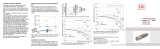
2.3 Structure of the Complete Measuring System
The eddyNCDT 306x non-contact single chan-
nel displacement measuring system consits of
- Sensor
- Sensor cable
- Connection cable
- Controller
i
The components are matched to one
another. The allocation of the sensor and
the controller is determined by the serial
number.
Fig. 1 eddyNCDT 306x with controller and
sensors

Page 11
Functional Principle, Technical Data
eddyNCDT 306x
2.4 Glossary, Analog Output Displacement
SMR
Sensor
20 mA
12 mA
4 mA
Target
Measuring range (MR)
SMR MMR EMR
Displace-
ment
10 V
5 V
0 V
Signal
SMR Start of measuring range
Minimum distance between sensor front and measuring object, sensor specific
MMR Mid of measuring range
EMR End of measuring range (Start of measuring range + measuring range) Maxi-
mum distance between sensor front and measuring object
MR Measuring range

Page 12
Functional Principle, Technical Data
eddyNCDT 306x
2.5 Technical Data
Sensor
ES-U1 ES-S2 ES-U3 ES-S4
Measuring range 1 mm 2 mm 3 mm
4 mm
Start of measuring range 0.1 mm 0.2 mm 0.3 mm 0.4 mm
End of measuring range 1.1 mm 2.2 mm 3.3 mm 4.4 mm
Resolution
2,3
static (20 Hz) 0.02 µm 0.04 µm 0.06 µm 0.08 µm
dynamic (20kHz)
0.1
µm
0.2
µm
0.3
µm
0.4
µm
Frequency response
selectable 20 kHz, 5 kHz, 20 Hz
Measuring rate
50 kSa/s
Linearity
3-point linearization ≤ ± 2 µm ≤ ± 4 µm ≤ ± 6 µm ≤ ± 8 µm
5-point linearization
1
≤ ± 1 µm ≤ ± 2 µm ≤ ± 3 µm ≤ ± 4 µm
Temperature stability
sensors
2
≤ 0.15 µm / K ≤ 0.3 µm / K ≤ 0.45 µm / K ≤ 0.6 µm / K
controller ≤ 0.015 % d.M. / K
Temperature compensation
sensors +10 … +180 °C
(+50 ... +356 °F)
controller +10 … +50 °C
(+50 ... +122 °F)
Target material ferromagnetic, non-ferromagnetic
Minimum target size (flat) operation
ø18 mm ø36 mm ø27 mm
Sensor type
unshielded shielded unshielded shielded
Temperature
range
sensors
operation
-20 … +180 °C
(-4 ... +356 °F)
-20 … +200 °C
(-4 ... +392 °F)
storage
-50 … +180 °C
(-58 ... +356 °F)
-50 … +200 °C
(-58 ... +392 °F)
controller
operation
0 … +50 °C (+32 ... +122 °F)
storage
-10 … +70 °C (+14 ... +158 °F)
Supply voltage (power consumption)
12
…
32 VDC (2.5 W)
Pressure resistance
front
20 bar
rear
5 bar

Page 13
Functional Principle, Technical Data
eddyNCDT 306x
Sensor
ES-U1 ES-S2 ES-U3
ES-S4
Analog output
0 … 10 V (short circuit proof); 4 … 20 mA (load max. 500 Ohm)
Weight sensors (without nuts)
2,4 g 11 g 12 g 30 g
controller
ca. 230 g
Shock (DIN-EN 60068-2-29)
15 g / 6 ms in 3 axes, 2 directions and 1000 shocks each
Vibration (DIN-EN 60068-2-6)
5 g / 10 ... 500 Hz in 3 axes, 2 directions and 10 cycles each
Protection class (DIN-EN 60529)
sensors
IP68 (plugged)
controller
IP67 (plugged)
FSO = Full Scale Output
1) Valid for operation with DT3061 controller
2) Relates to mid of measuring range
3) RMS value of the signal noise

Page 14
Delivery
eddyNCDT 306x
3. Delivery
3.1 Unpacking, Included in Delivery
1 Sensor incl. sensor cable
1 Controller
1 Test log
1 Quick manual
1 PC3/8-M12 (analog output/ power supply)
1 SCD2/4/RJ45 Ethernet adapter cable
Carefully remove the components of the measuring system from the packaging and ensure that the
goods are forwarded in such a way that no damage can occur.
Check the delivery for completeness and shipping damage immediately after unpacking.
If there is damage or parts are missing, immediately contact the manufacturer or supplier.
You will find optional accessories in appendix, see Chap. A 1.
3.2 Storage
- Temperature range storage:
Sensors: -50 ... +180 °C (-58 ... +356 °F), valid for sensor ES-U1
-50 ... +200 °C (-58 ... +392 °F), valid for standard sensors
Controller: -10 ... +70 °C (+14 ... +158 °F)
- Humidity: 5 - 95 % (non condensing)

Page 15
Installation and Assembly
eddyNCDT 306x
4. Installation and Assembly
4.1 General
No sharp or heavy objects should be allowed to affect the cable sheath of the sensor cable, the supply cable
and the output cable.
i
A damaged cable cannot be repaired. Tension on the cable is not permitted!
4.1.1 Model
The eddyNCDT measuring system will be used with unshielded or shielded sensors.
Unshielded sensors
- Type designation: ES-Ux
- Construction: The sensor cap with encapsulated coil consists of electrically
non-conducting materials.
i
In the radial direction metal parts in the vicinity may behave similar to the
measuring object, rendering the measurement result inaccurate. Please
note this by selection of material for sensor mounting and their setup.
Fig. 2 Unshielded sensor
Shielded sensors
- Type designation: ES-Sx
- Construction: The sensor enclosed up to its front face with a steel housing
with a mounting thread. With it the sensor is shielded from interference
through radially near located metal parts.
Fig. 3 Shielded sensor

Page 16
Installation and Assembly
eddyNCDT 306x
4.1.2 Start of Measuring Range
SMR
Sensor
Target
Measuring range (MR)
Fig. 4 Start of measuring range (SMR), the minimum distance between sensor face and target
For each sensor a minimum distance to the measuring object must be maintained.
This avoids a measurement uncertainty due to the sensor pressing on the measuring object and mechanical
damage to the sensor/target.
Eddy current displacement sensors can be affected in their measurement properties by a metallic holder.
Depending on the sensor type, the following sensor mounting should be preferred:
- unshielded sensors: Standard mounting
- shielded sensors: Flush mounting

Page 17
Installation and Assembly
eddyNCDT 306x
4.2 Installation Scenario Sensor
4.2.1 Standard Mounting
The sensors protrude beyond the metal holder.
The installation scenario depicted is used for factory calibration of the
sensors at Micro-Epsilon.
The technical sensor data correspond to standard installation conditions.
If you want to achieve the values indicated in the data sheet, we recom-
mend to install the sensor in the same way as it was during calibration.
Sensors with a thread
Insert the sensor through the hole in the sensor holder.
Screw the sensor tight.
Turn the mounting nuts from the delivery on both sides on the thread protruding from the holder.
Tighten the mounting nuts carefully to avoid damage, particularly to smaller sensors.
i
Prefer the standard mounting of the sensor, because the optimum measurement results can be achieved with this method!
Holder
Mounting
nuts
Sensor
Sensor
cable
A
Sensor ES-U1 ES-U3
A
Sensor ES-S2 ES-S4
Dimension A 8 mm 10 mm Dimension A 4 mm 4 mm
Fig. 5 Unshielded sensor with thread in standard mounting Fig. 6 Shielded sensor with thread in standard mounting
i
During calibration maintain the same relative position of the sensor to the holder as for the measurement!

Page 18
Installation and Assembly
eddyNCDT 306x
4.2.2 Flush Mounting
Flush mounting does not correspond to factory calibration.
Micro-Epsilon recommends to carry out at least a 3-point
field linearization.
i
Linearize the measuring system, if possible, when it is
exactly arranged (in the same way as it will be arranged
later during the measurement process).
Sensors with a thread
Mount shielded or unshielded sensors flush in a sensor holder of insulating material (plastic, ceramic, et cetera).
Mount the shielded sensors flush in a metal sensor holder, see Fig. 8.
Mount unshielded sensors flush in a metal sensor holder, see Fig. 7. Make sure that a recess of a size three times the sensor
diameter is used.
In all mounting cases screw the sensor into the threaded hole and lock it with the mounting nut.
Tighten carefully to avoid damage, particularly to smaller sensors.
i
Calibrate the measuring system in the measuring setup with actual mounted sensor.
≥ 3 x Sensor
diameter
Holder
Mounting
nut
Sensor
Sensor
cable
Fig. 7 Flush mounting of an unshielded sensor in a metal holder Fig. 8 Flush mounting of a shielded sensor in a metal holder

Page 19
Installation and Assembly
eddyNCDT 306x
4.3 Measurement Setup, Operating Multiple Sensors
Sensors of the eddyNCDT 306x series cannot be synchronized. Observe the following installation information regarding the minimum
distance between two sensors:
- 3x sensor diameter distance between two unshielded sensors with equal carrier frequency (e. g. low frequency)
- 1.5x sensor diameter distance between two shielded sensors with equal carrier frequency (e. g. low frequency)
- two nearby mounted sensors only as low frequency and high frequency models
low frequency
high frequency
Target
low frequency
ES-Ux
low frequency
Target
min 3 x
sensor dia.
Target
low frequencyhigh frequency
low frequency high frequency
low frequency
low frequency
Target
low frequency
ES-Sx
low frequency
Target
min 1.5 x
sensor dia.
high frequency
high frequency
Target
Sensor, ES-Ux
Sensor, ES-Sx
No synchronization required Not possible

Page 20
Installation and Assembly
eddyNCDT 306x
4.4 Dimensional Drawings Sensors
ø4.5
M6x0.5
4
22
ø4.7
ca. 36 (1.42)
ca. 100 (3.94)20
ca. 8 Cable length x
ø9
8
SW10
3.2
ø3.6
ø4.5
ca.26 (1.02)
(.18)
(.18)
(.35)
(.19)
(.14)
(.13)
(.31)
(.16)
(.31)
(.87)
(.79)
Fig. 9 Dimensional drawing sensors ES-U1-C-CAx/mB0, dimensions in mm (inches)
ø3.6
(.14)
ca.100 (3.94)
20 (.79)
Cable length x
M12x1
SW19
SW10
25 (.98)
ca. 36 (1.42)
ø4.5
4 (.16)
ca. 8
6
ca. 26 (1.02)
ø9
(.18)
(.35)
(.24)
(.31)
Fig. 10 Dimensional drawing sensors ES-S2-C-CAx/mB0, dimensions in mm (inches)
/