Page is loading ...

Assembly Instructions
optoNCDT 1700
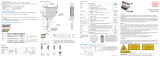
Proper Use
The optoNCDT1700 is designed for use in industrial areas. It is used for measuring displacement,
distance, position and elongation for in-process quality control and dimensional testing.
The sensor may only be operated within the limits specified in the technical data, see instruction
manual, Chap. 3.4. The sensor should only be used in such a way that in case of malfunctions or
failure personnel or machinery are not endangered. Additional precautions for safety and damage
prevention must be taken for safety-related applications.
Warnings
Connect the power supply in accordance to the safety regulations for electrical equipment. The
power supply may not exceed the specified limits.
> Danger of injury, damage to or destruction of the sensor
Avoid continuous exposure to spray on the sensor. Avoid exposure to aggressive materials (washing
agent, penetrating liquids or similar) on the sensor.
> Damage to or destruction of the sensor
Avoid shock and vibration to the sensor. Protect sensor cable against damage.
> Damage to or destruction of the system, failure of the measuring device
Laser Class
The optoNCDT1700 sensors operate with a semiconductor laser with a wavelength of 670 nm (visi-
ble/red, ILD 1700) respectively 405 nm (visible/blue, ILD 1700BL).
The following warning labels are attached to the cover (front and/or rear side) of the sensor housing:
LASER RADIATION
Do not stare into the beam
CLASS 2 LASER PRODUCT
IEC 60825-1: 2008-05
P≤1 mW; � λ= 670 nm
LASER RADIATION
Do not stare into the beam
CLASS 2 LASER PRODUCT
IEC 60825-1: 2008-05
P≤1 mW; λ= 405 nm
IEC label Only for USA IEC label for ILD1700-x BL only
Never deliberately look into the laser beam! Consciously close your eyes or
turn away immediately if ever the laser beam should hit your eyes.
Inputs and Outputs
Pin Designation Comment Sensor cable
PC1700-x
5 +U B Power supply (11 ... 30 VDC) red
6 GND
System ground for power supply and
switching signals (Laser on/off, Zero,
Limits)
black
13 Analog output Current 4 ... 20 mA or
voltage 0 ... 10 V Coaxial inner conductor, white
14 AGND Reference potential for analog output Coaxial screening
9 Laser on/off Switching input laser on /off red-blue
10 Zero Switching input setting mid-point white-green
8Switching output 1 Error or limit output gray-pink
7Switching output 2 Limit output violet
3
4
Sync + 1
Sync - 1
Symmetrical synchron output
(Master) or input (Slave)
blue
pink
1
2
Tx +
Tx - RS422 - output (symmetrical) green
brown
12
11
Rx +
Rx - RS422 - input (symmetrical) gray
yellow
1) Used as trigger inputs in mode „Triggering“.
Plug connector: ODU MINI-SNAP, 14-pin, series B, dimension 2,
code 0, IP 68; www.odu.de
View on solder-pin side male cable connector, insulator
1
2
3
4
56
7
8
9
10
11
12
13
14
Power Supply, nominal value: 24 VDC (11 ... 30 V, max. 150 mA).
ILD 1700
5
6
11 ...
30 VDC
Sensor
pin
PC1700-x
color
Power
supply Use power supply only for measurement
devices. MICRO-EPSILON recommends
the use of the optional available power
supply PS2020 for the sensor.
5 red +UB
6 black GND
Switching Inputs Laser On/Off, Setting Masters and Mid-point
ILD 1700 U
N-channel Relais/
switch
9 (10)
6
Open-
Collector
int
UL
U 0.2 V
L
I 0.5 mA
L
IL
X9771139-A051095HDR
MICRO-EPSILON MESSTECHNIK
GmbH & Co. KG
Königbacher Str. 15 · 94496 Ortenburg
www.micro-epsilon.com
*X9771139-A05*
The switching inputs for laser on/off and
setting masters/mid-point are similarly
wired. Connect pin 9 with pin 6 in order
to activate the laser. If the connection is
released, the laser is deactivated.
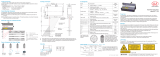
Membrane Keys, LED‘s
Measurement mode (normal operation):
- zero key:
Sets the analog output to the value for the midrange, i.e. 5 VDC or
12 mA.
Pressing the zero key again resets the function.
- function key:
Switches the sensor to setup mode.
Pressing and holding the function/enter key for longer than 5 se-
conds, overwrites all the parameter values with the factory settings (default
values).
Setup mode (function key actuated):
- function key:
For running through the levels and parameters.
- select key:
To open the selection list and
select the value of the parameter in sequence.
- enter key:
For saving the selected parameter value and
returning to measurement mode.
If approximately 15 seconds have elapsed since the last press of the function key or
30 seconds since the last press of the select key, the sensor returns to measurement mode
without changing the parameters.
LED Status Measurement mode Setup mode
state
illuminated Object is in the measurement
range or error ...
off Sensor off or laser off
flashes slowly ... Selected parameter value matches the
saved value
flashes quickly ... Selected parameter value does not
match the saved value
output
speed
avg
illuminated or
flashing
Indication of the parameter values
level 1 Selected parameter value
flashing red Status „off“
zero
illuminated Sensor „master“ or „set to mid-point“
off Normal operation
flashing Sensor as slave without synchronous signal
In case of bore holes, blind holes and
edges in the surface of moving targets
the sensor must be arranged in such a
way that the edges do not obscure the
laser spot.
Correct Incorrect
(shadow)
Dimensional Drawing and Free Space,
Measuring Ranges 2/10/20/50/100/200/250VT mm
Measuring Ranges 20/200BL
ILD 1700-2/10/20/50/100/200/250VT
ILD1700-2/10/20/50LL
ILD 1700-20/200BL
A
B
ø 4
(dia .16)
ø 8
(.31 dia)
15
(.59)
SMRMR
80 (3.15)
89 (3.50)
97 (3.82)
30
(1.18)
15
(.59)
24.2
(.95)
36.1
(1.42)
67 (2.63)
4
75 (2.95)
37.5
(1.48)
Mounting holes
3 x ø4.5 (.18 dia.)
13.4 (.53)
13.2
(.52)
MR = Measuring range
SMR = Start of measuring range
MMR = Midrange
EMR = End of measuring range
MR SMR a e A B
2 24 35.0 ° 44.8 ° 25.8 16.8
10 30 34.3 ° 35.6 ° 28.7 20.5
20 40 28.8 ° 26.7 ° 30.1 22.0
50 45 26.5 ° 18.3 ° 31.5 22.5
100 70 19.0 ° 10.9 ° 32.6 24.1
200 70 19.0 ° 7.0 ° 33.1 24.1
250VT 70 19.0 ° 6.0 ° 33.5 24.1
20BL 40 28.8 ° 26.7 ° 30.1 22.0
200BL 100 13.5 ° 6.3 ° 33.1 24.1
Proper Environment
- Protection class: IP 65 (only with sensor cable connected)
Lenses are excluded from protection class. Contamination of the lenses leads to impairment or
failure of the function.
- Operating temperature: 0 ... 50 °C (+32 up to +122 °F)
- Storage temperature: -20 ... 70 °C (-4 up to +158 °F)
- Humidity: 5 - 95 % (no condensation)
- Ambient pressure: Atmospheric pressure
Sensor Mounting
The sensors of the series optoN-
CDT 1700 are optical sensors
with which is measured in the μm
area.
iMake sure that mounting
and operation is handled
carefully!
Mount the sensors with
three screws type M4. The
bearing surfaces surround-
ing the fastening holes
(through holes) are slightly
raised.
Dimensions in mm (inches), not to scale

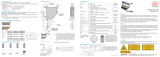
Quick Guide
Components, Typical Application with Analog Output
PC1700-x
Target
PS2020
SPS
230 VAC
PE
N L
A
D
4 ... 20 mA
0 ... 10 V
Laser On/O
laser off
error
o.k.
midrange
normal
zero
4 - 20 mA
0 - 10 V
RS 422
1
1/2
1/4
1/8
1
4
32
128
optoNCDT
Components, Typical Application with RS422 and IF2008
PC1700-x/IF2008
Target
laser off
error
o.k.
midrange
normal
zero
4 - 20 mA
0 - 10 V
RS 422
1
1/2
1/4
1/8
1
4
32
128
optoNCDT
IF2008
Switching on the Power Supply Respectively PC
Switch on power supply respectively PC after completion of wiring.
The initialization including the info string transmission takes up to 10 seconds. Within this period,
the sensor neither executes nor replies commands.
To be able to produce reproducible measurements the sensor typically requires a start-up time of
20 minutes.
Change Measurement Value Output
Change the output type with the function/enter and select/zero keys.
Measurement
mode
Current output
4 ... 20 mA
Voltage output
0 ... 10 VDC RS422
LED state
flashes green
red (flashes)
LED output red green
Save
parameters
function
enter
select
zero select
zero select
zero select
zero
function
enter
Measurement value
mode
Place Target
Place the target in the midrange, if possible.
SMR
Target
Measuring range (MR)
Digital value
20 mA
4 mA
3 mA
Analog
output
1610
16372 16207 16367 16374
MBA EMR
Displacement
10.2 V
10 V
0 V
-0.1 V
laser off
error
o.k.
midrange
normal
zero
4 - 20 mA
0 - 10 V
RS 422
1
1/2
1/4
1/8
1
4
32
128
optoNCDT
The State LED on sensor indicates the position of target to the sensor.
LED Color Meaning
State
off Laser beam is switched off.
green Sensor in operation, target in measuring range
yellow Target is in midrange.
red Target out of range, too low reflection
Operating Mode
Change the operating mode of the sensor.
Error-Mode (error control, factory setting)
Switching output 1 Switching output 2
Measurement value
EMR
+
GND
+
GND
Switching output 1
Switching output 2
SMR
Time
Error output inactive
The switching output 1 is activated
(conducting to GND),
- when the target is outside the
measuring range,
- there is no target present
- or if the target is unsuitable (too
dark, polished metal, insufficiently
reflective).
Function
- Setting mid-point
- No limit control
Switch-Mode (limit control)
Switching output 1 Switching output 2
Measurement value
UL
UH
LH
LL
+
GND
+
GND
+
GND
+
GND
Switching output 1
Switching output 2
Switching output 1
Switching output 2
SET_UPPERLIMIT F1
SET_LOWERLIMIT F1
EMR
SMR
Time
Limit value Limit value
The switching outputs are activated
(conducting to GND),
- when the target is outside the
measuring range,
- there is no target present
- or if a target is unsuitable (too
dark, polished metal, insufficiently
reflective).
The following 4 values are used:
- Upper limit (UL), --
- Lower limit (LL), --
- Upper hysteresis value (UH), --
- Lower hysteresis value (LH).
Function
- Mastering
- Limit control
Please refer to the instruction manual for factory settings to the limit and hysteresis values.
Switching Outputs
+24 VDC
T
ILD1700
Switching output 1/2
Pin 7 / 8
GND Pin 6
max. 100 mA
+U Pin 5
BThe transistor T is conductive in the
active state. The switching outputs are
short-circuit-proof.
To reset the short-circuit protection:
- Clear the external short circuit,
- switch off the sensor and switch on
again or
- send the software command „Reset“
to the sensor.
The two limit outputs may also be actu-
ated in parallel as window comparator
(OK/Not OK separation).
You will find informations on display and signal processing units online at: www.micro-epsilon.
com/accessories/index.html.
You can read more information about the sensor in the instruction manual. You will find these on-
line at www.micro-epsilon.de/download/manuals/man--optoNCDT-1700--en.pdf or on the delivered
CD.
- Power supply sensor
- Synchronization sensors
- Laser on/off
is done by the interface card
/