Page is loading ...

OPERATING INSTRUCTION
-1-1
FEATURES
230
Power Supply Unit (the Unit hereinafter) is a two-channel power source with regulated output voltages
and , and common ground terminals .
The Unit is intended for operation within video doorphones. The output is used to power an outdoor camera,
the output supplies power to a group of video monitors with no built-in power source.
Over-current, short-circuit, over-heat protection
Power LED indicators
The unit
gthethe ,
The mains plug shall remain readily operable.
BPD24/12
+24 VDC +12 VDC GND
VIZIT +12V
+24V VIZIT
PARTS LIST
SAFETY INSTRUCTIONS
WARNING! Vcontains dangerous for life high voltage - .
Unplu the unit before replacing fuse and connecting wires.To avoid damage or electric shock do not make any
repair when the power is on.
No metallic objects shall penetrate into ventilation openings of the unit. The unit shall not be exposed to dripping or
splashing and no objects filled with liquids shall be placed on the unit.
·
·
BPD24/12-1-1
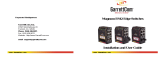
(1) Holes for screws
(2) Mains cord
(3) 12VDC output voltage LED
(4) Holder for fixing the Unit on a DIN-rail
(5) 12VDC and 24VDC output voltage terminals
(6) 24VDC output voltage LED
Power Supply Unit BPD24/12-1-1 appearance
www. 5BPD24/12-1-1 Operating Instruction (revision 12)vizit-group.com 21/201 -
2
11
3
+12V +24V
GND
4 5 6
Operating Instruction
x1
x1
Power Supply Unit
Fasteners
Screw 4 40-х Anchor 4- 6х 0
x 4 x 4
x 1
Fuse T200AL

INSTALLATION
VIZIT
Output terminals shall be oriented horizontally.
G! U Make sure that no objects prevent proper
ventilation of the Unit, and the Unit’s ventilation openings are not covered or blocked.
Terminals names and destinations
SPECIFICATIONS
V ± VDC
V, . A
1 V ± . VDC
12V, . A
mV
230 ± 23 VAC
W
mm
.kg
OPERATING CONDITIONS
The Unit shall be installed in heated premises with sufficient ventilation and securely fixed to a wall or inside the
Mounting Box
The Unit is fixed either with a springing clip to a DIN-rail (35 mm x 1-2 mm), or with screws (supplied).
Cables are connected to the Unit’s output terminals.
Output voltage at
Output load current at max.
Output voltage at
Output load current at max.
Ripple voltage, max.
Input voltage range at 50Hz
Power consumption, max.
Dimensions (W)x(H)x(D) x x
Weight
Ambient temperature range to
Relative humidity of air up to at
,
.
Such conditions provide proper ventilation of the unit.
+
+
WARNIN Do not mount the nit near heating equipment!
+24 24 2
+24 0 8
+ 2 12 0 6
+0 3
10
30
165 90 60
1 1
+1°С +40°С
93% +25°С
CONNECTIONS
For qualified installation, wiring and servicing refer to technical and commercial partners of VIZIT TM. The list
of companies is given on VIZIT.EU ( .http://vizit.eu/eurounion/)
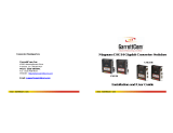
- Drill 4 holes (1) in a wall, with diameter 6 mm and depth 40 mm
- Drive anchors (2) into the holes
Attach the Unit to the wall and fasten 4 screws
in the anchors
Note. Anchors and screws are supplied
.
.
- (3)
.
.
( ) Bosses on the Unit’s base
( ) rail with width mm and
depth mm
( ) Holder for fixing
1-
2 - DI - 35
1-2
3-
N
BPD24/12-1-1 mounting on a railDIN-BPD24/12-1-1 mounting on a wall
12
3
1
2
3
Destination
Terminal
12VDC output voltage
+12V
GND
24VDC output voltage
GND
+24V
+12V +24VGND
www. 5BPD24/12-1-1 Operating Instruction (revision 12)vizit-group.com 2 2/201 -
/