Page is loading ...

Manual No.
BFV-OM3-8
Val-Matic
®
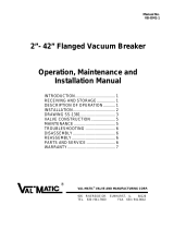
3"-24" Butterfly Valve
With LSA Actuator and
External Stops
Operation, Maintenance and
Installation Manual
INTRODUCTION ........................................ 2
RECEIVING AND STORAGE ..................... 2
DESCRIPTION OF OPERATION ............... 2
VALVE CONSTRUCTION .......................... 3
INSTALLATION .......................................... 4
MAINTENANCE .......................................... 7
TROUBLESHOOTING ................................ 10
DISASSEMBLY .......................................... 10
REASSEMBLY ........................................... 11
SEAT RELACEMENT ................................. 11
PARTS & SERVICE .................................... 12
WARRANTY ............................................... 12
VAL-MATIC
®
VALVE AND MANUFACTURING CORP.
905 Riverside Dr. ● Elmhurst, IL 60126
Phone (630) 941-7600 ● Fax (630) 941-8042
www.valmatic.com

2
VAL-MATIC'S 3"-24" SERIES 2000 BUTTERFLY VALVE
OPERATION, MAINTENANCE AND INSTALLATION
INTRODUCTION
The Series 2000 Butterfly Valve has been designed
to give years of trouble-free operation. This manual
will provide you with the information to properly install
and maintain the valve to ensure a long service life.
The valve is a resilient seated, quarter-turn valve
capable of handling air, water, or other clean fluids.
For fluids with suspended solids, a Model 5800R
Eccentric Plug Valve should be used. The Size, Cold
Working Pressure (CWP), and Model No. are
stamped on the nameplate for reference.
The "Cold Working Pressure" is the non-shock
pressure rating of the valve at 150oF. The valve is not
intended as a block valve for line testing above the
valve rating. The valve is intended for flow toward the
seat end of the valve. The typical flow direction and
“Seat End” are marked on the nameplate. This allows
seat adjustment while the valve is holding system
pressure.
RECEIVING AND STORAGE
Inspect valves upon receipt for damage in shipment.
Unload all valves carefully to the ground without
dropping. Do not lift valves with slings or chains
around the actuator or through the seat area. Extra
care must be taken when handling electric motor and
cylinder actuated valves.
Valves should remain crated, clean and dry until
installed to prevent weather related damage. For long
term storage greater than six months, indoor storage
is recommended. The valve flange covers must
remain in place, the valve must remain slightly open
(3-5 degrees), and the rubber surfaces of the disc
should be coated with a thin film of FDA approved
grease such as Dow Corning # 7. Do not expose the
resilient seat to sunlight or ozone for any extended
period. Electric actuators must be powered if stored
outdoors or in cool areas so that the internal heaters
will prevent condensation in the control unit.
DESCRIPTION OF OPERATION
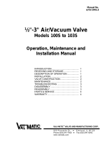
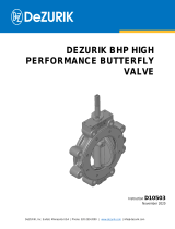
As shown in Figure 1, the valve consists of a body, a
disc, and a shaft that rotates in body bearings. The
resilient seat provides drop-tight shutoff.
FIGURE 1. BUTTERFLY VALVE WITH ACTUATOR
The disc is rigidly attached to the shaft with taper pins.
The actuator rotates the valve shaft and disc through
90 degrees of operation. The disc can rotate through
the seat, but is factory set to stop in the center of the
seat to provide tight shut off. Additional torque on the
actuator when against the closed stop of the actuator
will not provide tighter shut off. The valve seat is
easily adjustable or replaceable should wear or
damage occur over time.
The valve can be operated with a hand lever or gear
actuator. The gear actuator as shown in Figure 1
requires multi-turn input on a 2" square nut,
handwheel, or chainwheel. The valve can also be
automated with power actuators such as an electric
motor or hydraulic cylinder.

3
VALVE CONSTRUCTION
The standard Series 2000 Butterfly Valve is
constructed of rugged cast iron with a stainless steel
shaft and resilient disc edge. See the specific
Materials List submitted for the order if other than
standard cast iron construction. The details of
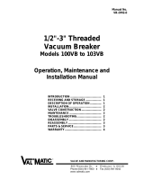
construction are illustrated in Figure 2.
The body (1) is available with flanged or mechanical
joint ends for connection to the pipeline. The body is
equipped with a stainless steel seat (2). The 1/4 turn
disc (3) is guided by a stainless steel shaft (4) which
rotates in non-metallic bearings (5) fixed in the body.
Leak-tight closure is made when the resilient seat (6)
is rotated into the stainless steel seat on the "SEAT
END" of the body.
Table 1. Standard Valve Parts List
Item Description Material
1Bod
y
Gra
y
or Ductile Iron
2Bod
y
Sea
t
Stainless Steel
3 Disc Ductile Iron
4 Shaft Stainless Steel
5 Sleeve Bearin
g
* N
y
latron
6 Resilient Seat* Buna-N
7 Seat Retainin
g
Rin
g
Stainless Steel
8 Ret. Rin
g
Screws* Stainless Steel
9 Taper Pin Stainless Steel
10 Taper Pin O-Rin
g
* Buna-N
11 Taper Pin Nut Stainless Steel
12 Taper Pin Washer Stainless Steel
13 Packin
g
* Buna-N
14 Ke
y
Carbon Steel
15 Thrust Bearin
g
Cap Ductile Iron
16 Cap Screws Carbon Steel, Plated
18 Thrust Plate Bronze
24 Bod
y
O-Rin
g
Buna-N
FIGURE 2. STANDARD BUTTERFLY VALVE CONSTRUCTION

4
INSTALLATION
The installation of the valve is important for its proper
operation. Some general recommendations follow.
Some specific piping problems are also shown in the
figures to the right.
WATER SERVICE: The normal flow direction is
towards the seat end of the valve. When the flow
stops, the return pressure will be held by the closed
disc and the seat bolts (8) can be adjusted to provide
tight shut off should the seat be worn or damaged.
The normal flow direction and the words "SEAT END"
are marked on the nameplate which is located on the
seat end valve flange.
AIR AND GAS SERVICE: Install valve with pressure
toward the end opposite the seat end. Lubricate
resilient seat with FDA approved silicone grease such
as Dow Corning #7 before installation. Gear actuators
are recommended for gas service applications.
PUMP DISCHARGE SERVICE: On all horizontal
pump discharge applications (Figure 3), the seat end
should be towards the pump to allow seat adjustment
with system pressure against the disc. The valve shaft
should be oriented parallel to the plane of the pump
discharge elbow (i.e. vertical valve shaft on a vertical
discharge elbow). If the butterfly valve is downstream
of a check valve, the clearance between the two discs
must be checked. The butterfly valve shaft should be
oriented as shown in Figure 4.
BURIED SERVICE: The valve should be installed
with the shaft horizontal and the actuator nut directed
upwards (Figure 4). The valve box or extension pipe
should be installed so that the actuator nut and
extension stem turn freely.
150B flanged valves should be mated to ANSI Class
125# flat-faced flanges equipped with resilient
gaskets. When ring gaskets are used, the bolt
material shall be ASTM A307 Grade B or SAE Grade
2 Carbon Steel. Higher strength bolts may only be
used with full-face gaskets.
Some of the flange holes are tapped near the shaft
ends of the valve as shown on the Sales Drawing.
Special bolt lengths may be needed. An engagement
of at least one bolt diameter is typically used for the
flange bolts used in the tapped flange holes.
AWWA Class 250B flanged valves can be mated with
either ANSI Class 125# or ANSI Class 250# flanges
depending on the specified flange drilling. Class 250B
valves can be mated with flat-faced or raised-face
flanges with full face or ring gaskets and with no
bolting restrictions.
FIGURE 3. PUMP DISCHARGE
FIGURE 4. UPSTREAM CHECK VALVE
Table 2. Minimum Pipe I.D. to Clear
Flan
g
ed BF
V
Size Min. I.D. Size Min.I.D.
3” --- 14” 11.7
4” --- 16” 14.0
6” 3.75 18” 16.4
8” 5.10 20” 18.5
10” 6.70 24” 22.8
12” 9.50
Table 3. Minimum Pipe I.D. to Clear
Mechanical Joint BF
V
Size Min. I.D. Size Min.I.D.
4” 3.12” 14” 12.75”
6” 5.26” 16” 14.44”
8” 7.31” 18” 16.58”
10” 9.25” 20” 18.75”
12” 10.93” 24” 22.44”
CAUTION
The valve interior seating surfaces must be
free of debris and construction materials.

5
INSTALLATION (Cont'd)
In all installations, the valve and adjacent piping must
be supported and aligned to prevent cantilevered
stresses on the valve. Lower valve into line using
slings or chains around the valve body. Lubricate the
flange bolts or studs and insert them around the
flange. Lightly turn bolts until gaps are eliminated.
The torquing of the bolts should then be done in
graduated steps using the cross-over tightening
method. If leakage occurs, allow gaskets to absorb
fluid and check torque and leakage after 24 hours. Do
not exceed bolt rating or crush gasket more than 50
percent of its thickness; see tables below.
Table 4. Flange & MJ Nut Torques
150B Flange Bolt Torques
Valve
Size (in)
Bolt Dia
(in)
Recom
Torque
(
ft-lbs
)
Max
Torque
(
ft-lbs
)
3,4 5/8 25 100
6 3/4 30 150
8 3/4 40 150
10 7/8 45 200
12 7/8 65 200
14 1 80 300
16 1 90 300
18 1 1/8 100 425
20 1 1/8 120 425
24 1 1/4 150 600
250B Flange Bolt Torques
Valve
Size (in)
Bolt Dia
(in)
Recom
Torque
(
ft-lbs
)
Max
Torque
(
ft-lbs
)
4,6 5/8 30 150
8 7/8 50 200
10 1 75 300
12 1 1/8 100 425
14 1 1/8 100 425
16 1 1/4 150 600
18 1 1/4 150 600
20 1 1/4 200 600
24 1 1/4 300 1000
Mechanical Joint Bolt Torques
Valve
Size (in)
Bolt Dia
(in)
Recom
Torque
(
ft-lbs
)
Max
Torque
(
ft-lbs
)
43/475 90
63/475 90
83/475 90
10 3/4 75 90
12 3/4 75 90
14 3/4 75 90
16 3/4 75 90
18 3/4 75 90
20 3/4 75 90
24 3/4 75 90
MECHANICAL JOINT ENDS: Clean ends of mating
pipe and valve sockets with soapy water (Figure 5).
Place lubricated gasket and retainer gland over pipe
end prior to installing valve. Install valve socket over
pipe. Press gland and gasket toward valve until
gasket is evenly set into valve socket.
FIGURE 5. MECHANICAL JOINT INSTALLATION
Insert T-bolts in valve flange and hand tighten nuts.
Torque nuts in four graduated steps using the cross-
over tightening method without exceeding the torque
listed in Table 4. Maintain an equal gap between the
gland and the face of the valve at all points around
the socket.
If a tight connection is not achieved, then the joint
should be disassembled, thoroughly cleaned, and
reassembled. Over-tightening, may cause damage to
the valve or gland.
CAUTION
The use of raised-face flanges or excessive
bolt torque may damage valve flanges.

6
LEVER OPERATED VALVES: 8" and smaller valves
may be equipped with a top-mounted lever for direct
quarter-turn operation. To open the valve, slowly
rotate the lever 90° in the counter-clockwise CCW
direction.
FIGURE 6. LEVER ACTUATOR
Valve
Size
Pressure
(
PSI
)
Model
Number
L
(
Inches
)
3”-4” 150 4BL 12
6” 150 6BL 12
8” 75 6BL 12
10” 75 10BL 18
12” 75 10BL 18
GEAR OPERATED VALVES: Butterfly Valves are
available with a two types of manual gear actuator.
A worm gear actuator has a multi-turn worm that
drives a large sector gear through 90 degrees of
rotation. Worm gears provide uniform motion and
torque multiplication throughout the stroke.
A traveling nut actuator has a threaded rod that
drives a nut from one end of the housing to another.
The traveling nut in turn drives a slotted lever through
90 degrees of rotation. Traveling nut actuators
provide slower rotation and greater torque
multiplication at the ends of travel.
Both gear types are self-locking and multiply the
turning force on the handwheel or nut so that valves
can be operated with ease. A clamp-on chainwheel
kit can also be used for installations high above the
floor. An indicator on the top of the actuator housing
indicates the position of the valve plug. The
handwheel or nut must be rotated through 7-50 turns
(depending on model) to open or close the butterfly
valve. The direction of rotation to open the valve is
indicated on the 2" square actuator nut and
handwheel. The standard direction of rotation is open
left or counter-clockwise. Nuts with opposite rotation
(open right) will be painted red to indicate their special
rotation.
GEAR ACTUATOR ADJUSTMENT: The standard
gear actuator is provided with factory-set open and
closed position stops to properly center the closed
disc seal in the body seat. No field adjustment is
necessary.
VALVE SEAT ADJUSTMENT: If the valve is found to
leak in service, the rubber seat can be adjusted. With
the valve in the closed position, tighten the three seat
bolts in the area of the leak 1/4 turn at a time until the
leak stops.
The initial factory settings for the seat bolts are given
in Table 5 for reference in case the valve cannot be
tested while under pressure. These torques are for
use with the disc in the closed position at the time of
seat installation. Torques greater than 150% of these
will make the valve difficult to operate.
Elastomer seats will naturally relax over time.
Measured seat bolts torques will often be less than
initial seat bolt torques listed herein. Never tighten
seat bolts unless the disc is in the closed position.
Table 5. Initial Seat Bolt Torques
Sizes Class 150B Class 250B
3”-8” 5 ft-lbs 7 ft-lbs
10”-20” 10 ft-lbs 12 ft-lbs
24” 15 ft-lbs 17 ft-lbs
FIGURE 7. WORM GEAR ACTUATOR
FIGURE 8. TRAVELING NUT ACTUATOR
CAUTION
Fill LSA Actuators with at least 90% grease
prior to mounting electric motor actuators.

7
MAINTENANCE
For water service, the Series 2000 Butterfly Valve
requires no scheduled lubrication or maintenance
other than regular exercising. The exercising is
achieved by fully opening and closing the valve to
verify smooth operation. If operation is difficult, it may
be necessary to flush sediment from the valve by
opening and closing the valve several times under
flowing conditions or checking the lubricant in the
gear actuator. For valves in air service, apply a thin
film of FDA silicone grease such as Dow Corning #7
to the exposed rubber surface once per year.
The recommended interval for exercising is every six
months or annually if the valve is regularly operated.
Over the life of the valve, inspection and some regular
adjustments may be needed as given below.
PACKING ADJUSTMENT: The shaft is equipped with
a set of V-shaped packing which is factory-set for
drop-tight service. The packing is pressure assisted
and does not normally require adjustment. Should
leakage occur, the packing can be replaced.
FIGURE 9. 3"-24" PACKING ASSEMBLY
PACKING REPLACEMENT: To replace the packing,
it is recommended that the line be drained and the
actuator removed. The valve can remain in the line.
1. To replace the packing, first open the valve and
drain the line.
2. Close the valve to hold the plug in position. For
power actuators, turn off and lock out electrical
and hydraulic supplies before proceeding.
3. Remove small round cover on actuator to expose
shaft and key.
4. Remove actuator mounting bolts and adapter plate
or packing retainer plate.
5. Lift actuator and plates from valve taking care not
to lose square key (14).
6. Remove old packing (13) with packing hook.
7. Lubricate new packing with FDA grease and set in
place one ring at a time taking care not to bend
over the lips of the packing rings.
8. Reinstall actuator mounting plates. Clean off all
grease from the surfaces of the actuator mounting
surfaces.
9. With valve in the closed position, place actuator
over valve and reinsert key (14).
10.Finally, with valve closed, install cover on actuator
indicating “Closed".
WARNING
Drain Line and close valve before removing
actuator or valve may rotate suddenly causing
bodily injury or damage to property.
CAUTION
Opening and Closing of the valve should be
done slowl
y
to
p
revent water hammer.

8
MAINTENANCE (Cont'd)
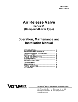
WORM GEAR ACTUATOR MAINTENANCE: A
typical worm gear actuator is shown in Figure 10 and
consists of a worm (3) mounted on an input shaft (9).
The worm engages a segment gear (2). When the
worm is turned, it drives the segment gear through
90° of rotation. The rotation of the segment gear is
displayed by the top indicator (5). The gears are
lubricated with EP2 grease in a cast iron housing (1).
The open and closed positions of the segment gear
(2) are controlled by the end position stop bolts (20).
The stops can be adjusted by loosening the lock nut
(21) and rotating the bolts (20).
The gear box is factory lubricated and sealed. No
regular maintenance is required. If difficult operation
is observed, the cover can be removed and the unit
inspected for wear. All moving parts should be coated
with grease. The grease should have an even and
smooth consistency. If needed, coat all moving parts
with an EP-2 grease such as Mobil Mobilux EP2.
Buried units should be packed 100% with grease.
FIGURE 10. GEAR ACTUATOR CONSTRUCTION
Table 6. Worm Gear Parts List
Item Description Material
1Housin
g
Cast Iron
2Se
g
ment Gear Ductile Iron
3Worm
A
llo
y
Steel
4 Cover Cast Iron
5 Indicator Cast Iron
6O-Rin
g
Buna-N
7 Thrust Bearin
g
Carbon Steel
8 Bearin
g
Bronze
9 Shaft Carbon Steel
10 Gaske
t
Non-
A
sbestos
11 Handwheel Cast Iron
12 Operatin
g
Nut Cast Iron
13 Chainwheel Steel
14 Cover Bol
t
Carbon Steel
15 Indicator Bolt Steel
18 Worm Pin Steel
19 Handwheel Pin Steel
20 Stop Screw Steel
21 Jam Nu
t
Steel
23 Oil Seal Steel & Rubber
Grease EP-2

9
MAINTENANCE (Cont'd)
TRAVELING NUT ACTUATOR MAINTENANCE: A
typical traveling nut actuator is shown in Figure 11
and consists of a threaded nut (12) which travels back
and forth on a threaded stem (14). The stem is
lubricated with EP2 grease in a cast iron housing (1).
The nut, in turn, drives a slotted lever (4) through 90
degrees of travel. The lever (4) drives the valve shaft
with a square key. The rotation of the shaft is
displayed by the top indicator (19). The full open and
closed positions are controlled by the stop nuts (6).
The stop nuts can be adjusted by pounding out the
pin (7) with a drift punch and rotating the stop nut ½
turn. The gear box is factory lubricated and sealed.
No regular maintenance is required. If difficult
operation is observed, the cover can be removed and
the unit inspected for wear. All moving parts should
be coated with grease. The grease should have an
even and smooth consistency. If needed, coat all
moving parts with an EP-2 grease such as Mobil
Mobilux EP2. Buried units should be packed 100%
with grease.
FIGURE 11. TRAVELING NUT ACTUATOR
Table 7. Travelin
g
Nut Actuator Parts
Item Description Material
1Housin
g
Cast Iron
2Housin
g
Cover Cast Iron
3 Cover Bol
t
Steel
4 Lever Ductile Iron
5Plu
g
Steel
6 Stop Nu
t
Steel
7 Stop Nut Pin Steel
8 End Cap Cast Iron
9 End Cap O-Rin
g
Buna-N
10 Stem Collar Bronze
11 Collar Pin Steel
12 Crosshead Bronze
13 Shaft O-Rin
g
Buna-N
14 Stem
A
llo
y
Steel
15 End Cap Bolts Steel
16 Handwheel Steel
17 Pin Steel
18 Indicator Bolt Steel
19 Indicator
A
luminum
20 Needle Bearin
g
s Steel
21 Bearin
g
Race Steel
22 Shaft Bearin
g
Teflon/Fiber
g
lass
30 Gaske
t
Composition Rubber
31 Indicator Extension Steel
32 Extension Pin Steel
33 Operatin
g
Nut Cast Iron
34 Chainwheel Kit Ductile Iron
Grease EP-2

10
TROUBLESHOOTING
Several problems and solutions are presented below
to assist you in troubleshooting the valve assembly in
an efficient manner.
Leakage at Valve Shaft: Replace packing.
Leakage at Flanges: Tighten flange bolts, replace
gasket.
Valve Leaks when Closed: Flush debris from seat by
cycling valve. Adjust actuator closed stop. Inspect
seat for damage and adjust seat bolts 1/4 turn at a
time.
If the valve continues to leak after adjustment, check
for the following items and make the corrections.
1. Verify that there is no damage to the rubber seat.
Replace if torn or damaged.
2. Check that the metal set in the body is clean and
free of scale and scratches.
3. Check that the actuator is fully closed and the seal
is centered in the body seat. Adjustment to the
actuator stop nuts or bolts may be necessary.
4. Check the roundness of the adjoining pipe and
pipe flange. Pipe loads may cause distortion to the
adjoining pipe and valve.
5. Verify that the test pressure is less than the cold
working pressure (CWP) shown on the valve
nameplate.
Hard to Open: Flush line of debris. Check grease in
actuator. Check interior of valve for deposits or
debris. On buried valves, check alignment of
operating stem and nut.
Leaking Oil: Tighten actuator cover bolts. If leak
persists, remove actuator cover, inspect grease,
and replace actuator gasket.
Noisy Operation: Flow noise is normal. Loud flow
noise similar to hammering may be cavitation from
dropping high pressures across valve; review
application of valve. For gear actuator noise,
inspect grease; add new grease if there are
uncoated moving parts or grease has broken down
into oil.
DISASSEMBLY
Disassembly may be required to repair the valve.
Work on the valve should be performed by a skilled
mechanic with proper tools and a power hoist for large
valves. The valve must be removed from the pipeline
for disassembly. The actuator can be removed with
the valve in the line (the line must be drained) or after
the valve is removed from the line. Refer to Figure 2
for valve construction and parts.
1. Open valve slightly and drain the pipeline. Close
valve until disc edge just touches the seat. Valve
and actuator can be removed as a unit from the
pipeline.
2. Remove the small cover on the actuator to expose
the shaft key. Remove the actuator mounting bolts
and lift actuator from valve taking care not to lose
key (14). Access to the traveling nut actuator will
be under the actuator cover.
3. Remove bottom cap screws (16) and thrust
bearing cap (15). Remove the seat bolts (8) and
seat retaining ring (7).
4. Matchmark the taper pins with the disc holes.
Remove the taper pin nuts (11) and taper pins (9).
Press or hammer out the shaft (4) with a dead blow
hammer. The bearings (5) will likely be pushed out
with the shaft.
5. Clean and inspect parts. Replace worn parts as
necessary and lubricate parts with FDA grease.
WARNING
Open valve and drain line before removing
actuator or the valve may suddenly open
causing injury or fluid loss. Place valve in
closed or slightly open position to remove
from the line or damage to the disc edge may
occur.

11
REASSEMBLY
All parts must be cleaned and gasket surfaces should
be cleaned with a stiff wire brush in the direction of
the serrations or machine marks. Worn parts, gaskets
and seals should be replaced during reassembly.
Bolts should be lubricated and torqued per Table 8
during reassembly
Table 8. Lubricated Bolt Torques
Size Torque
(
ft-lbs
)
3/8”-16 20-30
7/16”-14 30-50
1/2”-13 45-75
5/8”-11 100-150
3/4”-10 150-250
7/8”-9 200-350
1”-8 300-500
1 1/8”-7 450-700
1 1/4”-7 650-1000
1. Insert new bearings (5) into both ends of the valve
body (1) and insert the shaft (4) through the body
and disc (3).
2. Install taper pins (9) with washers (12) and nuts
(11).
3. Install new seat (6), retaining ring (7) and seat
bolts (8) into disc. Apply thin film of FDA silicone
grease such as Dow Corning #7 to rubber
surface. Lightly tighten seat bolts until bolt heads
touch ring.
4. Lubricate ID and OD of packing set with FDA
grease and install in packing bore one ring at a
time taking care to keep lips pointing down toward
valve.
5. Center disc in body and install bottom thrust
bearing (18) and cap (15). Secure with cap
screws (16).
6. Torque cap screw to torque given in Table 8.
7. Insert key (14) into shaft and place actuator over
valve. Reinstall actuator mounting bolts and
torque per Table 8. Install cover on actuator.
Cycle valve. Apply pressure to valve and check
for seat leakage. Tighten seat bolts ½ turn at a
time as necessary.
8. If valve does not shut off tight, adjust the closed
position stops as described on page 6 under
"Closed Position Adjustment".
SEAT REPLACEMENT
If the seat is badly worn or damaged, gain access to
valve interior and remove existing cap screws, seat
retaining ring, and seat.
1. Clean mating surfaces of body seat, disc, and
retaining ring with stiff wire brush in the direction
of the machine grooves.
2. Install new seat (6) onto disc so that the o-ring
bead side is against the disc with the holes
aligned.
3. Start at the top of the disc and install a section of
retaining ring (7) with three new seat hex head
cap screws (8) and lightly tighten seat bolts until
the bolt heads touch the retaining ring.
4. Apply a thin film of FDA silicone grease such as
Dow Corning #7 to the exposed rubber surface
and close the valve so that the disc is level with
the flange face within +/- 1/8 in.
5. Tighten the seat hex head cap screw in a cross-
over pattern in two steps to the torque given in
Table 5 using a socket wrench. Do not attempt to
re-tighten seat hex head cap screws to their initial
torques at a later time.
6. Cycle valve open and closed and verify that disc
closes within +/- 1/8 in of center. Conduct a
pressure test. If necessary, tighten seat hex head
cap screw ½ turn to stop any leakage.
FIGURE 12. SEAT REPLACEMENT

12
PARTS AND SERVICE
Parts and service are available from your local
representative or the factory. Make note of the valve
Size, Series No, and Serial No. located on the valve
nameplate and contact:
Val-Matic Valve and Mfg. Corp.
905 Riverside Drive
Elmhurst, IL 60126
Phone: (630) 941-7600
Fax: (630) 941-8042
www.valmatic.com
A sales representative will quote prices for parts or
arrange for service as needed
.
VAL-MATIC
®
VALVE AND MANUFACTURING CORP.
905 Riverside Dr. ● Elmhurst, IL 60126
Phone (630) 941-7600 ● Fax (630) 941-8042
www.valmatic.com
LIMITED WARRANTY
All products are warranted to be free of defects in material and workmanship for a period of one year from the
date of shipment, subject to the limitations below.
If the purchaser believes a product is defective, the purchaser shall: (a) Notify the manufacturer, state the alleged
defect and request permission to return the product; (b) if permission is given, return the product with
transportation prepaid. If the product is accepted for return and found to be defective, the manufacturer will, at
his discretion, either repair or replace the product, f.o.b. factory, within 60 days of receipt, or refund the purchase
price. Other than to repair, replace or refund as described above, purchaser agrees that manufacturer shall not
be liable for any loss, costs, expenses or damages of any kind arising out of the product, its use, installation or
replacement, labeling, instructions, information or technical data of any kind, description of product use, sample
or model, warnings or lack of any of the foregoing. NO OTHER WARRANTIES, WRITTEN OR ORAL, EXPRESS
OR IMPLIED, INCLUDING THE WARRANTIES OF FITNESS FOR A PARTICULAR PURPOSE AND
MERCHANTABILITY, ARE MADE OR AUTHORIZED. NO AFFIRMATION OF FACT, PROMISE,
DESCRIPTION OF PRODUCT OF USE OR SAMPLE OR MODEL SHALL CREATE ANY WARRANTY FROM
MANUFACTURER, UNLESS SIGNED BY THE PRESIDENT OF THE MANUFACTURER. These products are
not manufactured, sold or intended for personal, family or household purposes.
/